Table of Contents
Advertisement
Quick Links
Download this manual
See also:
User Manual
Advertisement
Table of Contents

Related Manuals for Conel UR5


Summary of Contents for Conel UR5
-
Page 2: Table Of Contents
2.5. Antenna Connection 2.6. SIM Card Reader 2.7. Power Supply 2.8. Technical parameters 2.9. Description of the individual components of the UR5 2.9.1. UMTS module 2.9.2. Control microcomputer 2.10. User interfaces (Connectors) 2.10.1. Connection of the PWR Supply Connector 2.10.2. - Page 3 Attention – notice on possible problems, which can arise to in specific cases. Information, notice – information, which contains useful advices or special interest. Conel s.r.o., Sokolska 71, 562 04 Usti nad Orlici, Czech Republic Issue in CZ, 12/13/2007 - 3 -...
-
Page 4: Safety Instruction
Unauthorized modifications or utilization of accessories that have not been approved may result in the termination of the validity of the guarantee. • The communication module UR5 must not be opened. Only the replacement of the SIM card is permitted. •... -
Page 5: Description Of The Ur5 Router
HSDPA/UMTS/EDGE/GPRS PPP connection. By means of the integration of a DHCP server it provides the user with simple installation and Internet access. In addition, the UR5 router is equipped with a USB 2.0 Host interface which is designed only for connection to a USB device. -
Page 6: Hsdpa Technology (High Speed Download Packet Access)
DESCRIPTION OF THE UR5 ROUTER 2.3. HSDPA technology (High Speed Download Packet Access) HSDPA is an improved and extended version of the UMTS-TDD. HSDPA is available for both UMTS FDD and for UMTS TDD. HSDPA raises essential bit rate for downlink. It is attained on the programmer level. -
Page 7: Antenna Connection
• for mounting onto a DIN rail, the plastic clips are included 2.5. Antenna Connection The external antenna is connected to the UR5 using an the FME connector on the back panel. External antenna:... -
Page 8: Sim Card Reader
PIN in the reader. 2.7. Power Supply The UR5 requires +10 V DC to +30 V DC supply. Protection against reversed polarity without signaling is built into the modem. The power consumption during receiving is 1W. The peak power consumption during data sending is 3.5W. -
Page 9: Technical Parameters
DESCRIPTION OF THE UR5 ROUTER 2.8. Technical parameters HSDPA/UMTS/EDGE/GPRS module SIEMENS HC15 Complies with standards 3GPP TS 51.010–1, 3GPP TS 34.121, 3GPP TS 34.123–1, 3GPP TS 34.123–3, ETSI EN 301 511 V9.0.2, ETSI EN 301 489–1 V1.4.1, ETSI EN 301 489–7 V1.2.1, EN 60950–1 ed.2:2006,... -
Page 10: Description Of The Individual Components Of The Ur5
For interconnecting devices the modem provides the DHCP service (Dynamic Host Configuration Protocol) which enables individual clients (computers) to achieve the TCP/IP configuration when being put into operation. The IP address is set with the assistance of UR5. Thanks to the NAT function (Network Address Translation) the modem enables the sharing of the Internet connection by many computers. -
Page 11: User Interfaces (Connectors)
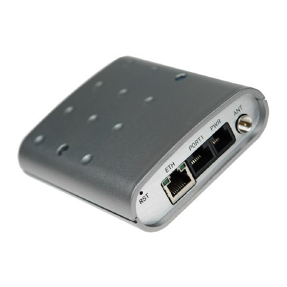
DESCRIPTION OF THE UR5 ROUTER 2.10. User interfaces (Connectors) On the back panel of UR5 the following connectors are located: • one RJ12 connector (PWR) – for connection of the power supply adapter, • one RJ45 connector (ETH) – for connection into the local equipment, •... -
Page 12: Connection Of The Pwr Supply Connector
DESCRIPTION OF THE UR5 ROUTER 2.10.1. Connection of the PWR Supply Connector Panel socket RJ12. Signal Description number mark Positive pole of DC supply voltage (10 to 30 V) Signal not connected Signal not connected Positive pole of DC supply voltage (10 to 30 V) -
Page 13: Connection Of The Port1 Connector - Rs485
DESCRIPTION OF THE UR5 ROUTER The UR 5 connection to the PC: Cable KD-2 Router UR 5 PORT1 • cable KD2 is connected to serial port PC (example COM1) The UR 5 connection to equipment with full-value RS232 interface: Cable KD-2... -
Page 14: Connection Of The Port1 Connector - Mbus
DESCRIPTION OF THE UR5 ROUTER Circuit example: Pin 1 – SGND Pin 2 – SGND Pin 3 – RS485 (-) Meter Pin 4 – RS485 (+) Router UR 5 Pin 5 – RS485 (-) Pin 6 – RS485 (+) Pin 7 – +12V EXT Pin 8 –... -
Page 15: Connection Of The Eth Connector
DESCRIPTION OF THE UR5 ROUTER 2.10.5. Connection of the ETH Connector Panel socket RJ45. Signal Description Data flow direction number mark TXD+ Transmit Data – positive pole Input/Output TXD- Transmit Data – negative pole Input/Output RXD+ Receive Data – positive pole... -
Page 16: Technical Specification Of Optional Port1
DESCRIPTION OF THE UR5 ROUTER 2.11. Technical specification of optional PORT1 • Expansion port RS232 Name of product Expansion port RS232 Power supply Internal ..Environment Operating temperature -20 .. +55 C Storage temperature -20 .. +85 C Standards Emission... -
Page 17: Modem Status Indication
Color Description Description Blinking 1:9 ....join connection Front Green Blinking 9:1 ....establishing of connection Permanently on ……….. starting of the UR5 Front Blinking ……….. communication in progress On ...... selected 100 Mbit/s Back Green – Off ...... selected 10 Mbit/s On...... -
Page 18: Putting Into Operation
DESCRIPTION OF THE UR5 ROUTER 2.13. Putting into operation Before putting the UR5 router into operation it is necessary to connect all components needed for the operation of your applications and the SIM card must be inserted (the modem is off). - Page 19 DESCRIPTION OF THE UR5 ROUTER For compliance of EN 60439 - 1 + A1 specification it is necessary observe next assembly of the modem to the switch - board: • round antenna we recommend to observe a distance of 6 cm from cables and metal...
- Page 20 DESCRIPTION OF THE UR5 ROUTER • sufficient space must be left before individual connectors for handling of cables, • for correct function of the modem we recommend to use in switch - board earth- bonding distribution frame for grounding of power supply of modem, data cables and antenna, •...
-
Page 21: Expansion Port Mounting
EXPANSION PORT MOUNTING 3. Expansion port mounting Attention! Expansion port PORT1 include when the router UR 5 is switch off. After unscrewed two screws (position 8) on box bottom part (position 3) and carried out box top part (position 2) the expansion port PORT1 (position 6) connect to connector J3 (see below) of the router B-UR-5 motherboard (position 1) from TOP side. - Page 22 EXPANSION PORT MOUNTING Parts list and description Part Description Number UMTS router UR 5 motherboard UR 5 box top part UR 5 box bottom part UR 5 rear head UR 5 front head Expansion port Distant columns for expansion port PORT1 mounting to motherboard Screw for box completion...
-
Page 23: Change Of The Sim Cards
CHANGE OF THE SIM CARDS 4. Change of the SIM cards Attention! SIM card include when the router UR 5 is switch off. First SIM card change: Ensure that the modem is disconnected from the power supply. Press the small yellow button next to the reader to eject the reader holder. - Page 24 CHANGE OF THE SIM CARDS The second SIM socket mounting...
- Page 25 CHANGE OF THE SIM CARDS Parts list and description Part Description Number UMTS router UR 5 motherboard UR 5 box top part UR 5 box bottom part UR 5 rear head UR 5 front head Screw for box completion Adapter for the second SIM card...
-
Page 26: Configuration Setting Over Web Browser
CONFIGURATION 5. Configuration setting over web browser Attention! If the SIM card isn’t included in the UR5 router, it is impossible for the UR5 router to operate. The Included SIM card must be activated for HSDPA/UMTS/EDGE/GPRS UMTS transmissions. Insert the SIM card when the UR5 router is switched off. - Page 27 CONFIGURATION • RX packets – received packets, errors – number of errors, dropped – dropped packets • TX packets – transmit packets, errors – number of errors, dropped – dropped packets • collisions – number of collisions • RX bytes – total number of received bytes, TX bytes – total number of transmit bytes •...
-
Page 28: Dhcp Status
CONFIGURATION 5.2. DHCP Status Information about the IP address which was allotted by DHCP server to UR5; it is possible to find in menu in sum DHCP: • lease 192.168.1.2 (generally IP address) – assigned IP address • starts – information about time of assigned IP address •... -
Page 29: Dyndns Status
CONFIGURATION 5.5. DynDNS status DynDNS up - data entry result on server www.dyndns.org can be called - up in option DynDNS item in the menu. 5.6. System Log In case of any problems with PPP connection it is possible to view the system log by pressing the System Log menu item. -
Page 30: Umts/Gprs Configuration
CONFIGURATION In the second part of window, it is possible to define the DHCP server by checking the Enable DHCP server option. In the window it is possible to define the beginning (IP Pool Start) and end (IP Pool End) of the pool of IP addresses that will be assigned to DHCP clients. The changes in settings will apply after pressing the Apply button. -
Page 31: Firewall Configuration
CONFIGURATION Attention! Check PPP connection we recommended in case of uninterrupted running. Note: • MTU (Maximum Transmission Unit) – it identifies the maximal size of packet that it is possible to transfer in the given environment. • MRU (Maximum Receiving Unit) – it identifies the maximal size of packet that it is possible to receive in the given environment. - Page 32 CONFIGURATION of the Default Server item it is possible to put the UR5 router into the mode in which all incoming data from UMTS will be routed to the computer with the defined IP address. If the Enable remote HTTP access and port number field is filled in, it is possible to configure the router over the web interface.
- Page 33 In this configuration the address defines Server IP Address equipment wired behind the UR5. For PING on IP address of the SIM card matches UR5. Access to the web interface of equipment behind UR5 is possible by the help of Port Forwarding, when after the IP address of SIM is given the external port of the equipment on which we want to join.
-
Page 34: Gre Tunnel Configuration
CONFIGURATION 5.11. GRE Tunnel Configuration To enter the GRE tunnel configuration, select the GRE menu item. In the window it is possible to define the IP address of the remote side of the tunnel (Remote External IP Address), internal IP address of the local side of the tunnel (Local Internal IP Address), internal IP address of the remote side of the tunnel (Remote Internal IP Address), address of the network behind the remote side of the tunnel (Remote Subnet) and the mask of the network behind the remote side of the tunnel (Remote Subnet Mask). -
Page 35: L2Tp Configuration
To enter the L2TP tunnel configuration, select the L2TP menu item. In the window it is possible to define L2TP tunnel mode (Mode) on UR5 side, in case of client IP address of server (Server IP Address), start IP address in range, which is offered by server to clients... -
Page 36: Dyndns Client Configuration
CONFIGURATION Configuration of the L2TP tunnel: Mode L2TP Server L2TP Client Server IP Address 10.0.0.1 Client Start IP Address: 192.168.3.2 Client End IP Address: 192.168.3.254 Local IP Address: 192.168.3.1 Remote IP Address Remote Subnet 192.168.2.0 192.168.1.0 Remote Subnet Mask 255.255.255.0 255.255.255.0 Username uživatel... -
Page 37: External Port Configuration
CONFIGURATION possible to send to two telephone numbers. Unit ID is the name of the UR5 that it will send a SMS message to. Unit ID may have a random form. By the choice Enable AT-SMS protocol on external port is possible send/receive a SMS on serial port. - Page 38 CONFIGURATION Example of external port configuration: ppp0 10.0.0.2 ppp0 10.0.0.1 RS232 192.168.1.1 192.168.1.100 Settings in application on PC: Settings in UR-5 TCP connection on 10.0.0.2:2000 Mode: TCP server Server Address: - Default Gateway 192.168.1.1 TCP Port: 2000 ppp0 10.0.0.2 RS232 ppp0 10.0.0.1 RS232 Settings in UR-5...
-
Page 39: Usb Port Configuration
CONFIGURATION 5.17. USB Port Configuration The USB port configuration can be selected by option USB Port in menu. Inside the window can be defined baudrate, number of data bits, parity, number of stop bits and mode. Split timeout is for messages. In mode TCP server it is necessary to enter the TCP port, on which the router will listen to incoming requests about TCP connection. -
Page 40: Change Password
Password menu item. The new password will be saved after pressing the Apply button. In the basic setting of the UR5 router, the password is set on default form root. For higher security of our network we recommend to change this password. -
Page 41: Update Firmware
We strongly recommend not to remotely update due to PPP connection, it could damage the router. 5.24. Reboot To reboot the UR5 router select the Reboot menu item and then press the Reboot button. -
Page 42: Default Settings
CONFIGURATION 5.25. Default settings LAN Configuration 5.25.1. UMTS/GPRS Configuration 5.25.2. Firewall Configuration 5.25.3. -
Page 43: Nat Configuration
CONFIGURATION NAT Configuration 5.25.4. IPsec Tunnel Configuration 5.25.5. GRE Tunnel Configuration 5.25.6. -
Page 44: L2Tp Tunnel Configuration
CONFIGURATION L2TP Tunnel Configuration 5.25.7. DynDNS Configuration 5.25.8. NTP Configuration 5.25.9. SMS Configuration 5.25.10. -
Page 45: External Port Configuration
CONFIGURATION External Port Configuration 5.25.11. USB Port Configuration 5.25.12. -
Page 46: Configuration Setting Over Telnet
CONFIGURATION 6. Configuration setting over Telnet Attention! If the SIM card isn’t included in the UR 5 router, it is impossible for the UR 5 router to operate. The Included SIM card must be activated for HSDPA/UMTS/EDGE/GPRS transmissions. Insert the SIM card when the UR 5 router is switched off. Monitoring of status, configuration and administration of the UR 5 router can be performed by means of the Telnet interface. - Page 47 CONFIGURATION tcpdump monitoring of network touch file create text editor...
-
Page 48: Possible Problems
NAT or firewall. NAT is possible to verify by the help of ping to a random address of your server with a fixed IP address and by the help of the UR5 control address and address in ping. -
Page 49: Customers Support
RS232 don’t function. It is necessary to verify the presence of the RS232 expansion port. Verify the presence of the RS232 expansion port in the UR5 configuration in menu „external port“, or verify connection locally by the help Telnet-Hyper terminal. -
Page 50: Guarantee Claim Guidelines
GUARANTEE 11. Guarantee Claim Guidelines Dear customer, The product that you have purchased was tested by the manufacturer and, before it was sold, the product’s functions were checked once more by our company’s technician. However if, in spite of the above-mentioned measures, a breakdown of this product occurs during the guarantee period, which makes proper utilization of the product impossible, we ask you to observe the Guarantee Claim Guidelines when asserting a guarantee claim. - Page 51 GUARANTEE the exchange of the IMEI), the ownership of the original object of the guarantee claim is passed hereupon onto the seller, and the ownership of the new product, onto the buyer. A new guarantee period starts running from the date of acceptance of the new product. In the event that the seller, upon agreement with the customer, has settled the guarantee claim by exchanging the object of the guarantee claim for a faultless product, the new guarantee of the product shall expire as follows:...
- Page 52 GUARANTEE For the assessment whether a defect has occurred, the product parameters included in the technical documentation of the product are decisive. The guarantee shall be terminated in the event of any modification of the object of the guarantee claim or in the event that the serial number of the object of the guarantee claim has been damaged or is illegible due to other reasons.
-
Page 53: Guarantee Certificate
GUARANTEE CERTIFICATE 12. Guarantee certificate Type of the device Serial number Guarantee period (in months) Seller Date of sale Stamp of the seller... - Page 54 GUARANTEE CERTIFICATE Date of reception of the guarantee claim by the seller Number of the guarantee claim report Date of reception of the device into the repair shop Date of completion of the repair by the repair shop Number of the receipt form of the repair shop Guarantee repair...
Need help?
Do you have a question about the UR5 and is the answer not in the manual?
Questions and answers