
Related Manuals for Conel xr5i


Summary of Contents for Conel xr5i
- Page 1 WWW.INFOPULSAS.LT info@infopulsas.lt XR5i XR5i SL Router USER’S GUIDE Declared system ISO 9001:2009...
-
Page 2: Table Of Contents
Modem status indication 2.10. Putting into operation 2.11. Mechanical external dimensions and mounting recommendations Expansion port mounting 3.1. Expansion port mounting for XR5i 3.2. Expansion port mounting for XR5i SL Configuration setting over web browser 4.1. Network Status 4.2. DHCP Status 4.3. - Page 3 CONTENTS 4.24. Change profile 4.25. Change password 4.26. Set real time clock 4.27. Backup Configuration 4.28. Restore Configuration 4.29. Update firmware 4.30. Reboot 4.31. Default settings 4.31.1. LAN Configuration 4.31.2. VRRP Configuration 4.31.3. Firewall Configuration 4.31.4. NAT Configuration 4.31.5. OpenVPN Tunnel Configuration 4.31.6.
- Page 4 Information, notice – information, which contains useful advices or special interest. GPL licence Source codes under GPL licence are available free of charge by sending email on info@conel.cz. Conel s.r.o., Sokolska 71, 562 04 Usti nad Orlici, Czech Republic Issued in CZ, 5/11/2011 - 4 - 11.5.2011...
-
Page 5: Safety Instruction
SAFETY INSTRUCTION 1. Safety instruction Please, observe the following instructions: • The communication router must be used in compliance with all applicable international and national laws and in compliance with any special restrictions regulating the utilization of the communication router in prescribed applications and environments. •... -
Page 6: Description Of The Router
USB 1.1 Host interfaces which is designed only for connection to a USB device. The ethernet router has two versions. The first version is basic XR5i and the second version is XR5i SL in the aluminum box. -
Page 7: Power Supply
DESCRIPTION Example of expansion port XPORT: Trade name Type name Power supply Expansion port ETH XC-ETH Internal power supply Basic delivered set of router includes: • ethernet router, • power supply, • crossover UTP cable, • plastic clips for the DIN rail with fixing screws, •... -
Page 8: Technical Parameters
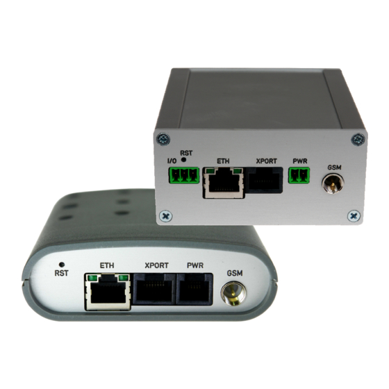
RJ45 connector (optional XPORT) – for connection of the local any arrangement, • one MRT9 (I/O) – interface with one binary input and with one binary output (only version XR5i SL) • two USB-A Host connectors (USB) – for connection of the devices to the router, USB’s... - Page 9 DESCRIPTION Front panel XR5i Rear panel XR5i Front panel XR5i SL Rear panel XR5i SL...
-
Page 10: Connection Of The Pwr Supply Connector
DESCRIPTION 2.6.1. Connection of the PWR Supply Connector Panel socket RJ12. Signal Description number mark Positive pole of DC supply voltage (+10 to +30 V) Signal not connected Signal not connected Positive pole of DC supply voltage (+10 to +30 V) Negative pole of DC supply voltage Negative pole of DC supply voltage Circuit example:... -
Page 11: Connection Of The Xport Connector - Eth
DESCRIPTION 2.6.2. Connection of the XPORT Connector – ETH Panel socket RJ45. Signal mark Description Data flow direction number TXD+ Transmit Data – positive pole Input/Output TXD- Transmit Data – negative pole Input/Output RXD+ Receive Data – positive pole Input/Output RXD- Receive Data –... -
Page 12: Connection Of The I/O Connector
Example of the I/O router connection: +12 V Pin 1 - BIN Router Pin 2 - GND Pin 3 - OUT I/O port is part of the XR5i SL version only. 2.6.5. Connection of the Connector USB Panel socket USB-A. Signal mark Description... -
Page 13: Technical Specification Of I/O Port
Binary input reed contact with trigger level 1,3 up to 1,4 V Binary output 120 mA/max. 30 V I/O port is part of the XR5i SL version only. 2.8. Technical specification of expansion ETH XPORT Expansion port ETH Power supply Internal .. -
Page 14: Modem Status Indication
Off ....... the network cable is not connected 2.10. Putting into operation Before putting the XR5i or XR5i SL router into operation it is necessary to connect all components needed for the operation of your applications. The router is put into operation by connection of the power supply to the router. -
Page 15: Mechanical External Dimensions And Mounting Recommendations
DESCRIPTION 2.11. Mechanical external dimensions and mounting recommendations... - Page 16 DESCRIPTION For the majority of applications with a built-in router in a switch board it is possible to recognize two sorts of environments: • no public and industry environment of low voltage with high interference, • public environment of low voltage without high interference. For both of these environments it is possible to mount routers to switch board, the following it is not need have no examination immunity or issues in connection with EMC according to EN 60439-1 ed.2:00 + A1:04.
- Page 17 DESCRIPTION • the circuit diagram of the XR5i router is on the following pictures, • the circuit diagram of the XR5i SL router is on the following pictures.
-
Page 18: Expansion Port Mounting
3. Expansion port mounting 3.1. Expansion port mounting for XR5i Attention! Expansion port XPORT include when the router XR5i is switch off. After unscrewed two screws (position 8) on box bottom part (position 3) and carried out box top part (position 2) the expansion port XPORT (position 6) connect to connector J3 (see below) of the router B-UR-5i motherboard (position 1) from TOP side. - Page 19 EXPANSION PORT MOUNTING Parts list and description Part Description Number Router motherboard Box top part Box bottom part Rear head Front head Expansion port Distant columns for expansion port XPORT mounting to motherboard Screw for box completion...
-
Page 20: Expansion Port Mounting For Xr5I Sl
EXPANSION PORT MOUNTING 3.2. Expansion port mounting for XR5i SL Attention! Expansion port XPORT include when the router XR5i SL is switch off. After unscrewing four screws (position 10) on the rear panel (position 5) and removing it is possible to take out the B-UR-5i motherboard (position 1). The expansion port XPORT (position 2) is connected to connector J3 (see below) of the router B-UR-5 motherboard (position 1) from TOP side. - Page 21 EXPANSION PORT MOUNTING Parts list and description Part Description Number UMTS router motherboard Expansion port XPORT Left box part Right box part Rear head Front head Bottom box part Top box part Spacers for expansion port XPORT mounting to motherboard Screw for box completion...
-
Page 22: Configuration Setting Over Web Browser
CONFIGURATION 4. Configuration setting over web browser Monitoring of the status, configuration and administration of the router can be performed by the web interface, which is available after insertion of IP address of the router into the web browser. The default IP address of the router is 192.168.1.1. Configuration may be performed only by the user "root"... -
Page 23: Network Status
CONFIGURATION 4.1. Network Status view system information about router operation, select the System Information menu item. The bottom part of the window contains information about the system memory usage. The upper part of the window displays detailed information about active interfaces: •... -
Page 24: Dhcp Status
CONFIGURATION 4.2. DHCP Status Information about IP addresses, which was leased to the router by the DHCP server, is possible to find in menu in sum DHCP: • lease 192.168.1.2 (generally IP address) – assigned IP address • starts – information about time of assignation of IP address •... -
Page 25: System Log
CONFIGURATION 4.5. System Log In case of any problems with connection it is possible to view the system log by pressing the System Log menu item. The System log observes only connection and formation of IPsec tunnel. The upper part of the window displays possible errors at connection establishment. - Page 26 CONFIGURATION The DHCP server can be used for Primary LAN (port ETH) only. In case of use the DHCP server on the Primary LAN is impossible to use the DHCP client on the same port and in case of use the DHCP client is impossible to use the DHCP server. In the fourth part of the Windows it is possible, by checking the Enable static DHCP server option, to define leases up to six static IP Addresses, which conform to MAC Address of the connected equipment etc.
- Page 27 CONFIGURATION Example of the network interface with dynamic DHCP server: 192.168.1.2 192.168.1.1 192.168.1.3 192.168.1.4...
- Page 28 CONFIGURATION Example of the network interface with dynamic and static DHCP server: 192.168.1.2 192.168.1.3 192.168.1.4 192.168.1.1 192.168.1.10 01:23:45:67:89:ab 192.168.1.11 01:54:68:18:ba:7e...
- Page 29 CONFIGURATION Example of the network interface with dynamic DHCP server and DHCP client: 192.168.1.2 192.168.1.3 ETH port 192.168.1.254 192.168.1.1 XPORT ETH DHCP server...
- Page 30 CONFIGURATION Example of the network interface with default gateway and DNS server: 192.168.1.2 192.168.1.3 192.168.1.4 192.168.1.1 192.168.1.20...
-
Page 31: Vrrp Configuration
CONFIGURATION 4.7. VRRP Configuration To enter the VRRP configuration select the VRRP menu item. VRRP protocol (Virtual Router Redundancy Protocol) is a technique, by which it is possible to forward routing from main router to backup router in the case of the main router failure. If the Enable VRRP is checked, then it is possible to set the following parameters. -
Page 32: Pppoe Configuration
CONFIGURATION Example of the VRRP protocol: Main router Virtual server ID 5 Host priority 255 APN 1 192.168.1.2 192.168.1.1 10.0.1.3 APN 2 Backup router 192.168.1.3 Virtual server ID 5 Host priority 100 4.8. PPPoE Configuration To enter the PPPoE configuration select the PPPoE menu item. If the Create PPPoE connection option is selected, the router tries to establish PPPoE connection after switching- on. -
Page 33: Firewall Configuration
CONFIGURATION 4.9. Firewall Configuration By the help of a firewall it is possible to set IP addresses from which are possible to remotely access the router. The choice Allow remote access only from specified hosts is given for easier configuration of hosts. In this firewall configuration it is possible to set up to four remote accesses by the help of Source, Source IP Address, Protocol and Target Port. -
Page 34: Nat Configuration
CONFIGURATION Example of the firewall configuration: TCP/1000 10.0.2.123 ICMP 171.92.5.45 142.2.26.54 4.10. NAT Configuration To enter the Network Address Translation configuration, select the NAT menu item. By checking Send all incoming packets to default server item setting the Default Server item it is possible to put the router into the mode in which all incoming data from WAN will be routed to the computer with the defined IP address. - Page 35 CONFIGURATION Choice Masquerade outgoing packets option turns the system address translation NAT. The changes in settings will apply after pressing the Apply button.
- Page 36 CONFIGURATION Example of the configuration with one connection equipment on the router: 162.209.13.222 ppp0 10.0.0.1 192.168.1.2 In these configurations it is important to have marked choice of Send all remaining incoming packets it default server, IP address in this case is the address of the device behind the router.
- Page 37 CONFIGURATION Example of the configuration with more connected equipment: SWITCH 162.209.13.222 10.0.0.1:81 ppp0 10.0.0.1 10.0.0.1:82 192.168.1.2:80 10.0.0.1:83 192.168.1.3:80 192.168.1.4:80...
-
Page 38: Openvpn Tunnel Configuration
CONFIGURATION In this configuration equipment wired behind the router defines the address Server IP Address. The router replies, while PING on its address. Access on web interface of the equipment behind the router is possible by the help of Port Forwarding, when behind IP address of indicating public port of equipment on which we want to come up. - Page 39 CONFIGURATION By parameter NAT Rules it is possible to apply set NAT rules to OpenVPN tunnel. By Authenticate Mode it is possible to choose authentication. On choice are none authentication, or by Pre-shared secret which set shared key for both off-side tunnel; or by Username/Password which enable authentication by CA Certificate, Username and Password;...
- Page 40 CONFIGURATION...
- Page 41 CONFIGURATION Example of the OpenVPN tunnel configuration: 192.168.1.2 192.168.2.2 ppp0 10.0.0.2 192.168.2.0 tun 0 19.16.2.0 ppp0 10.0.0.1 192.168.1.0 tun0 19.16.1.0 192.168.1.3 OpenVPN tunnel 192.168.2.3 192.168.1.4 192.168.2.4 Default Gateway 192.168.2.1 Default Gateway 192.168.1.1 OpenVPN tunnel configuration: Protocol UDP Port 1194 1194 Remote IP Address: 10.0.0.2 10.0.0.1...
-
Page 42: Ipsec Tunnel Configuration
CONFIGURATION 4.12. IPSec Tunnel Configuration IPsec tunnel configuration can be called up by option IPsec item in the menu. IPsec tunnel allows protected connection of two networks LAN to the one which looks like one homogenous. In the IPsec Tunnels Configuration window are four rows, each row for one configured IPSec tunnel. - Page 43 CONFIGURATION...
-
Page 44: Gre Tunnels Configuration
CONFIGURATION Example of the IPSec Tunnel configuration: 192.168.1.2 192.168.2.2 ppp0 10.0.0.2 192.168.2.0 ppp0 10.0.0.1 192.168.1.0 192.168.1.3 IPSec tunel 192.168.2.3 192.168.1.4 192.168.2.4 Default Gateway 192.168.1.1 Default Gateway 192.168.2.1 IPsec tunnel configuration: Remote IP Address: 10.0.0.2 10.0.0.1 Remote Subnet: 192.168.2.0 192.168.1.0 Remote Subnet Mask: 255.255.255.0 255.255.255.0 Local Subnet:... - Page 45 CONFIGURATION The tunnels are active after entry of choice Create x GRE tunnel. In the singles window it is possible to define the IP address of the remote side of the tunnel (Remote External IP Address), internal IP address of the local side of the tunnel (Local Internal IP Address), internal IP address of the remote side of the tunnel (Remote Internal IP Address), address of the network behind the remote side of the tunnel (Remote Subnet) and the mask of the network behind the remote side of the tunnel (Remote Subnet Mask).
-
Page 46: L2Tp Configuration
CONFIGURATION 4.14. L2TP Configuration To enter the L2TP tunnels configuration, select the L2TP menu item. L2TP tunnel allows protected connection by password of two networks LAN to the one which it looks like one homogenous. The tunnels are active after enter of choice Create L2TP tunnel. In the window it is possible to define L2TP tunnel mode (Mode) on the router side, in case of client IP address of server (Server IP Address), start IP address in range, which is offered by server to clients (Client Start IP Address), end IP address in range, which is... - Page 47 CONFIGURATION Example of the L2TP Tunnel configuration: 192.168.1.2 192.168.2.2 ppp0 10.0.0.2 192.168.2.1 ppp0 10.0.0.1 192.168.1.1 192.168.1.3 L2TP tunel 192.168.2.3 192.168.1.4 192.168.2.4 Default Gateway 192.168.1.1 Default Gateway 192.168.2.1 Configuration of the L2TP tunnel: Mode L2TP Server L2TP Client Server IP Address 10.0.0.1 Client Start IP Address: 192.168.3.2...
-
Page 48: Dyndns Client Configuration
The changes in settings will apply after pressing the Apply button. Example of the DynDNS client configuration with domain conel.dyndns.org, username conel, password conel and default server http://members.dyndns.org: If DNS servers are not assigned by the operator, then it is possible to configure it by inserting of script into start up window: echo “nameserver xxx.xxx.xxx.xxx“... -
Page 49: Ntp Client Configuration
CONFIGURATION 4.16. NTP Client Configuration NTP client Configuration can be called up by option NTP item in the menu. In the window can be defined the address prime (Primary NTP server Address) and secondary NTP server (Secondary NTP server Address), by the help of which the router, after first connection to the internet from make power supply, will adjust the inner clock. -
Page 50: Snmp Configuration
CONFIGURATION 4.17. SNMP Configuration To enter the SNMP Configuration it is possible with SNMP agent ver.1 configuration which sends information about the router, eventually about the status of the expansion port CNT or M-BUSD. The Community item defines the password for access to the SNMP agent. Item Contact identifies a person who manages the router together with information how to contact this person, item Name is the designation of the router and item Location describes the physical placing of the router. - Page 51 CONFIGURATION Every monitor value is uniquely identified by the help of number identifier OID - Object Identifier. OID is finished by „.9“. For binary input and output the following range of OID is used: Description .1.3.6.1.4.1.30140.2.3.1.0 Binary input BIN0 (values 0,1) .1.3.6.1.4.1.30140.2.3.2.0 Binary output OUT0 (values 0,1) For the expansion port CNT the following range of OID is used:...
-
Page 52: Smtp Configuration
After enter the IP address is in a MIB tree part is possible show object identifier. The path to objects is: iso->org->dod->internet->private->enterprises->conel->protocols. 4.18. SMTP Configuration Configuration of SMTP can be entered by clicking on SMTP menu item. In the window, there is possible to enter login values to e-mail server, from which e-mails will be sent. -
Page 53: Expansion Port Configuration
CONFIGURATION 4.19. Expansion Port Configuration The expansion port configuration can be called up by airbrush option External Port in menu. Inside the window can be defined Baudrate, number of Data bits, Parity, number of Stop bits, Protocol and Mode. Split timeout is for messages. In mode TCP server it is necessary to enter the TCP port, on which the router will listen to incoming requests about TCP connection. -
Page 54: Usb Port Configuration
CONFIGURATION ppp0 10.0.0.2 RS232 ppp0 10.0.0.1 RS232 Settings in the router Settings in the router Mode: TCP server Mode: TCP client Server Address: - Server Address: 10.0.0.2 TCP Port: 2000 TCP Port: 2000 4.20. USB Port Configuration The USB port configuration can be called up by airbrush option USB Port in menu. Inside the window can be defined Baudrate, number of Data bits, Parity, number of Stop bits, Protocol and Mode. - Page 55 CONFIGURATION Example of USB port configuration: Equipment ppp0 10.0.0.2 ppp0 10.0.0.1 192.168.1.1 192.168.1.100 Settings in application on PC: Settings in the router TCP connection on 10.0.0.2:2000 Mode: TCP server Server Address: - Default Gateway 192.168.1.1 TCP Port: 2000 Equipment ppp0 10.0.0.2 ppp0 10.0.0.1 Settings in the router Settings in the router...
-
Page 56: Startup Script
CONFIGURATION 4.21. Startup Script In the window Startup Script it is possible to create own scripts which will be executed after all initial scripts. This script is not stored or restored when using web interface backup or restore option. The changes in settings will apply after pressing the Apply button. 802.1d Ethernet Bridging 4.21.1. -
Page 57: Io Program
CONFIGURATION Status of Ethernet Bridge is provided in Network menu item: Bridge cannot be used with ppp interfaces! IO program 4.21.2. Program "io" can be used to set binary outputs (syntax: io set out0|out1 0|1) and get state of binary inputs (syntax: io get bin0|bin1|bin2|bin3|bin4). This is an example how to read inputs by using this program: while true io get bin4... -
Page 58: Up/Down Script
CONFIGURATION 4.22. Up/Down Script In the window Up/Down Script it is possible to create own scripts. In the item Up script is defined scripts, which begins after establishing connection. In the item Down Script is defines script, which begins after lost connection. This script is not stored or restored when using web interface backup or restores option. -
Page 59: Change Profile
CONFIGURATION concrete configuration name which will be download to the router. When using parameter Unit ID, hardware MAC address in configuration name will not be used. Automatic configuration update starts 5 minutes after turning on the router and then every 24 hours or it is possible to set the time of automatic configuration in parameter Update Hour. -
Page 60: Change Password
CONFIGURATION 4.25. Change password To open the dialog box for changing the access password select the Change Password menu item. The new password will be saved after pressing the Apply button. In basic settings of the router the password is set on default form root. For higher security of your network we recommend changing this password. -
Page 61: Update Firmware
CONFIGURATION 4.29. Update firmware To view the information about the firmware version and instructions for its update select the Update Firmware menu item. The new firmware will be checked after pressing Browse button and update the following pressing the Update button. After successful firmware updating the following statement is listed: There is information about updating of the FLASH memory. -
Page 62: Default Settings
CONFIGURATION 4.31. Default settings After green LED starts to blink it is possible to restore initial settings of the router by pressing button RST on front panel. After press button RST it is restoration of the configuration and reset (green LED will be on). LAN Configuration 4.31.1. -
Page 63: Vrrp Configuration
CONFIGURATION VRRP Configuration 4.31.2. Firewall Configuration 4.31.3. -
Page 64: Nat Configuration
CONFIGURATION NAT Configuration 4.31.4. OpenVPN Tunnel Configuration 4.31.5. - Page 65 CONFIGURATION...
-
Page 66: Ipsec Tunnel Configuration
CONFIGURATION IPsec Tunnel Configuration 4.31.6. -
Page 67: Gre Tunnels Configuration
CONFIGURATION GRE Tunnels Configuration 4.31.7. L2TP Tunnel Configuration 4.31.8. -
Page 68: Dyndns Configuration
CONFIGURATION DynDNS Configuration 4.31.9. NTP Configuration 4.31.10. SNMP Configuration 4.31.11. -
Page 69: Usb Port Configuration
CONFIGURATION Expansion Port Configuration 4.31.12. USB Port Configuration 4.31.13. -
Page 70: Startup Script
CONFIGURATION Startup script 4.31.14. -
Page 71: Up/Down Script
CONFIGURATION Up/Down script 4.31.15. Automatic update 4.31.16. -
Page 72: Configuration Setting Over Telnet
CONFIGURATION 5. Configuration setting over Telnet Monitoring of status, configuration and administration of the router can be performed by means of the Telnet interface. After IP address entry to the Telnet interface it is possible to configure the router by the help of commands. The default IP address of the router is 192.168.1.1. -
Page 73: Possible Problems
PROBLEMS, KEEPING Possible problems Some network cards are able to be set in situation, when it is not possible to connect the router. It is possible to solve this problem in the following steps: hand by selection communication rates 10 MB/s in property network cards, connect router over switch, starts computer only after finalization start router. -
Page 74: Customers Support
During cleaning of the router do not use aggressive chemicals, solvents and abrasive cleaners! Conel Company hereby declares that the router narrated in this user’s guide fits all basic demands of directive 1999/5/EC (R&TTE). -
Page 75: Guarantee Claim Guidelines
GUARANTEE 10. Guarantee Claim Guidelines Dear customer, The product that you have purchased was tested by the manufacturer and, before it was sold, the product’s functions were checked once more by our company’s technician. However if, in spite of the above-mentioned measures, a breakdown of this product occurs during the guarantee period, which makes proper utilization of the product impossible, we ask you to observe the Guarantee Claim Guidelines when asserting a guarantee claim. - Page 76 GUARANTEE hereupon onto the seller, and the ownership of the new product, onto the buyer. A new guarantee period starts running from the date of acceptance of the new product. In the event that the seller, upon agreement with the customer, has settled the guarantee claim by exchanging the object of the guarantee claim for a faultless product, the new guarantee of the product shall expire as follows: 1.
- Page 77 GUARANTEE Other guarantee claim conditions The fact that the object of the guarantee claim does not correspond to parameters that have been set for other similar types of products can not be considered to be a defect. For the assessment whether a defect has occurred, the product parameters included in the technical documentation of the product are decisive.
-
Page 78: Guarantee Certificate
GUARANTEE CERTIFICATE 11. Guarantee certificate Type of the device Serial number Guarantee period (in months) Seller Date of sale Stamp of the seller... - Page 79 GUARANTEE CERTIFICATE Date of reception of the guarantee claim by the seller Number of the guarantee claim report Date of reception of the device into the repair shop Date of completion of the repair by the repair shop Number of the receipt form of the repair shop Guarantee repair...
Need help?
Do you have a question about the xr5i and is the answer not in the manual?
Questions and answers