Table of Contents
Advertisement
Quick Links
Advertisement
Table of Contents

Related Manuals for Conel UCR11 v2 SL


Summary of Contents for Conel UCR11 v2 SL
- Page 1 UCR11 v2 CDMA/UMTS router UCR11 v2 SL USER’S GUIDE...
- Page 2 Information, notice – information, which contains useful advice or special interest. GPL license Source codes under GPL license are available free of charge by sending an email to info@conel.cz. Declared quality system ISO 9001 Conel s.r.o., Sokolska 71, 562 04 Usti nad Orlici, Czech Republic Manual issued in CZ, 5/21/2012...
-
Page 3: Table Of Contents
CONTENTS Contents 1.Safety instruction 2.Product disposal instructions 3.Router description 4.Contents of package 5.Router design 5.1.Version 5.2.Delivery identification 5.3.Ordering code 5.3.1. Basic version 5.3.2. Full version 5.4.Basic dimensions plastic box 5.5.Basic dimensions metal box 5.6.Mechanical external dimensions and mounting recommendations 5.7.User interfaces (connectors) 5.7.1. - Page 4 Fig. 3: Front panel UCR11 v2F Fig. 4: Front panel UCR11 v2B SL Fig. 5: Front panel UCR11 v2F SL Fig. 6: Label UCR11 v2 Fig. 7: Basic dimensions plastic box Fig. 8: Basic dimensions metal box Fig. 9: Space around the antenna Fig.
- Page 5 TABLE LIST Table list Table 1: Expansion port possibilities Table 2: Router version Table 3: Delivery identification Table 4: Ordering code of basic version Table 5: Ordering code of full version Table 6: Front panel description Table 7: Router status indication Table 8: Connection of power connector Table 9: Connection of Ethernet connector Table 10: Connection of USB connector...
-
Page 6: Safety Instruction
SAFETY INSTRUCTION 1. Safety instruction Please, observe the following instructions: The router must be used in compliance with all applicable international and national laws • and in compliance with any special restrictions regulating the utilization of the router in prescribed applications and environments. To prevent possible injury to health and damage to appliances and to ensure that all •... -
Page 7: Product Disposal Instructions
PRODUCT DISPOSAL INSTRUCTIONS 2. Product disposal instructions The WEEE (Waste Electrical and Electronic Equipment: 2002/96/EC) directive has been introduced to ensure that electrical/electronic products are recycled using the best available recovery techniques to minimize the impact on the environment. This product contains high quality materials and components which can be recycled. -
Page 8: Router Description
LAN networks, automatic teller machines (ATM) and other self-service terminals and machines. As a standard, this UCR11 v2 wireless router is equipped with one Ethernet 10/100, one USB Host port, one binary Input/output (I/O) port and one SIM card. To save and backup communication data a version with two SIM cards is available. -
Page 9: Contents Of Package
ROUTER DESCRIPTION 4. Contents of package Basic delivered set of router includes: router, • power supply, • crossover UTP cable, • UMTS external antenna, • CDMA external antenna, • clips for the DIN rail, • installation CD containing instructions, • paper start guide. -
Page 10: Router Design
Other UCR11 v2B UCR-11-v2 Basic version UCR11 v2B SL UCR-11-v2 Basic version in the metal box UCR11 v2F UCR-11-v2 Full version UCR11 v2F SL UCR-11-v2 Full version in the metal box Table 3: Delivery identification Fig. 6: Label UCR11 v2... -
Page 11: Ordering Code
ROUTER DESCRIPTION Ordering code 5.3. Basic version 5.3.1. Expansion port Ordering code Version without expansion port UCR11 v2B set Version with expansion Ethernet port UCR11 v2B set ETH Version with expansion RS232 port UCR11 v2B set RS232 Version with expansion RS485 port UCR11 v2B set RS458 Version with expansion MBUS port UCR11 v2B set MBUS... -
Page 12: Basic Dimensions Plastic Box
ROUTER DESCRIPTION Basic dimensions plastic box 5.4. Fig. 7: Basic dimensions plastic box Basic dimensions metal box 5.5. Fig. 8: Basic dimensions metal box... -
Page 13: Mechanical External Dimensions And Mounting Recommendations
ROUTER DESCRIPTION Mechanical external dimensions and mounting recommendations 5.6. Mounting recommendations: possibility to be put on a work surface, • DIN rail with clips CPD2 (Elpac clip SL for SL version) are included. • For the most of applications with a built-in router in a switch board it is possible to recognize two kinds of environments: no public and industry environment of low voltage with high interference, •... -
Page 14: Fig. 11: Cable Routing
ROUTER DESCRIPTION for every cables we recommend to bind the bunch according to the following picture, we recommend for this use: length of the bunch (combination of power supply and data cables) can be maximum 1,5 m, if the length of data cables exceeds 1,5 m or in the event of, the cable leads towards the switch - board, we recommend installing over - voltage protectors (surge suppressors), ... -
Page 15: User Interfaces (Connectors)
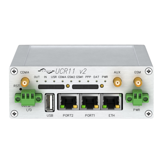
ROUTER DESCRIPTION User interfaces (connectors) 5.7. On the front panel is located: Label Connector Description 2-pin Connector for connection the power supply adapter. RJ45 Connector for connection into the local computer network. Connector connection equipment over RS232, RS458/422, PORT1 RJ45 ETHERNET, M-BUS, CNT or XC-SW. -
Page 16: Status Indication
ROUTER DESCRIPTION Status indication 5.7.1. About router status inform eight led indicators on the front panel and on every port are two LED indicators, which inform about port status. Label Color State Description Blinking Router is ready Green Starting of the router Blinking Communication in progress 1x flash per... -
Page 17: Power Connector Pwr
ROUTER DESCRIPTION Power connector PWR 5.7.2. Panel socket 2-pin. Signal Description number mark VCC (+) Positive pole of DC supply voltage (+10 to +30 VDC) GND (-) Negative pole of DC supply voltage Table 8: Connection of power connector Fig. 17: Power connector Power supply for router is required between +10 V to +30 V DC supply. -
Page 18: Antenna Connector Cdma, Umts And Aux
ROUTER DESCRIPTION Antenna connector CDMA, UMTS and AUX 5.7.3. All of these antennas are connected to the router using the SMA connectors on the front panel. The router can not operate without the CDMA and UMTS antennas connected. CDMA and UMTS connectors used to connect CDMA and UMTS antennas. To connect the third antenna for diversity income is used third connector AUX. -
Page 19: Sim Card Reader
ROUTER DESCRIPTION SIM card reader 5.7.4. The SIM card reader for 3 V and 1.8 V cards is located on the front panel of the router. To initiate the router into operation it is necessary to insert an activated SIM card with unblocked PIN in the reader. -
Page 20: Fig. 24: Connection Ethernet Cable
ROUTER DESCRIPTION Ethernet cable plug into the RJ45 connector labeled as ETH (see figure bellow). Fig. 24: Connection Ethernet cable The ETH router connection: Fig. 25: Example of router connection... -
Page 21: Port1
ROUTER DESCRIPTION PORT1 5.7.6. The PORT1 is equipped with one of the offered options ports. For PORT1 are available on the interface. PORT1 RS232, RS485/422, ETHERNET, M-BUS, CNT, XC-SW (together with PORT2) Description, connection and examples of expansion connection ports can be found in separate manuals expansion ports. -
Page 22: Usb Port
ROUTER DESCRIPTION USB port 5.7.8. Panel socket USB-A. Signal mark Description Data flow direction number Positive pole of 5V DC supply voltage USB data - USB data signal – negative pole Input/Output USB data + USB data signal – positive pole Input/Output Negative pole of DC supply voltage Table 10: Connection of USB connector... -
Page 23: I/O Port
ROUTER DESCRIPTION I/O port 5.7.9. Panel socket 3pin. Signal Description Data flow direction mark BIN0 Binary input Input Signal ground OUT0 Binary output Output Table 11: Connection of I/O port Fig. 31: I/O connector The user interface I/O is for processing of binary input signal and to control (settings) of binary output signal. -
Page 24: Reset
ROUTER DESCRIPTION Reset 5.7.10. It is important to distinguish between reset and reboot the router. Action Router behavior Invoking events Disconnect and connect the power. Reboot Turn off and then turn on router Press the reboot button in the web configuration. -
Page 25: Connecting The Router Before First Use
ROUTER DESCRIPTION 6. First use Connecting the router before first use 6.1. Before you give up the router, it is necessary to connect all components needed for the operation of your applications and the SIM card must be inserted. (See bellow picture) The router can not operate without connected antenna, SIM card and power supply. -
Page 26: Start Router
ROUTER DESCRIPTION Start router 6.2. The router is set up connecting the power supply to the router. In the default setting the router starts to login automatically to the preset APN. Device on the Ethernet port DHCP server will assign addresses. The behavior of the router can be modified by means of the web or Telnet interface, which is described in the configuration manual. -
Page 27: Technical Parameters Of Router
TECHNICAL PARAMETERS 7. Technical parameters Technical parameters of router 7.1. UCR11 v2 EN 301 511, v9.0.2, EN 301 908-1&2, v3.2.1, Complies with standards ETSI EN 301 489-1 V1.8.1, EN 60950-1:06 ed.2 + A11:09 + A1:10 Function C to +60 Temperature range... -
Page 28: Technical Parameters Of Cdma Module
TECHNICAL PARAMETERS Technical parameters of CDMA module 7.3. CDMA module Data rate 3,1 Mbps/1,8 Mbps CDMA2000 1x EV-DO Rev.A CDMA parameters Backward compatible with: CDMA2000 1x EV-DO Rev.0 Transmit power +23.0 dBm ~ +30.0 dBm 450MHz (Sub band A,B,L) / Support band 800MHz &... -
Page 29: Recommended Literature
8. Recommended literature [1] Conel: Start guide, [2] Conel: Configuration manual, [3] Conel: User’s manual – Expansion port RS232, [4] Conel: User’s manual – Expansion port RS485/RS422, [5] Conel: User’s manual – Expansion port M-BUS, [6] Conel: User’s manual – Expansion port CNT, [7] Conel: User’s manual –... -
Page 30: Faq
10. FAQ I can’t get from internet on equipment, which is connected to router and I have NAT enabled. The device's gateway has to be configured as the router. Router resets itself, connection on Ethernet fails. It is necessary to use an antenna, which will be situated far from power supply. - Page 31 RS232 doesn’t function. It is necessary to verify present the expansion port RS232. Verify present the expansion port RS232 in router configuration in menu „external port“, or verify connection locally by the help Telnet-Hyper terminal. L2TP or IPSec isn’t establishing. ...
-
Page 32: Customers Support
During cleaning of the router do not use aggressive chemicals, solvents and abrasive cleaners! Conel Company hereby declares that the router narrated in this user’s guide fits all basic demands of directive 1999/5/EC (R&TTE). Router fits values of coefficient SAR defined by association ICNIRP and values of “About protection of health before non-ionized radiation“.
Need help?
Do you have a question about the UCR11 v2 SL and is the answer not in the manual?
Questions and answers