
Related Manuals for Conel SPECTRE v3 LTE


Summary of Contents for Conel SPECTRE v3 LTE
- Page 1 WWW.INFOPULSAS.LT / info@infopulsas.lt Cellular router SPECTRE v3 LTE USER’S MANUAL...
- Page 2 Information, notice – information, which contains useful advice or special interest. GPL License Source codes under GPL license are available free of charge by sending an email to: info@conel.cz. Conel s.r.o., Sokolska 71, 562 04 Usti nad Orlici, Czech Republic Manual Rev. 1 issued in CZ, December 1, 2014...
-
Page 3: Table Of Contents
CONTENTS Contents 1 Safety Instruction 2 Product Disposal Instructions 3 Router Description 3.1 Usage of the Router ....... . . 4 Contents of Package 5 Router Design 5.1 Router versions . - Page 4 CONTENTS 7.1 Technical parameters of router ......7.2 Technical parameters of module ......7.3 Technical parameters of GPS .
- Page 5 Removing from the DIN rail ......SPECTRE v3 LTE front panel ......
- Page 6 LIST OF FIGURES Router web interface ....... . .
-
Page 7: List Of Tables
LIST OF TABLES List of Tables Router versions ........Delivery identification . -
Page 8: Safety Instruction
1. SAFETY INSTRUCTION 1. Safety Instruction Please, observe the following instructions: The router must be used in compliance with all applicable international and national laws and in compliance with any special restrictions regulating the utilization of the router in prescribed applications and environments. To prevent possible injury to health and damage to appliances and to ensure that all the relevant provisions have been complied with, use only the original accessories. -
Page 9: Product Disposal Instructions
2. PRODUCT DISPOSAL INSTRUCTIONS 2. Product Disposal Instructions The WEEE (Waste Electrical and Electronic Equipment: 2002/96/EC) directive has been introduced to ensure that electrical/electronic products are recycled using the best available recovery techniques to minimize the impact on the environment. This product contains high quality materials and components which can be recycled. -
Page 10: Router Description
V and 1.8 V SIM cards, which are placed on the rear panel of the router. An integral part of the router is also a memory card reader. This reader allows SPECTRE v3 LTE to operate with microSD cards and increase storage space of the router up to 64 GB (32 GB in case of SDHC cards). -
Page 11: Usage Of The Router
3. ROUTER DESCRIPTION 3.1 Usage of the Router The router is primarily intended for these four basic situations: I. Access to the Internet from LAN Figure 1: Access to the Internet from LAN II. Backed up access to the Internet (from LAN) Figure 2: Backed up access to the Internet... -
Page 12: Using Vpn Tunnel
3. ROUTER DESCRIPTION III. Secure networks interconnection or using VPN Figure 3: Using VPN tunnel IV. Serial Gateway Figure 4: Serial Gateway... -
Page 13: Contents Of Package
4. CONTENTS OF PACKAGE 4. Contents of Package Basic delivered set of router includes: router, power supply, crossover UTP cable, up to three external antennas, loose power and I/O connector (+8 pins clip for the DIN rail, paper start guide. Figure 5: Contents of package These pins are designed for cables with a diameter from 0.2 to 0.8 mm 2... -
Page 14: Router Design
5. ROUTER DESIGN 5. Router Design 5.1 Router versions SPECTRE v3 LTE router is supplied in the following versions (see table below). All versions are available in plastic or metal box according to customer requirements. Router versions BOUT WiFi Basic version... -
Page 15: Delivery Identification
Ordering codes overview is shown in the table below. Name Order code Features – interfaces SPECTRE v3 LTE set SR303000xy LTE module PLS8, 2x ETH, 1x USB, 2x BI, 1x BO, 1x microSD reader, 2x SIM reader SPECTRE v3 LTE set... -
Page 16: Type Of Router Box
5. ROUTER DESIGN Continued from previous page Name Order code Features – interfaces SPECTRE v3 LTE set SR303001xy LTE module PLS8, 5x ETH, 1x USB, 2x BI, 1x BO, 1x microSD reader, 2x SIM reader SPECTRE v3 LTE set SR303101xy... -
Page 17: Basic Dimensions Of Router Box
5. ROUTER DESIGN 5.4 Basic dimensions of router box Figure 14: Basic dimensions of router box 5.5 Mechanical dimensions and mounting recommendations Mounting recommendations: possibility to be put on a work surface, DIN rail with clips CPD3 (or CKD3 for metal version) are included. For the most of applications with a built-in router in a switch board it is possible to recognize two kinds of environments: no public and industry environment of low voltage with high interference,... -
Page 18: Removing From The Din Rail
5. ROUTER DESIGN 5.6 Removing from the DIN rail Default position of CPD3 holder (or CKD3 holder for metal version), which is used for mounting the router on a DIN rail, is shown in the following figure: Figure 15: Default position of DIN holder For removing from the DIN rail it is necessary to lightly push upward the router so that the top part of the CPD3 holder (or CKD3 for metal version) hitched to the DIN rail get out of this rail and then fold out the top part of the router away from the DIN rail. -
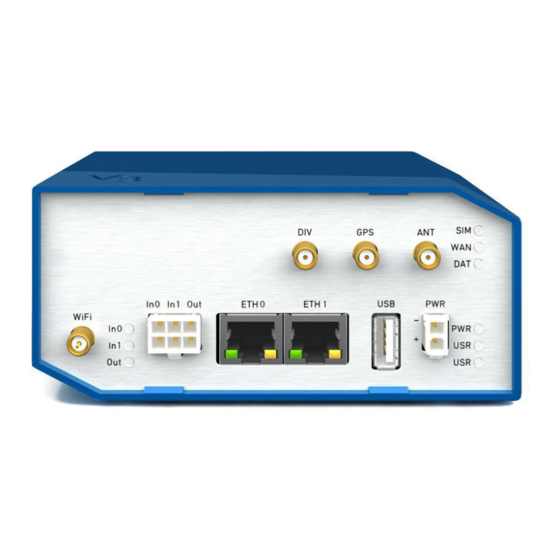
Page 19: Description Of The Rear Panel
Connector for connection of USB devices to the router. Sup- Host ports devices with PL-2303 and FTDI USB/RS232 converters. 6-pin Connector for connection of the binary input and output. Table 7: Front panel description Figure 17: SPECTRE v3 LTE front panel... -
Page 20: Status Indication
5. ROUTER DESIGN 5.8.1 Status indication About router status inform nine LED indicators on the front panel. Each ETH port has two additional LEDs that provide information about port status. Caption Color State Description Green Blinking Router is ready Starting of the router Fast blinking Updating firmware Yellow... -
Page 21: Power Connector Pwr
Power supply for router is required between +10 V to +60 V DC supply. Protection against reversed polarity without signaling is built into the router. SPECTRE v3 LTE can be put into low power mode using a special command. Router can be awakened for example by an activity on binary input. -
Page 22: Antenna Connector Ant, Div, Gps And Wifi
5. ROUTER DESIGN 5.8.3 Antenna connector ANT, DIV, GPS and WIFI Main, diversity and GPS antennas are connected to the router using the SMA connector on the front panel. There is also available R-SMA antenna connector through which the additional antenna can be connected, if the router is equipped with WiFi module. -
Page 23: Sim Card Reader
5. ROUTER DESIGN 5.8.4 SIM card reader Two SIM card readers for 3 V and 1.8 V SIM card are placed on the rear panel of the router. For getting the router to work is necessary to insert an activated SIM card with an unblocked PIN code. The SIM cards might be of different adjusted APN (Access Point Name). -
Page 24: Ethernet Port (Eth0 And Eth1)
5. ROUTER DESIGN Changing the microSD card: Use the flat end of a spudger, or your fingernail, to press the microSD card slightly deeper into its slot until you hear a click. After the click, release the card and it will pop out of its slot. Remove the microSD card and push any other microSD card into the slot until it clicks in place. -
Page 25: Usb Port
5. ROUTER DESIGN Figure 25: Connection of ethernet cable The insulation strength is up to 1.5 kV. 5.8.7 USB Port Panel socket USB-A. Signal mark Description Data flow direction +5 V Positive pole of 5 V DC supply voltage USB data - USB data signal –... -
Page 26: I/O Port
5. ROUTER DESIGN 5.8.8 I/O Port Panel socket 6-pin. Signal mark Description Binary input 0 Binary input 0 Binary input 1 Binary input 1 Binary output Binary output Table 13: Connection of I/O port Figure 27: I/O connector I/O user Interface is designed for processing of binary input and control (setting) binary output. Bi- nary output is open in the default configuration. -
Page 27: Binary Inputs Connection
5. ROUTER DESIGN Binary inputs connection with example: Figure 28: Binary inputs connection Binary output Binary output parameters: – 60 V AC / 300 mA – 60 V DC / 300 mA Current of binary output is limited by a resettable fuse (300 mA). Binary output connection with example: Figure 29: Binary output connection... -
Page 28: Reset
5. ROUTER DESIGN 5.8.9 Reset When PWR LED starts flashing on the front panel, it is possible to restore the default configuration of the router by pressing the RST button on the rear panel. After pressing this button the default configuration is restored and then router reboots (green LED will be on). -
Page 29: Interfaces Description
5. ROUTER DESIGN 5.9 Interfaces description Besides the basic version of SPECTRE v3 router there are available versions with one of the following interfaces: RS232 interface RS232-RS485/422 interface SWITCH interface 5.9.1 RS232 interface This interface is physically connected on RJ45 connector. RS232 converter is protected against overload the bus. -
Page 30: Rs232 Connector
5. ROUTER DESIGN Figure 32: RS232 connector Example of a meter connection to router: Figure 33: Meter connection to router State indication of RS232 port: Description of indication Green LED Indicates Receive data Yellow LED Indicates Transmit data Table 17: State indication of RS232 port Technical specifications: RS232 interface Power supply... -
Page 31: Rs232-Rs485/422 Interface
5. ROUTER DESIGN 5.9.2 RS232-RS485/422 interface These interfaces are physically connected on five-pin and four-pin terminal block connectors. The insulation strength is up to 2.5 kV. Attention, connectors are not isolated from each other! Figure 34: Version with RS232-RS485/422 interface Connection of RS232 connector: Signal Description... -
Page 32: Rs485/422 Connector
5. ROUTER DESIGN Connection of RS422 connector: Signal Description Direction RxD- Receive data (-) Output RxD+ Receive data (+) Output TxD- Transmit data (-) Input TxD+ Transmit data (+) Input Table 21: Connection of RS422 connector Figure 36: RS485/422 connector Selection of RS485 or RS422 can be performed using jumpers on the board. -
Page 33: Switch Interface
5. ROUTER DESIGN 5.9.3 SWITCH interface Three LAN ports of SWITCH interface intended for v3 routers (RJ-45 connectors for connecting ethernet devices) act as it is a typical switch device. This means that the router with internal switch desk reads ethernet frames (a data packets on an ethernet link) from any port and transmits them on other ports of the switch board. -
Page 34: First Use
6. FIRST USE 6. First Use 6.1 Connecting the router before first use Before putting the router into operation it is necessary to connect all components which are required to run your applications. Don’t forget to insert SIM card. The router can not operate without connected antenna, SIM card and power supply. If the antenna is not connected, router can be demaged. -
Page 35: Start
6. FIRST USE 6.2 Start The router is put into operation when the power supply is connected to this router. By default, the router will automatically start to log on to the default APN. DHCP server will start to assign addresses for devices on the Ethernet port ETH0. - Page 36 6. FIRST USE Figure 42: Router web interface A detailed description of the router settings via the Web interface can be found in the document Con- figuration manual for v3 routers.
-
Page 37: Technical Parameters
7. TECHNICAL PARAMETERS 7. Technical Parameters 7.1 Technical parameters of router SPECTRE v3 LTE Complies with standards EN 301 511, v9.0.2, EN 301 908-1 & -2: v3.2.1, ETSI EN 301 489-1 V1.8.1, EN 60950-1:06 ed.2 + A11:09 + A1:10 Temperature range... -
Page 38: Technical Parameters Of Gps
7. TECHNICAL PARAMETERS Continued from previous page LTE module GPRS/EDGE parameters Bit rate 237 kbps (DL) / 59,2 kbps (UL) GPRS multislot class 10, CS 1 to 4 EDGE multislot class 12, CS 1 to 4, MCS 1 to 9 Supported channels: 900 / 1800 / 1900 MHz Supported GPRS/EDGE EGSM 900: Class 4 (33 dBm) -
Page 39: Characteristics Of Inputs
7. TECHNICAL PARAMETERS 7.4 Technical parameters I/O port Characteristics of inputs: logical 0 / 1 Voltage Current log. 0 max 0.4 mA log. 1 min 0.7 mA log. 1 type 12 V 2 mA log. 1 max 60 V 7 mA Table 25: Characteristics of inputs Binary output parameters: –... -
Page 40: Recommended Literature
8. RECOMMENDED LITERATURE 8. Recommended Literature Conel: Start guide, Conel: Configuration manual. -
Page 41: Troubleshooting
9. TROUBLESHOOTING 9. Troubleshooting Some network cards are able to be set in situation, when it is not possible to connect the router. It is possible to solve this problem in the following steps: hand by selection communication rates 10 MB/s in property network cards, connect router over switch, start computer only after finalizing the start of the router. - Page 42 10. FAQ 10. FAQ I can’t get from internet on equipment, which is connected to router and I have NAT enabled. The device’s gateway has to be configured as the router. Router resets itself, connection on Ethernet fails. It is necessary to use an antenna, which will be situated far from power supply. I don’t get on web server at NAT.
- Page 43 10. FAQ The operator doesn’t give out address DNS servers and without DNS server’s it is impossi- ble to connect to server dyndns.org. In log system will be this message: – DynDNS daemon started – Error resolving hostname: no such file or directory –...
-
Page 44: Customers Support
During cleaning of the router do not use aggressive chemicals, solvents and abrasive cleaners! Conel Company hereby declares that the router narrated in this user’s guide fits all basic demands of directive 1999/5/EC (R&TTE).
Need help?
Do you have a question about the SPECTRE v3 LTE and is the answer not in the manual?
Questions and answers