Table of Contents
Advertisement
Advertisement
Table of Contents

Related Manuals for Conel UR5 v2


Summary of Contents for Conel UR5 v2
- Page 1 UR5 v2 UMTS router UR5 v2 SL USER’S GUIDE...
-
Page 2: Table Of Contents
2.14. Putting into operation 2.15. Mechanical external dimensions and mounting recommendations Expansion port mounting 3.1. Expansion port mounting for UR5 v2 3.2. Expansion port mounting for UR5 v2 SL Changing the SIM cards Ordering code routers 5.1. Basic version 5.2. - Page 3 CONTENTS 6.13. IPSec Tunnel Configuration 6.14. GRE Tunnels Configuration 6.15. L2TP Configuration 6.16. DynDNS Client Configuration 6.17. NTP Client Configuration 6.18. SNMP Configuration 6.19. SMTP Configuration 6.20. SMS Configuration 6.21. Expansion Port Configuration 6.22. USB Port Configuration 6.23. Startup Script 6.24.
- Page 4 Source codes under GPL licence are available free of charge by sending an email to info@conel.cz. Declared quality system ISO 9001 Conel s.r.o., Sokolska 71, 562 04 Usti nad Orlici, Czech Republic Issue in CZ, 5/16/2011 - 4 - 16.5.2011...
-
Page 5: Safety Instruction
SAFETY INSTRUCTION 1. Safety instruction Please, observe the following instructions: The communication module must be used in compliance with all applicable international and national laws and in compliance with any special restrictions regulating the utilization of the communication module in prescribed applications and environments. To prevent possible injury to health and damage to appliances and to ensure that all the relevant provisions have been complied with, use only the original accessories. -
Page 6: Description Of The Router
UMTS router about RS232, RS485/RS422, ETHERNET, M-BUSD or CNT (I/O module). The UMTS router has two versions. The first version is basic UR5 v2 and the second version is UR5 v2s SL in the aluminum box. -
Page 7: Umts Technology
EXPANSION PORT MOUNTING 2.2. UMTS technology For radio terrestrial part UMTS (Universal Mobile Telecommunication System), which is marked as UTRA (UMTS Terrestrial Radio Access), is warranted 155 MHz band in frequency band about the 2 GHz. It is bands 1900–1980 MHz, 2010–2025 MHz and 2110–2170 MHz. The UMTS system is based on code division of carried channels –... -
Page 8: Delivery Identification
Specimen Label: Trade name Type name Other UR5 v2 Basic UR-5-v2 Basic version UR5 v2 SL Basic UR-5-v2-SL Basic version in the aluminum box UR5 v2 Full UR-5-v2-Full Full version UR5 v2 SL Full UR-5-v2-SL-Full Full version in the aluminum box... -
Page 9: Antenna Connection
PORT2 RS232, RS485/422, M-BUSD The router standard designed for: mounting to a panel using through holes (only UR5 v2 version), possibility to be put on a work surface, for mounting onto a DIN rail, the clips are included. 2.5. Antenna Connection The antenna is connected to the router using the SMA connector on the front panel. -
Page 10: Sim Card Reader
3,5 W (GPRS transmission) UMTS/HSDPA to 5,5 W (UMTS/HSDPA transmission) Dimensions 42x76x113 mm (DIN 35mm) Weight UR5 v2 – 150 g UR5 v2 SL – 280 g Antenna connector SMA– 50 Ohm User interface Ethernet (10/100 Mbit/s) USB 2.0 type A host PORT1... -
Page 11: Description Of The Individual Components Of The Router
EXPANSION PORT MOUNTING 2.9. Description of the individual components of the router 2.9.1. UMTS module The UMTS module is used for HSDPA/UMTS/EDGE/GPRS UMTS network wireless communication. It is integrated in the printed circuit board. The slide-out SIM card reader is accessible from the front panel. -
Page 12: User Interfaces (Connectors)
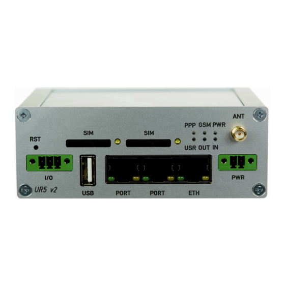
USB-A Host connector (USB) – for connection of the devices to the router, USB supports equipments with PL-2303 and FTDI USB/RS232 converter One MRT 3pin connector (I/O) – for connection of the binary input and output Front panel UR5 v2 SL Front panel UR5 v2... -
Page 13: Connection Of The Pwr Supply Connector
EXPANSION PORT MOUNTING 2.10.1. Connection of the PWR Supply Connector Panel socket MRT 2pin. Signal Description number mark Positive pole of DC supply voltage (+10 to +30 VDC) Negative pole of DC supply voltage Circuit example: Pin 1 – +UN Router Pin 2 –... -
Page 14: Connection Of The Port1 Connector - Rs232
EXPANSION PORT MOUNTING 2.10.3. Connection of the Port1 Connector – RS232 Panel socket RJ45 (RS232 – DCE – Data Communication Equipment). Signal Description Data flow direction number mark Request To Send Input Clear To Send Output Data Terminal Ready Input Data Set Ready –... -
Page 15: Connection Of The Port1 Connector - Rs485
EXPANSION PORT MOUNTING 2.10.4. Connection of the Port1 Connector – RS485 Panel socket RJ45. Signal Description Data flow direction number mark Signal and supply ground Signal and supply ground TxRx- RS485 B (-) Input/Output TxRx+ RS485 A (+) Input/Output TxRx- RS485 B (-) Input/Output TxRx+... -
Page 16: Connection Of The Port1 Connector - Rs422
EXPANSION PORT MOUNTING 2.10.5. Connection of the Port1 Connector – RS422 Signal Description Data flow direction number mark SGND Signal and power supply ground SGND Signal and power supply ground RxD- Receive Data (-) Output RxD+ Receive Data (+) Output TxD- Transmit Data (-) Input... -
Page 17: Connection Of The Port1 Connector - M-Busd
EXPANSION PORT MOUNTING 2.10.6. Connection of the Port1 Connector – M-BUSD Panel socket RJ45. Signal Description Data flow direction number mark Signal and supply ground Signal and supply ground TxRx- M-BUS B (-) Input/Output TxRx+ M-BUS A (+) Input/Output TxRx- M-BUS B (-) Input/Output TxRx+... -
Page 18: Connection Of The Port1 Connector - Cnt
EXPANSION PORT MOUNTING 2.10.7. Connection of the Port1 Connector – CNT Panel socket RJ45. Signal mark Description Data flow direction number BIN1/CNT1 Binary input/counter input Input BIN2/CNT2 Binary input/counter input Input BIN3 Binary input Input BIN4 Binary input Input Signal ground OUT1 Binary output (open collector) Output... -
Page 19: Connection Of The Eth Connector
EXPANSION PORT MOUNTING 2.10.8. Connection of the ETH Connector Panel socket RJ45. Signal mark Description Data flow direction number TXD+ Transmit Data – positive pole Input/Output TXD- Transmit Data – negative pole Input/Output RXD+ Receive Data – positive pole Input/Output RXD- Receive Data –... -
Page 20: Technical Specification Of Optional Port1 And Port2
EXPANSION PORT MOUNTING 2.11. Technical specification of optional PORT1 and PORT2 Expansion port RS232 Expansion port RS232 Power supply Internal ..Environment Operating temperature -20 .. +55 ° C Storage temperature -20 .. +85 ° C Standards Emission EN 55022/B Immunity ETS 300 342 Safety... - Page 21 EXPANSION PORT MOUNTING Interface behaviour of module Expansion port RS485/RS422 can be made by wiring jumpers J4, J5 and J6 on this module. If RS485 is required, jumpers J4 and J5 must be connected and jumper J6 disconnected. If RS422 is required, jumpers J4 and J5 must be disconnected and jumper J6 connected.
- Page 22 EXPANSION PORT MOUNTING Expansion port ETHERNET Expansion port ETH Power supply Internal ..Environment Operating temperature -30 .. +60 ° C Storage temperature -30 .. +85 ° C Standards Emission EN 55022/B Immunity ETS 300 342 Safety EN 60950 Ethernet Max.
- Page 23 EXPANSION PORT MOUNTING Expansion port CNT Expansion port CNT Power supply Internal …. Sleep 100 µA (counter is functional) Operation 2 mA Environment Operating temperature -30 .. +60 ° C Storage temperature -30 .. +85 ° C Standards Emission EN 55022/B Immunity ETS 300 342 Safety...
-
Page 24: Technical Specification Of I/O Port
EXPANSION PORT MOUNTING 2.12. Technical specification of I/O port Port IO Input/Output Binary input reed contact with trigger level 1,3 up to 1,4 V Binary output 120 mA/max. 30 V 2.13. Modem status indication On the front and back panel of the modem there are altogether eight LED indicators, which inform on the modem status. -
Page 25: Putting Into Operation
EXPANSION PORT MOUNTING 2.14. Putting into operation Before putting the UR5 v2 or UR5 v2 SL router into operation it is necessary to connect all components needed for the operation of your applications and the SIM card must be inserted (the modem is off). - Page 26 EXPANSION PORT MOUNTING For the majority of applications with a built-in modem in a switch board it is possible to recognize two sorts of environments: no public and industry environment of low voltage with high interference, public environment of low voltage without high interference. For both of these environments it is possible to mount modems to a switch board, the following there is no need to have examination immunity or issues in connection with EMC according to EN 60439-1 ed.2:00 + A1:04.
- Page 27 EXPANSION PORT MOUNTING for single cables we recommend to bind the bunch according to the following picture, for this use we recommend: length of the bunch (combination of power supply and data cables) can be maximum 1,5 m, if the length of data cables exceeds 1,5 m or in the event of, the cable leads towards the switch - board, we recommend installing over - voltage protectors (surge suppressors), with data cables they mustn't carry cables with reticular tension...
- Page 28 EXPANSION PORT MOUNTING the circuit diagram of the modem is on the following pictures.
-
Page 29: Expansion Port Mounting
Expansion port mounting 3.1. Expansion port mounting for UR5 v2 Attention! Expansion port PORT1 and PORT2 include when the router UR5 v2 SL is switched off. After removing front head of the box it is possible to take out the B-RB-v2 motherboard (position 1). - Page 30 EXPANSION PORT MOUNTING Parts list and description Part Description Number UMTS router motherboard Expansion port PORT1 Expansion port PORT2 Front head Spacers for expansion port PORT1 mounting to motherboard...
-
Page 31: Expansion Port Mounting For Ur5 V2 Sl
EXPANSION PORT MOUNTING 3.2. Expansion port mounting for UR5 v2 SL Attention! Expansion port PORT1 and PORT2 include when the router UR5 v2 SL is switched off. After unscrewing four screws (position 11) on the rear panel (position 6) and removing it is possible to take out the B-RB-v2 motherboard (position 1). The expansion port PORT1 (position 2) is connected to connector J8 (see below) of the router B-RB-v2 motherboard (position 1) from TOP side. - Page 32 EXPANSION PORT MOUNTING Parts list and description Part Description Number UMTS router motherboard Expansion port PORT1 Expansion port PORT2 Left box part Right box part Rear head Front head Bottom box part Top box part Spacers for expansion port PORT1 mounting to motherboard Screw for box completion...
-
Page 33: Changing The Sim Cards
CHANGING THE SIM CARD 4. Changing the SIM cards Attention! Insert the SIM card when the router is switched off. Changing the first SIM card: Ensure that the modem is disconnected from the power supply. Press the small yellow button next to the reader to eject the reader holder. Insert the SIM card into the reader holder and slide it in the reader. -
Page 34: Ordering Code Routers
ORDERING CODE 5. Ordering code routers 5.1. Basic version Basic version includes one Ethernet port, one USB – Host interface, one SIM card reader, one I/O interface and one optional port: Optional port Ordering code Version without optional port UR5 v2B set Version with optional Ethernet port UR5 v2B set ETH Version with optional RS232 port... -
Page 35: Configuration Settings Over Web Browser
CONFIGURATION 6. Configuration settings over web browser Attention! If the SIM card is not inserted in the router, then it is impossible to operate. The inserted SIM card must have activated GPRS. Insert the SIM card when the router is switched-off. Monitoring of the status, configuration and administration of the router can be performed by means of the web interface, which is available after insertion of IP address of the modem into the web browser. -
Page 36: Network Status
CONFIGURATION 6.1. Network Status view system information about modem operation, select the System Information menu item. The bottom part of the window contains information about the system memory usage. The upper part of the window displays detailed information about active interfaces: eth0 –... -
Page 37: Dhcp Status
CONFIGURATION 6.2. DHCP Status Information about IP addresses, which was leased to the router by the DHCP server, is possible to find in menu in sum DHCP: lease 192.168.1.2 (generally IP address) – assigned IP address starts – information about time of assignation of IP address ends –... -
Page 38: Ipsec Status
CONFIGURATION 6.4. IPsec status Information on actual IPsec tunnel state can be called up in option IPsec in the menu. Detailed information on the description shown below can be found on the following link http://www.freeswan.org/doc.html. -
Page 39: Dyndns Status
CONFIGURATION 6.5. DynDNS status DynDNS up - dating entry result on server www.dyndns.org can be called up in option DynDNS item in the menu. 6.6. System Log In case of any problems with connection to GPRS it is possible to view the system log by pressing the System Log menu item. -
Page 40: Lan Configuration
CONFIGURATION 6.7. LAN Configuration To enter the network configuration, select the LAN menu item. In the first part of the window possible define network interface address (IP address), the network mask (Subnet Mask) and media type (Media Type), in the majority of cases set Auto-Negotiation. - Page 41 CONFIGURATION Example of the network interface with dynamic DHCP server: 192.168.1.2 GSM/GPRS 192.168.1.1 192.168.1.3 192.168.1.4...
- Page 42 CONFIGURATION Example of the network interface with dynamic and static DHCP server: 192.168.1.2 192.168.1.3 192.168.1.4 GSM/GPRS 192.168.1.1 192.168.1.10 01-23-45-67-89-ab 192.168.1.11 01-54-68-18-ba-7e...
- Page 43 CONFIGURATION Example of the network interface with default gateway and DNS server: 192.168.1.2 192.168.1.3 192.168.1.4 GSM/GPRS 192.168.1.1 192.168.1.20...
-
Page 44: Vrrp Configuration
CONFIGURATION 6.8. VRRP Configuration To enter the VRRP configuration select the VRRP menu item. VRRP protocol (Virtual Router Redundancy Protocol) is a technique, by which it is possible to forward routing from main router to backup router in the case of the main router failure. If the Enable VRRP is checked, then it is possible to set the following parameters. - Page 45 CONFIGURATION Example of the VRRP protocol: Main router Virtual server ID 5 Host priority 255 APN 1 192.168.1.2 192.168.1.1 10.0.1.3 APN 2 Backup router 192.168.1.3 Virtual server ID 5 Host priority 100...
-
Page 46: Umts/Gprs Configuration
CONFIGURATION 6.9. UMTS/GPRS Configuration To enter the GPRS connection configuration select the GPRS menu item. If the Create GPRS connection option is selected, the modem automatically tries to establish GPRS connection after switching-on. In this window it is possible to define Username, Password, authentificate protocol in the GSM network (Authentication), IP address (IP Address) and phone number (Phone Number) for two different APN. - Page 47 CONFIGURATION If parameter Backup SIM card is set to none, then parameters Switch to other SIM card when connection fails, Switch to backup SIM card when roaming is detected and Switch to backup SIM card when data limit is exceeded switch the router to off-line mode. If PPP connection fails, then the parameter Switch to other SIM card when connection fails ensures switch to secondary SIM card or secondary APN of the SIM card.
- Page 48 CONFIGURATION If the Enable PPPoE bridge mode option selected, it activate the PPPoE bridge protocol PPPoE (point-to-point over ethernet) is a network protocol for encapsulating Point- to-Point Protocol (PPP) frames inside Ethernet frames. Allows you to create a PPPoE connection from the device behind router. For example from PC which is connected to ETH port router.
-
Page 49: Firewall Configuration
CONFIGURATION 6.10. Firewall Configuration By the help of a firewall it is possible to set IP addresses from which are possible to remotely access the router. The choice Allow remote access only from specified hosts is given for easier configuration of hosts. In this firewall configuration it is possible to set up to four remote accesses by the help of Source, Source IP Address, Protocol and Target Port. - Page 50 CONFIGURATION Example of the firewall configuration: TCP/1000 10.0.2.123 ICMP 171.92.5.45 142.2.26.54...
-
Page 51: Nat Configuration
CONFIGURATION 6.11. NAT Configuration To enter the Network Address Translation configuration, select the NAT menu item. By checking Send all incoming packets to default server item setting the Default Server item it is possible to put the router into the mode in which all incoming data from GPRS will be routed to the computer with the defined IP address. - Page 52 CONFIGURATION Example of the configuration with one connection equipment on the router: 162.209.13.222 ppp0 10.0.0.1 192.168.1.2 In these configurations it is important to have marked choice of Send all remaining incoming packets it default server, IP address in this case is the address of the device behind the router.
- Page 53 CONFIGURATION Example of the configuration with more connected equipment: SWITCH 162.209.13.222 10.0.0.1:81 ppp0 10.0.0.1 192.168.1.2:80 10.0.0.1:82 10.0.0.1:83 192.168.1.3:80 192.168.1.4:80...
-
Page 54: Openvpn Tunnel Configuration
CONFIGURATION In this configuration equipment wired behind the router defines the address Server IP Address. The router replies, while PING on address of SIM card. Access on web interface of the equipment behind the router is possible by the help of Port Forwarding, when behind IP address of SIM is indicating public port of equipment on which we want to come up. - Page 55 CONFIGURATION set NAT rules to OpenVPN tunnel. By Authenticate Mode it is possible to choose authentication. On choice are none authentication, or by Pre-shared secret which set shared key for both off-side tunnel; or by Username/Password which enable authentication by CA Certificate, Username and Password;...
- Page 56 CONFIGURATION Example of the OpenVPN tunnel configuration: 192.168.1.2 192.168.2.2 ppp0 10.0.0.2 192.168.2.0 tun 0 19.16.2.0 ppp0 10.0.0.1 192.168.1.0 tun0 19.16.1.0 192.168.1.3 OpenVPN tunnel 192.168.2.3 192.168.1.4 192.168.2.4 Default Gateway 192.168.1.1 Default Gateway 192.168.2.1 OpenVPN tunnel configuration: Protocol UDP Port 1194 1194 Remote IP Address: 10.0.0.2 10.0.0.1...
-
Page 57: Ipsec Tunnel Configuration
CONFIGURATION 6.13. IPSec Tunnel Configuration IPsec tunnel configuration can be called up by option IPsec item in the menu. IPsec tunnel allows protected connection of two networks LAN to the one which looks like one homogenous. In the IPsec Tunnels Configuration window are four rows, each row for one configured IPSec tunnel. - Page 58 CONFIGURATION...
-
Page 59: Gre Tunnels Configuration
CONFIGURATION Example of the IPSec Tunnel configuration: 192.168.1.2 192.168.2.2 ppp0 10.0.0.2 192.168.2.0 ppp0 10.0.0.1 192.168.1.0 192.168.1.3 IPSec tunel 192.168.2.3 192.168.1.4 192.168.2.4 Default Gateway 192.168.1.1 Default Gateway 192.168.2.1 IPsec tunnel configuration: Remote IP Address: 10.0.0.2 10.0.0.1 Remote Subnet: 192.168.2.0 192.168.1.0 Remote Subnet Mask: 255.255.255.0 255.255.255.0 Local Subnet:... - Page 60 CONFIGURATION The tunnels are active after selecting Create x GRE tunnel. In the singles window it is possible to define the IP address of the remote side of the tunnel (Remote External IP Address), internal IP address of the local side of the tunnel (Local Internal IP Address), internal IP address of the remote side of the tunnel (Remote Internal IP Address), address of the network behind the remote side of the tunnel (Remote Subnet) and the mask of the network behind the remote side of the tunnel (Remote Subnet Mask).
-
Page 61: L2Tp Configuration
CONFIGURATION 6.15. L2TP Configuration To enter the L2TP tunnels configuration, select the L2TP menu item. L2TP tunnel allows protected connection by password of two networks LAN to the one which it looks like one homogenous. The tunnels are active after selecting Create L2TP tunnel. In the window it is possible to define L2TP tunnel mode (Mode) on the router side, in case of client IP address of server (Server IP Address), start IP address in range, which is offered by server to clients (Client Start IP Address), end IP address in range, which is... - Page 62 CONFIGURATION Example of the L2TP Tunnel configuration: 192.168.1.2 192.168.2.2 ppp0 10.0.0.2 192.168.2.1 ppp0 10.0.0.1 192.168.1.1 192.168.1.3 L2TP tunel 192.168.2.3 192.168.1.4 192.168.2.4 Default Gateway 192.168.1.1 Default Gateway 192.168.2.1 Configuration of the L2TP tunnel: Mode L2TP Server L2TP Client Server IP Address 10.0.0.1 Client Start IP Address: 192.168.3.2...
-
Page 63: Dyndns Client Configuration
The changes in settings will apply after pressing the Apply button. Example of the DynDNS client configuration with domain conel.dyndns.org, username conel, password conel and default server http://members.dyndns.org: If DNS servers are not assigned by the operator, then it is possible to configure it by inserting of script into start up window: echo “nameserver xxx.xxx.xxx.xxx“... -
Page 64: Ntp Client Configuration
CONFIGURATION 6.17. NTP Client Configuration NTP client Configuration can be called up by option NTP item in the menu. In the window can be defined the address prime (Primary NTP server Address) and secondary NTP server (Secondary NTP server Address), by the help of which the router, after first interface to the GPRS from make power supply, will adjust the inner clock. - Page 65 CONFIGURATION M-BUSD status. Parameters Enable XC-CNT extension and Enable M-BUS extension can not be checked together. Every monitor value is uniquely identified by the help of number identifier OID - Object Identifier. OID is finished by „.9“. For binary input and output the following range of OID is used: Description .1.3.6.1.4.1.30140.2.3.1.0 Binary input BIN0 (values 0,1)
-
Page 66: Smtp Configuration
It is important to set the IP address of the SNMP agent (router) in field Remote SNMP agent. After enter the IP address is in a MIB tree part is possible show object identifier. The path to objects is: iso->org->dod->internet->private->enterprises->conel->protocols. 6.19. SMTP Configuration To enter the SMTP it is possible configure SMTP client. -
Page 67: Sms Configuration
CONFIGURATION E-mail can be send from the Startup skript. This command is used to email with following parameters. receiver Email address subject message appendix number of attempts to send email (default set 2 attempts) Example to send email: email –t name@domain.com –s “subject“ –m “message“ –a c:\directory\abc.doc –r 5 6.20. - Page 68 CONFIGURATION It is possible to send controls SMS in the form: Description go online sim 1 Switch to SIM1 card go online sim 2 Switch to SIM2 card go online Switch router in online mode go offline PPP connection termination set out0=0 Set output I/O connector on 0 set out0=1...
- Page 69 CONFIGURATION...
- Page 70 CONFIGURATION After powering up the router, at introduction of the telephone number comes SMS in the form of: UR5 (Unit ID) has been powered up. PLMN:xxxxx,Cell:xxxx,Channel:xx,Level:-xxdBm. Where PLMN is – number of mobile operator, Cell – number of cell, Channel – used channel, Level –...
- Page 71 CONFIGURATION Example of the router configuration for SMS sending via serial interface:...
- Page 72 CONFIGURATION Example of the router configuration for controlling via SMS from every phone numbers:...
- Page 73 CONFIGURATION Example of the router configuration for controlling via SMS from two phone numbers: The SMS is possible to do for example in HyperTerminal program. After establishing connection with the router via serial interface or Ethernet, it is possible to do with SMS by the help of the next AT commands (more about AT commands see reference [1]): AT commands Description...
- Page 74 CONFIGURATION For the text mode for SMS writing is used command AT+CMGF=1. AT+CMGF=1 Enter The SMS message is created by the help of command AT+CMGS=<tel. number>. After Enter button is pressed is displayed mark >, behind this mark it is possible to write your own SMS message.
-
Page 75: Expansion Port Configuration
CONFIGURATION 6.21. Expansion Port Configuration The expansion port configuration can be called up by airbrush option External Port in menu. Inside the window can be defined Baudrate, number of Data bits, Parity, number of Stop bits, Protocol and Mode. Split timeout is for messages. In mode TCP server it is necessary to enter the TCP port, on which the router will listen to incoming requests about TCP connection. -
Page 76: Usb Port Configuration
CONFIGURATION ppp0 10.0.0.2 RS232 ppp0 10.0.0.1 RS232 Settings in the router Settings in the router Mode: TCP server Mode: TCP client Server Address: - Server Address: 10.0.0.2 TCP Port: 2000 TCP Port: 2000 6.22. USB Port Configuration The USB port configuration can be called up by airbrush option USB Port in menu. Inside the window can be defined Baudrate, number of Data bits, Parity, number of Stop bits, Protocol and Mode. - Page 77 CONFIGURATION Example of USB port configuration: Equipment ppp0 10.0.0.2 ppp0 10.0.0.1 192.168.1.1 192.168.1.100 Settings in application on PC: Settings in the router TCP connection on 10.0.0.2:2000 Mode: TCP server Server Address: - Default Gateway 192.168.1.1 TCP Port: 2000 Equipment ppp0 10.0.0.2 ppp0 10.0.0.1 Settings in the router Settings in the router...
-
Page 78: Startup Script
CONFIGURATION 6.23. Startup Script In the window Startup Script it is possible to create own scripts which will be executed after all initial scripts. This script is not stored or restored when using web interface backup or restores option. The changes in settings will apply after pressing the Apply button. Change take effect after restarting router by the help of button Reboot in web administration or by SMS message. -
Page 79: Up/Down Script
CONFIGURATION 6.24. Up/Down Script In the window Up/Down Script it is possible to create own scripts. In the item Up script is defined scripts, which begins after establishing a PPP connection. In the item Down Script is defines script, which begins after lost a PPP connection. This script is not stored or restored when using web interface backup or restores option. -
Page 80: Change Profile
CONFIGURATION By parameter Base URL it is possible to enter base part of the domain or IP address, from which the configuration file will be downloaded. In the case that Unit ID is empty, the contents of parameter Unite ID or MAC address is added to Base URL. The configuration file name is from parameter Base URL, hardware MAC address of ETH0 interface and cfg extension. -
Page 81: Change Password
CONFIGURATION 6.27. Change password To open the dialog box for changing the access password select the Change Password menu item. The new password will be saved after pressing the Apply button. In basic settings of the router the password is set on default form root. For higher security of your network we recommend changing this password. -
Page 82: Send Sms
CONFIGURATION 6.31. Send SMS Sending SMS messages is possible in menu Send SMS. The SMS message will be sent after entering the Phone number and text SMS (Message) and by pushing button Send. SMS message sending via HTTP request is in the form: GET /send_exec.cgi?phone=%2B420712345678&message=Test HTTP/1.1 Authorization: Basic cm9vdDpyb290 HTTP request will be sent to TCP connection on router port 80 which sends an SMS... -
Page 83: Update Firmware
CONFIGURATION 6.34. Update firmware To view the information about the firmware version and instructions for its update select the Update Firmware menu item. The new firmware will be checked after pressing Browse button and update the following pressing the Update button. After successful firmware updating the following statement is listed: There is information about updating of the FLASH memory. -
Page 84: Default Settings
CONFIGURATION 6.36. Default settings After green LED starts to blink it is possible to restore initial settings of the router by pressing button RST on front panel. After press button RST it is restoration of the configuration and reset (green LED will be on). LAN Configuration 6.36.1. -
Page 85: Vrrp Configuration
CONFIGURATION VRRP Configuration 6.36.2. Firewall Configuration 6.36.3. -
Page 86: Umts/Gprs Configuration
CONFIGURATION UMTS/GPRS Configuration 6.36.4. -
Page 87: Nat Configuration
CONFIGURATION NAT Configuration 6.36.5. -
Page 88: Openvpn Tunnel Configuration
CONFIGURATION OpenVPN Tunnel Configuration 6.36.6. -
Page 89: Ipsec Tunnel Configuration
CONFIGURATION IPsec Tunnel Configuration 6.36.7. -
Page 90: L2Tp Tunnel Configuration
CONFIGURATION GRE Tunnels Configuration 6.36.8. L2TP Tunnel Configuration 6.36.9. DynDNS Configuration 6.36.10. -
Page 91: Ntp Configuration
CONFIGURATION NTP Configuration 6.36.11. SNMP Configuration 6.36.12. SMTP Configuration 6.36.13. -
Page 92: Sms Configuration
CONFIGURATION SMS Configuration 6.36.14. -
Page 93: Expansion Port Configuration
CONFIGURATION Expansion Port Configuration 6.36.15. USB Port Configuration 6.36.16. -
Page 94: Startup Script
CONFIGURATION Startup script 6.36.17. Up/Down Script 6.36.18. -
Page 95: Automatic Update
CONFIGURATION Automatic update 6.36.19. -
Page 96: Configuration Setting Over Telnet
CONFIGURATION 7. Configuration setting over Telnet Attention! If the SIM card isn’t inserted in the router, it is impossible for the router to operate. The Included SIM card must be activated for GPRS transmissions. Insert the SIM card when the router is switched off. Monitoring of status, configuration and administration of the router can be performed by means of the Telnet interface. -
Page 97: Possible Problems
PROBLEMS, KEEPING Possible problems Some network cards are able to be set in situation, when it is not possible to connect the router. It is possible to solve this problem in the following steps: hand by selection communication rates 10 MB/s in property network cards, connect router over switch, start computer only after finalizing the start of the router. -
Page 98: Customers Support
During cleaning of the modem do not use aggressive chemicals, solvents and abrasive cleaners! Conel Company hereby declares that the modem narrated in this user’s guide fits all basic demands of directive 1999/5/EC (R&TTE). Modem fits values of coefficient SAR defined by association ICNIRP and values of “About protection of health before non-ionized radiation“. -
Page 99: Product Disposal Instructions
PROBLEMS, KEEPING 12. Product disposal instructions The WEEE (Waste Electrical and Electronic Equipment: 2002/96/EC) directive has been introduced to ensure that electrical/electronic products are recycled using the best available recovery techniques to minimize the impact on the environment. This product contains high quality materials and components which can be recycled. -
Page 100: Guarantee Claim Guidelines
GUARANTEE 13. Guarantee Claim Guidelines Dear customer, The product that you have purchased was tested by the manufacturer and, before it was sold, the product’s functions were checked once more by our company’s technician. However if, in spite of the above-mentioned measures, a breakdown of this product occurs during the guarantee period, which makes proper utilization of the product impossible, we ask you to observe the Guarantee Claim Guidelines when asserting a guarantee claim. - Page 101 GUARANTEE the exchange of the IMEI), the ownership of the original object of the guarantee claim is passed hereupon onto the seller, and the ownership of the new product, onto the buyer. A new guarantee period starts running from the date of acceptance of the new product. In the event that the seller, upon agreement with the customer, has settled the guarantee claim by exchanging the object of the guarantee claim for a faultless product, the new guarantee of the product shall expire as follows:...
- Page 102 GUARANTEE Other guarantee claim conditions The fact that the object of the guarantee claim does not correspond to parameters that have been set for other similar types of products can not be considered to be a defect. For the assessment whether a defect has occurred, the product parameters included in the technical documentation of the product are decisive.
-
Page 103: Guarantee Certificate
GUARANTEE CERTIFICATE 14. Guarantee certificate Type of the device Serial number Guarantee period (in months) Seller Date of sale Stamp of the seller... - Page 104 GUARANTEE CERTIFICATE Date of reception of the guarantee claim by the seller Number of the guarantee claim report Date of reception of the device into the repair shop Date of completion of the repair by the repair shop Number of the receipt form of the repair shop Guarantee repair...
Need help?
Do you have a question about the UR5 v2 and is the answer not in the manual?
Questions and answers