Table of Contents
Advertisement
WARNING: If the information in this manual is not
followed exactly, a fire or explosion may result causing
property damage, personal injury or loss of life.
— Do not store or use gasoline or other flammable va-
pors and liquids in the vicinity of this or any other
appliance.
— WHAT TO DO IF YOU SMELL GAS
• Do not try to light any appliance.
• Do not touch any electrical switch; do not use any
phone in your building.
• Immediately call your gas supplier from a neighbor's
phone. Follow the gas supplier's instructions.
• If you cannot reach your gas supplier, call the fire
department.
— Installation and service must be performed by a quali-
fied installer, service agency or the gas supplier.
WARNING: This appliance is equipped for Natural and
Propane gas. Field conversion is not permitted other than
between natural or propane gases.
Questions, problems, missing parts? Before returning to your retailer, call
our customer service department at 1-866-573-0674, 8:00 am - 4:30 pm CST,
Monday through Friday or email customerservice@usaprocom.com
VENT-FREE GAS STOVE
OWNER'S OPERATION
AND INSTALLATION
MANUAL
MODELS
PCSD25T
PCSD25RT
PFS
®
US
Advertisement
Table of Contents

Subscribe to Our Youtube Channel
Related Manuals for Procom PCSD25T


Summary of Contents for Procom PCSD25T
- Page 1 VENT-FREE GAS STOVE OWNER’S OPERATION AND INSTALLATION MANUAL MODELS PCSD25T PCSD25RT ® WARNING: If the information in this manual is not followed exactly, a fire or explosion may result causing property damage, personal injury or loss of life. — Do not store or use gasoline or other flammable va- pors and liquids in the vicinity of this or any other appliance.
-
Page 2: Table Of Contents
TABLE OF CONTENTS Safety ............3 Operation ..........17 Qualified Installing Agency ......4 Inspecting Burners........23 Specifications ..........5 Care And Maintenance ......24 Product Features ........5 Troubleshooting ........26 Local Codes..........5 Replacement Parts ........29 Product Identification ......... 6 Accessories .......... -
Page 3: Safety
SAFETY IMPORTANT: Read this owner’s WARNING: Any change to manual carefully and completely this heater or its controls can before trying to assemble, op- be dangerous. erate, or service this heater. Improper use of this heater can WARNING: Do not allow fans cause serious injury or death to blow directly into fireplace. -
Page 4: Qualified Installing Agency
SAFETY 1. Do not place Propane/LP supply tank(s) service technician to inspect the room inside any structure. Propane/LP supply heater and to replace any part of the tank(s) must be placed outdoors. control system and any gas control which has been under water. 2. -
Page 5: Specifications
SAFETY PILOT THERMOSTATIC CONTROL This heater has a pilot with an Oxygen Deple- Model PCSD25T The control automatically tion Sensing (ODS) safety shutoff system. The cycles the burner on and off to maintain a ODS/pilot shuts off the heater if there is not desired room temperature. -
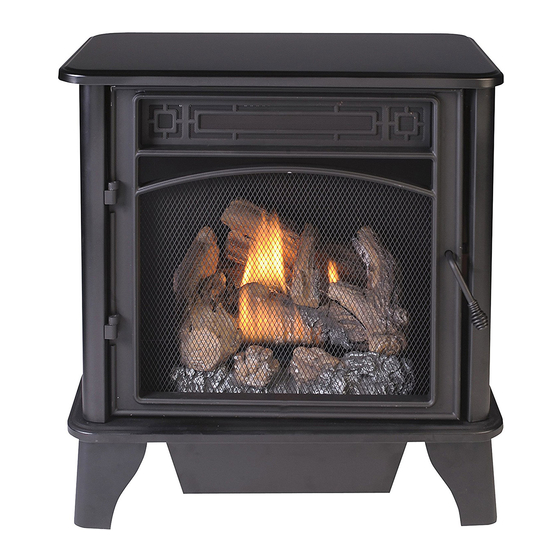
Page 6: Product Identification
PRODUCT IDENTIFICATION Screen Logs Heater Controls (Inside Panel) Figure 1 - Vent-Free Stove UNPACKING 1. Remove top inner pack. 6. Hold the screen, lift, and pull forward. 2. Tilt carton so that heater is upright. 7. Remove log set by cutting plastic ties. 3. -
Page 7: Air For Combustion And Ventilation
AIR FOR COMBUSTION AND VENTILATION heat loss in homes. Home owners weather WARNING: This heater shall strip and caulk around windows and doors not be installed in a confined space to keep the cold air out and the warm air in. or unusually tight construction During heating months, home owners want their homes as airtight as possible. - Page 8 AIR FOR COMBUSTION AND VENTILATION DETERMINING FRESH-AIR FLOW FOR HEATER LOCATION Determining if You Have a Confined or Unconfined Space Use this work sheet to determine if you have 4. Compare the maximum Btu/Hr the space a confined or unconfined space. can support with the actual amount of Btu/ Hr used.
- Page 9 AIR FOR COMBUSTION AND VENTILATION VENTILATION AIR Ventilation Air From Inside Building This fresh air would come from an adjoining 1 and 2, Figure 2). You can also remove door unconfined space. When ventilating to an into adjoining room (see option 3, Figure 2). adjoining unconfined space, you must provide Follow the National Fuel Gas Code, ANSI two permanent openings: one within 12"...
-
Page 10: Installation
INSTALLATION IMPORTANT: Vent-free heaters add moisture NOTICE: This heater is intended to the air. Although this is beneficial, installing for use as supplemental heat. heater in rooms without enough ventilation air Use this heater along with your may cause mildew to form too much moisture. See Air for Combustion and Ventilation, pages primary heating system. - Page 11 INSTALLATION GAS SELECTION 3. Replace cover over fuel selection device This appliance is factory and reinstall screws. preset for propane/LP gas. 4. Remove hex plug (with wrench provided) No changes are required for from natural gas inlet of regulator (see connecting to propane/LP .
- Page 12 INSTALLATION CONNECTING TO GAS SUPPLY WARNING: A qualified ser- CAUTION: For natural gas, vice technician must connect check your gas line pressure heater to gas supply. Follow all before connecting heater to gas local codes. line. Gas line pressure must be no greater than 10.5"...
- Page 13 INSTALLATION For propane/LP installations, apply pipe joint sealant lightly to male threads. This will prevent excess sealant from going into pipe. Excess sealant in pipe could result in clogged heater valves. The installer must supply an external regula- tor. The external regulator will reduce incom- ing gas pressure.
-
Page 14: Checking Gas Connections
INSTALLATION CHECKING GAS CONNECTIONS WARNING: Never use an open WARNING: Test all gas piping flame to check for a leak. Apply and connections for leaks after a noncorrosive leak detection installing or servicing. Correct fluid to all joints. If bubbles form, all leaks at once. - Page 15 INSTALLATION PRESSURE TESTING HEATER GAS CONNECTIONS 1. Open equipment shutoff valve (see Figure 12, page 14). Apply a noncorrosive leak 10, page 14). detection fluid to all joints. Bubbles form- ing show a leak. 2. Open main gas valve located on or near gas meter for natural gas or open pro- 5.
-
Page 16: Installing Logs
INSTALLATION INSTALLING LOGS 6. Place pin on log #5 into hole in the left side WARNING: Failure to posi- of log #1 as shown in Figures 16 and 17, tion the parts in accordance page 17. with these diagrams or failure 7. -
Page 17: Operation
INSTALLATION Hole for Log #5 Hole for Log #7 Log #6 Log #7 Log #5 Log #8 Log #4 Figure 17 - Logs #5, #6 and #7 Figure 16 - Logs #4 and #8 OPERATION FOR YOUR SAFETY READ BEFORE LIGHTING not use any phone in your building. -
Page 18: Lighting Instructions
OPERATION MODEL PCSD25T LIGHTING INSTRUCTIONS pilot with match. To light pilot with match, WARNING: You must operate see Manual Lighting Procedure, page 19. this heater with the door closed 7. Keep control knob pressed in for 30 sec- and in the locked position. Make onds after lighting pilot. - Page 19 OPERATION THERMOSTAT CONTROL OPERATION The thermostatic control used on this model differs from standard thermostats. Standard ther- mostats simply turn the burner on and off. The thermostat used on this heater senses the room temperature. At times the room may exceed the set temperature. If so, the burner will shut off. The burner will cycle back on when room temperature drops below the set temperature.
- Page 20 OPERATION Note: The first time that the heater is 11. Turn control knob counterclockwise operated after connecting the gas supply, to the ON position. The main burner the control knob should be pressed for should light. about thirty (30) seconds. This will allow Note: Please wait one minute after shut- air to bleed from the gas system.
-
Page 21: Remote Control Operation
OPERATION REMOTE CONTROL SYSTEM Programming the Remote and Receiver Install Batteries The remote and receiver must be “learned” Batteries are required in both the Remote to one another. Control (Transmitter) (2 AAA size) and Re- ceiver (4 AA size) (see Figure 20). 1. - Page 22 OPERATION LCD Liquid Crystal Display OFF OPERATION 1. DISPLAY Indicates CURRENT room Press the OFF key and the appliance flame temperature. will shut off. During this time the LCD screen 2. °F or °C Indicates degrees Fahrenheit or will show OF (see Figure 25). Celsius.
-
Page 23: Inspecting Burners
OPERATION REMOTE CONTROL OPERATION NOTES The Thermo Feature on the transmitter op- ROOM temperature, which determines when erates the appliance whenever the ROOM the fireplace will be activated. The transmitter TEMPERATURE varies a certain number of has ON and OFF manual functions that are degrees from the SET TEMPERATURE. -
Page 24: Care And Maintenance
Approx. 3"-6" Above Top of Logs INSPECTING BURNERS BURNER FLAME PATTERN Figure 28 shows a correct burner flame pattern. Figure 29 shows an incorrect burner flame pattern. If burner flame pattern is incorrect as shown in Figure 29: • turn heater off (see To Turn Off Gas to Appliance, page 19 or 20). •... - Page 25 CARE AND MAINTENANCE BURNER INJECTOR HOLDER AND PILOT AIR INLET HOLE We recommend that you clean the unit ev- 4. Check the injector holder located at the ery 2,500 hours of operation or every three end of the burner tube again. Remove any months.
-
Page 26: Troubleshooting
TROUBLESHOOTING WARNING: If you smell gas: • Shut off gas supply. • Do not try to light any appliance. • Do not touch any electrical switch; do not use any phone in your building. • Immediately call your gas supplier from a neighbor’s phone. Fol- low the gas supplier’s instructions. - Page 27 TROUBLESHOOTING Problem Possible Cause Corrective Action ODS/pilot lights but flame 1. Control knob is not fully 1. Press in control knob fully. goes out when control pressed in. knob is released. 2. Control knob is not pressed 2. After ODS/pilot lights, keep in long enough.
- Page 28 TROUBLESHOOTING Problem Possible Cause Corrective Action Slight smoke or odor 1. Residues from manufactur- 1. Problem will stop after a few during initial operation. ing process. hours of operation. Heater produces a whis- 1. Turning control knob to high 1. Turn control knob to low tling noise when burner position when burner is cold.
-
Page 29: Replacement Parts
1-866-573-0674 for referral information. ACCESSORIES Purchase these heater accessories from your local dealer. If they can not supply these acces- sories, contact ProCom Heating, Inc. at 1-866-573-0674 for information. EQUIPMENT SHUTOFF VALVE For all models. Equipment shutoff valve with 1/8" NPT tap. -
Page 30: Parts
PARTS MODELS PCSD25T AND PCSD25RT TEMP 18-1 18-6 18-2 PI LO 18-7 18-5 PCSD25RT 18-8 PCSD25T 18-4 18-3 www.usaprocom.com 200047-01A... -
Page 31: Parts Models Pcsd25T/Pcsd25Rt
PARTS MODELS PCSD25T AND PCSD25RT This list contains replaceable parts for your heater. When ordering replacement parts, follow the instructions listed under Replacement Parts on page 29 of this manual. ITEM PCSD25T PCSD25RT DESCRIPTION NDD0308-400 NDD0308-400 YDF06-BD23T YDF06-BD23T Fuel Selection Device Assembly... -
Page 32: Warranty
We make no other warranty, expressed or implied. LIMITED WARRANTY ProCom Heating, Inc. warrants this product to be free from defects in materials and components for TWO (2) years from the date of first purchase, provided that the product has been properly installed, operated and maintained in accordance with all applicable instructions, to make a claim under this warranty, the Bill of Sale or cancelled check must be presented.
Need help?
Do you have a question about the PCSD25T and is the answer not in the manual?
Questions and answers