Table of Contents
Advertisement
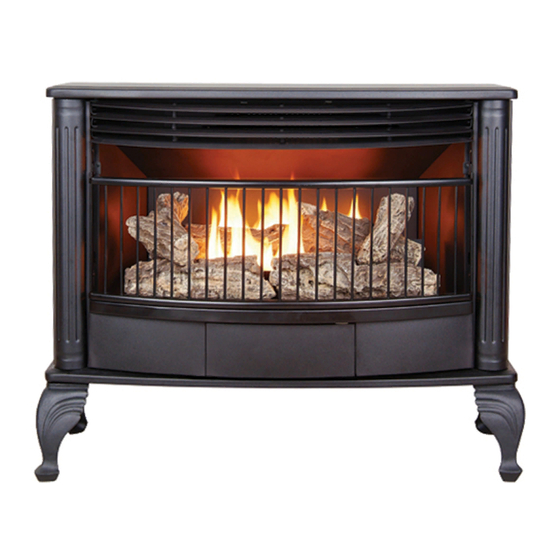
VENT-FREE GAS STOVE
MODEL # QD250T
WARNING: IF THE INFORMATION IN THIS MANUAL IS NOT FOLLOWED
EXACTLY, A FIRE MAY RESULT CAUSING PROPERTY DAMAGE, PERSONAL
INJURY, OR LOSS OF LIFE.
– Do not store or use gasoline or other flammable vapors and liquids in vicinity of
this or any other appliance.
WHAT TO DO IF YOU SMELL GAS
· Do not try to light any appliance.
· Do not touch any electrical switch; do not use any phone in your building.
· Immediately call your gas supplier from a neighbor's phone. Follow the gas
supplier's instructions.
· If you cannot reach your gas supplier, call the fire department.
– Installation and service must be performed by a qualified installer, service agency
or the gas supplier.
This is an unvented gas-fired heater. It uses air (oxygen) from the room in which it is
installed. Provisions for adequate combustion and ventilation air must be provided.
Refer to Air for Combustion and Ventilation section on page 7 of this manual.
INSTALLER: DO NOT DISCARD THIS MANUAL – LEAVE FOR HOMEOWNER'S
FUTURE REFERENCE.
This appliance may be installed in an aftermarket, permanently located manufactured
(mobile) home, where not prohibited by local codes. This appliance is for use with the
type of gas indicated on the rating plate only. This appliance is not convertible for use
with other gases.
Questions about installation, operation, or troubleshooting? Before returning to your retailer, contact our
customer service department at 1-877-886-5989, 8:00 a.m.- 4:30p.m., EST, Monday-Friday or e-mail
customerservice@usaprocom.com
CAUTION – FOR YOUR SAFETY
WARNING: This appliance is
equipped for (Natural and Propane)
gas. Field conversion is not permitted
other than between natural or
propane gases.
PC-QD250T-0805
Advertisement
Table of Contents

Related Manuals for Procom QD250T


Summary of Contents for Procom QD250T
- Page 1 Field conversion is not permitted other than between natural or propane gases. VENT-FREE GAS STOVE MODEL # QD250T CAUTION – FOR YOUR SAFETY WARNING: IF THE INFORMATION IN THIS MANUAL IS NOT FOLLOWED EXACTLY, A FIRE MAY RESULT CAUSING PROPERTY DAMAGE, PERSONAL INJURY, OR LOSS OF LIFE.
-
Page 2: Table Of Contents
WARNING: READ THE INSTALLATION & OPERATION INSTRUCTIONS BEFORE USING THIS APPLIANCE. IMPORTANT: Read instructions and warnings carefully before starting installation. Failure to follow these instructions may result in a possible fire hazard and will void the warranty. PRODUCT SPECIFICATIONS MODEL QD250T Input Rating 25,000 BTU/Hr 25,000 BTU/Hr Gas Type... -
Page 3: Important Safety Information
IMPORTANT SAFETY INFORMATION IMPORTANT: Read this owner’s manual carefully and completely before trying to assemble, operate, or service this heater. Improper use of this heater can cause serious injury or death from burns, fire, explosion, electrical shock, and carbon monoxide poisoning. Only a qualified installer, service agent, or local gas supplier may install and service this product. - Page 4 Always run heater with control knob at PILOT/IGN, LOW or HIGH locked positions. Never set control knob between locked positions. Poor combustion and higher levels of carbon monoxide may result. Do not use heater if any part has been under water. Immediately call a qualified service technician to inspect the room heater and to replace any part of the control system and any gas control which has been under water.
-
Page 5: Product Features
PRODUCT FEATURES SAFETY PILOT This heater has a pilot with an Oxygen Depletion Sensing (ODS) safety shutoff system. ODS/pilot shuts off the heater if there is not enough fresh air. PIEZO IGNITION SYSTEM This heater is equipped with an electronic piezo control system. This system requires AAA batteries (provided). THERMOSTAT HEAT CONTROL The control automatically cycles the burner on and off to maintain a desired room temperature. - Page 6 UNPACKING PRODUCT IDENTIFICATION 1. Remove top inner pack 2. Tilt carton so that heater is upright. 3. Remove protective side packaging. 4. Slide heater out of carton. 5. Remove protective plastic wrap. 6. Hold the screen lift and pull forward. 7.
-
Page 7: Air For Combustion And Ventilation
AIR FOR COMBUSTION AND VENTILATION WARNING: This heater should not be installed in a confined space or unusually tight construction unless provisions are provided for adequate combustion and ventilation air. Read the following instructions to insure proper fresh air for this and other fuel-burning appliances in your home. PRODUCING ADEQUATE VENTILATION This heater shall not be installed in a room or space unless the required volume of indoor combustion air is provided by the method described in the NATIONAL FUEL GAS CODE, ANSI Z223.1/NFPA 54, the INTERNATIONAL FUEL... - Page 8 DETERMINING FRESH-AIR FLOW FOR HEATER LOCATION Determining if You Have a Confined or Unconfined Space Use this worksheet to determine if you have a confined or unconfined space. Space: Includes the room in which you will install heater plus any adjoining rooms with doorless passageways or ventilation grills between the rooms.
- Page 9 Ventilation Air from Inside Building This fresh air would come from adjoining unconfined space. When ventilating to an adjoining unconfined space, you must provide two permanent openings: one within 12 inches of the wall connecting the two spaces ( see options 1 and 2, Figure 2).
-
Page 10: Installation
INSTALLATION NOTICE: This heater is intended for use as supplemental heat. Use this heater along with your primary heating system. Do not install this heater as your primary heat source. If you have a central heating system, you may run system’s circulating blower while using heater. -
Page 11: Connecting To Gas Supply
CONNECTING TO GAS SUPPLY WARNING: A qualified technician must connect heater to gas supply. Follow all local codes. WARNING: This appliance requires a 3/8 in. NPT inlet connection to pressure regulator (see Figure 5). CAUTION: Never connect heater directly to the gas supply. This heater requires an external regulator (not supplied). The external regulator between the gas supply and heater must be installed. - Page 12 CAUTION: Use only new black iron or steel pipe. Internally tinned copper tubing may be used in certain areas. Check your local codes. Use pipe of ½ inch diameter or greater to allow proper volume gas to heater. If pipe is too small, loss of pressure will occur.
- Page 13 For changing from natural gas supply to propane supply 1. Remove bottom screw from cover plate, see figure 8, and rotate to expose gas selection valve. 2. For PROPANE GAS, press in knob using a flat screwdriver with a blade the width of a quarter and turn knob counterclockwise until the knob locks into the LP position (see Figure 10).
-
Page 14: Checking Gas Connections
CHECKING GAS CONNECTIONS WARNING: Test all gas piping and connections for leaks after installing or servicing. Correct all leaks immediately. WARNING: Never use an open flame to check for a leak. Apply a mixture of liquid soap and water to all joints. Bubbles forming show a leak. - Page 15 INSTALLATION Continued INSTALLING LOGS WARNING: Failure to position the parts in accordance with these diagrams or failure to use only parts included may result in property damage or personal injury. CAUTION: After installation, and periodically thereafter, check to ensure that no flame comes in contact with any log.
-
Page 16: Operation
OPERATION FOR YOUR SAFETY READ BEFORE LIGHTING WARNING: If you do not follow these instructions exactly, a fire or explosion may result causing property damage, personal injury or loss of life. NOTICE: During initial operation of new heater, burning logs will give off a paper burning smell. Orange flame will also be present. -
Page 17: Lighting Instructions
LIGHTING INSTRUCTIONS Unscrew ignitor cap and install a AAA battery with the + pointing out. Replace cap. STOP! Read the safety information on page 16. Warning: You must operate this heater with the screen in place. Make sure screen is installed before running heater. Turn control knob clockwise to the OFF position, see Figure 14. - Page 18 TO TURN OFF GAS TO APPLIANCE Shut off heater Turn Control Knob clockwise to the OFF position. Do not force. MANUAL LIGHTING PROCEDURE (Match light) 1. Remove screen by lifting and pulling forward. 2. Follow steps 1 through 5 under Lighting Instructions. 3.
-
Page 19: Inspecting Burners
INSPECTING BURNERS Check pilot flame pattern and burner flame patterns often. PILOT FLAME PATTERN 1. Turn control knob to pilot position 2. Inspect pilot flame and refer to Figure 15 and 16. · Figure 15 shows a correct pilot flame pattern. ·... -
Page 20: Care & Maintenance
CARE AND MAINTENANCE WARNING: Failure to keep primary air openings of burners clean may result in sooting and property damage. CAUTION: You must keep control areas, burner, and circulating air passageways of heater clean. Inspect these areas of heater before each use. Have heater inspected yearly by a qualified service person. Heater may need more frequent cleaning due to excessive lint from carpeting, bedding material, pet hair, etc. -
Page 21: Troubleshooting
TROUBLESHOOTING WARNING: If you smell gas · Shut off gas supply. · Do not try to light any appliance. · Do not touch any electrical switch; do not use any phone in your building. · Immediately call your gas supplier from a neighbor’s phone. Follow the gas supplier’s instructions. ·... - Page 22 OBSERVED PROBLEM PROBABLE CAUSE REMEDY Control knob is not fully pressed Press in control knob fully. ODS/pilot lights but flame goes out when control knob Control knob is not pressed in long After ODS/pilot lights, keep control is released. enough. knob pressed in 30 seconds.
- Page 23 OBSERVED PROBLEM PROBABLE CAUSE REMEDY Slight smoke or odor during 1. Residues from manufacturing 1. Problem will stop after a few hours of initial operation process. operation. Heater produces a whistling 1. Turning control knob to high (5) 1. Turn control knob to low (1) position and noise when burner is lit.
-
Page 24: Replacement Parts
REPLACEMENT PARTS NOTE: Use only original replacement parts. This will protect your warranty coverage for parts replaced under warranty. PARTS UNDER WARRANTY Contact authorized dealers of this product. If they can’t supply original replacement parts, call Customer Service toll free at (1-877-886-5989) for referral information. When calling Customer Service or your dealer, have ready: ·... -
Page 25: Parts List
PARTS LIST This list contains replaceable parts used in your heater. When ordering parts, follow the instructions listed under Replacement Parts on page 24 of this manual. Key No. Part Number Description SIT545-200 T-Stat Valve RV83FI–4/9 Regulator FBB28D01-B Burner Assembly NDD0308 x 400 QD250T007 ODS Outlet Tube... - Page 26 PARTS LIST This list contains replaceable parts used in your heater. When ordering parts, follow the instructions listed under Replacement Parts on 24 of this manual. Key No. Part Number Description BL016-07 Blower Access Panel SL005-01A Blower Bracket QL012-01B Top Panel QL002-01B Top Louver QL014-01A...
- Page 27 Printed in China...
Need help?
Do you have a question about the QD250T and is the answer not in the manual?
Questions and answers