Procom PCNSD25TA Owner's Operation And Installation Manual

Procom PCNSD25TA Owner's Operation And Installation Manual

Vent-free gas stove

Advertisement

WARNING: If the information in this manual is not
followed exactly, a fire or explosion may result causing
property damage, personal injury or loss of life.
— Do not store or use gasoline or other flammable va-
pors and liquids in the vicinity of this or any other
appliance.
— WHAT TO DO IF YOU SMELL GAS
• Do not try to light any appliance.
• Do not touch any electrical switch; do not use any
phone in your building.
• Immediately call your gas supplier from a neighbor's
phone. Follow the gas supplier's instructions.
• If you cannot reach your gas supplier, call the fire
department.
— Installation and service must be performed by a quali-
fied installer, service agency or the gas supplier.
WARNING: This appliance is equipped for Natural and
Propane gas. Field conversion is not permitted other than
between natural or propane gases.
Questions, problems, missing parts? Before returning to your retailer, call
our customer service department at 1-866-573-0674, 7:30 am - 4:15 pm CST,
Monday through Friday or email customerservice@usaprocom.com
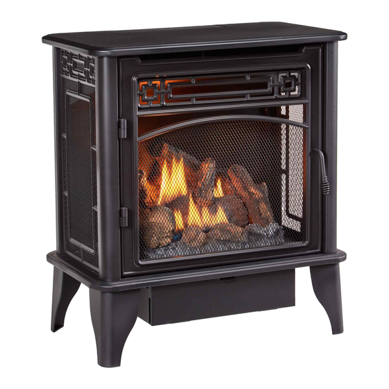
VENT-FREE GAS STOVE
OWNER'S OPERATION
AND INSTALLATION
MANUAL
MODELS
PCNSD25TA
PCNSD25RTA
PFS
®
US

Advertisement

Table of Contents
loading
Need help?

Need help?

Do you have a question about the PCNSD25TA and is the answer not in the manual?

Questions and answers

Summary of Contents for Procom PCNSD25TA

  • Page 1 VENT-FREE GAS STOVE OWNER’S OPERATION AND INSTALLATION MANUAL MODELS PCNSD25TA PCNSD25RTA ® WARNING: If the information in this manual is not followed exactly, a fire or explosion may result causing property damage, personal injury or loss of life. — Do not store or use gasoline or other flammable va- pors and liquids in the vicinity of this or any other appliance.
  • Page 2: Table Of Contents

    * Aftermarket: Completion of sale, not for purpose of resale, from the manufacturer. PROCOM HEATING, INC. PATENT INFORMATION This product may be covered by one or more of the following United States patents:...
  • Page 3: Safety

    SAFETY IMPORTANT: Read this owner’s WARNING: Any change to manual carefully and completely this heater or its controls can before trying to assemble, op- be dangerous. erate, or service this heater. Improper use of this heater can WARNING: Do not allow fans cause serious injury or death to blow directly into fireplace.
  • Page 4: Qualified Installing Agency

    SAFETY 1. Do not place Propane/LP supply tank(s) service technician to inspect the room inside any structure. Propane/LP supply heater and to replace any part of the tank(s) must be placed outdoors. control system and any gas control which has been under water. 2.
  • Page 5: Specifications

    SAFETY PILOT THERMOSTATIC CONTROL This heater has a pilot with an Oxygen Deple- Model PCNSD25TA The control automati- tion Sensing (ODS) safety shutoff system. The cally cycles the burner on and off to maintain ODS/pilot shuts off the heater if there is not a desired room temperature.
  • Page 6: Product Identification

    PRODUCT IDENTIFICATION Screen Logs Heater Controls (Inside Panel) Figure 1 - Vent-Free Stove UNPACKING 1. Remove top inner pack. 6. Hold the screen, lift, and pull forward. 2. Tilt carton so that heater is upright. 7. Remove log set by cutting plastic ties. 3.
  • Page 7: Air For Combustion And Ventilation

    AIR FOR COMBUSTION AND VENTILATION WARNING: This heater shall WARNING: This heater shall not be installed in a room or not be installed in a confined space unless the required vol- space or unusually tight con- ume of indoor combustion air struction unless provisions are is provided by the method de- provided for adequate combus-...
  • Page 8 AIR FOR COMBUSTION AND VENTILATION VENTILATION AIR Ventilation Air From Inside Building This fresh air would come from an adjoining unconfined space. When ventilating to an 12" adjoining unconfined space, you must provide two permanent openings: one within 12" of the Ventilation ceiling and one within 12"...
  • Page 9: Installation

    INSTALLATION CHECK GAS TYPE NOTICE: This heater is intended Be sure your gas supply is right for your heat- for use as supplemental heat. er. Otherwise, call dealer where you bought Use this heater along with your the heater for proper type heater. primary heating system.
  • Page 10 INSTALLATION GAS SELECTION Back of Stove This appliance is factory preset for propane/LP gas. Gas Inlet No changes are required for Gas esté connecting to propane/LP. INLET GAS PRESSURE Only a qualified installer or service MAX 1/2 PSIG (3.5KPa) technician can perform gas selec- Gas Connection tion and connecting to gas supply.
  • Page 11 INSTALLATION 2. Apply thread sealant to the threads on a Use only the cap supplied on the 3/8" NPT brass connection fitting. While regulator. Do not use an off the pushing in, rotate the fitting clockwise until shelf pipe plug. This can damage the threads engage the regulator.
  • Page 12 INSTALLATION CONNECTING TO GAS SUPPLY WARNING: A qualified ser- CAUTION: For natural gas, vice technician must connect check your gas line pressure heater to gas supply. Follow all before connecting heater to gas local codes. line. Gas line pressure must be no greater than 9.5"...
  • Page 13 Field conversion by any other means including the use of a kit is not permitted. Procom Heating, Inc. U.S. Patent Information external regulator with the vent pointing down This product may be covered by one or more of the following United States patents:...
  • Page 14 INSTALLATION CHECKING GAS CONNECTIONS WARNING: Never use an open WARNING: Test all gas piping flame to check for a leak. Apply and connections for leaks after a noncorrosive leak detection installing or servicing. Correct fluid to all joints. If bubbles form, all leaks at once.
  • Page 15 INSTALLATION PRESSURE TESTING HEATER GAS CONNECTIONS 1. Open equipment shutoff valve (see Figure 12, page 14). Apply a noncorrosive leak 10, page 14). detection fluid to all joints. Bubbles form- ing show a leak. 2. Open main gas valve located on or near gas meter for natural gas or open pro- 5.
  • Page 16 INSTALLATION 4. Place pins on log #4 into holes to the left 7. Place log #6 into cutouts in log #1 and log of the burner as shown in Figure 13, page #2 as shown in Figure 16. 15, and Figure 15. 8.
  • Page 17: Operation

    INSTALLATION Ignitor the receiver and remote. Replace all batteries Unscrew ignitor cap and install a AAA battery on a yearly basis or sooner. with the + pointing out. Replace cap. Position the slide switch on the front of the receiver box in the ON position before install- ing batteries.
  • Page 18 OPERATION MODEL PCNSD25TA LIGHTING INSTRUCTIONS for repairs. Until repairs are made, light WARNING: You must operate pilot with match. To light pilot with match, this heater with the door closed see Manual Lighting Procedure, page 19. and in the locked position. Make 7.
  • Page 19 OPERATION THERMOSTAT CONTROL OPERATION The thermostatic control used on this model differs from standard thermostats. Standard ther- mostats simply turn the burner on and off. The thermostat used on this heater senses the room temperature. At times the room may exceed the set temperature. If so, the burner will shut off. The burner will cycle back on when room temperature drops below the set temperature.
  • Page 20 OPERATION • If control knob does not pop up when 9. Turn control knob counterclockwise released, contact a qualified service to the ON position. The main burner technician or gas supplier for repairs. should light. 6. With control knob pressed in, push Note: If burner does not light, push the down and release ignitor button.
  • Page 21 OPERATION REMOTE CONTROL SYSTEM Programming the Remote and Receiver Key Settings The remote and receiver must be “learned” ON - Operates unit to on position, manually to one another. operated solenoid ON. To prepare the receiver box for learning, use OFF - Operates unit to off position, manually a pen or small screwdriver to gently press operated solenoid OFF.
  • Page 22 OPERATION Setting°F/°C Scale 2. Press and hold the SET key until the de- The factory setting for temperature is °F. To sired set temperature is reached. The LCD change this setting to°C, press the ON key screen set numbers will increase from 45° and the OFF key on the remote control at to 99°...
  • Page 23: Inspecting Burners

    INSPECTING BURNERS IMPORTANT: Owner’s should check pilot flame pattern and burner flame pattern often. Incorrect flame patterns indicate the need for cleaning (see Care and Maintenance, page 24 or service. WARNING: Only a qualified service person should service and repair heater. This includes maintenance requiring replacement or alteration of components.
  • Page 24: Care And Maintenance

    CARE AND MAINTENANCE WARNING: Turn off heater and let cool before servicing. CAUTION: You must keep control areas, burner, and circulating air passageways of heater clean. Inspect these areas of heater before each use. Have heater inspected yearly by a qualified service techni- cian.
  • Page 25: Troubleshooting

    CARE AND MAINTENANCE ODS/PILOT Ignitor Use a vacuum cleaner, pressurized air, or a Natural Gas Thermocouple Electrode small, soft bristled brush to clean. Burner Propane/LP A yellow tip on the pilot flame indicates dust Gas Burner and dirt in the pilot assembly. There is a small pilot air inlet hole about 2"...
  • Page 26 TROUBLESHOOTING Problem Possible Cause Corrective Action Using natural gas and I n l e t p r e s s u r e e x c e e d s Bypass pressure switch. See pilot will not light. 9.5" WC. instructions below.
  • Page 27 TROUBLESHOOTING Problem Possible Cause Corrective Action When ignitor button is 1. Gas supply is turned off or 1. Turn on gas supply or open pressed in there is a equipment shutoff valve is equipment shutoff valve. spark at ODS/pilot but closed.
  • Page 28 TROUBLESHOOTING Problem Possible Cause Corrective Action Burner backfiring during 1. Burner orifice is clogged or 1. Clean burner orifice (see combustion. damaged. Care and Maintenance, page 24). 2. Burner is damaged. 2. Contact dealer or customer service. 3. Gas regulator is damaged. 3.
  • Page 29 TROUBLESHOOTING Problem Possible Cause Corrective Action Heater produces un- 1. Heater is burning vapors from 1. Ventilate room. Stop using wanted odors. paint, hair spray, glues, etc. odor causing products while See IMPORTANT statement, heater is running. page 25. 2. Gas leak. See Warning State- 2.
  • Page 30: Parts

    PARTS MODELS PCNSD25TA AND PCNSD25RTA TEMP 14-1 P IL 14-6 PCNSD25RT 14-2 14-7 14-5 PCNSD25T 14-8 14-4 14-3 www.usaprocom.com 200199-01B...
  • Page 31 PARTS MODELS PCNSD25TA AND PCNSD25RTA This list contains replaceable parts for your heater. When ordering replacement parts, follow the instructions listed under Replacement Parts on page 32 of this manual. ITEM PCNSD25TA PCNSD25RTA DESCRIPTION 161139-06 161139-06 161338-01 161338-01 Piezo Ignitor...
  • Page 32: Replacement Parts

    1-866-573-0674 for referral information. ACCESSORIES Purchase these heater accessories from your local dealer. If they can not supply these acces- sories, contact ProCom Heating, Inc. at 1-866-573-0674 for information. EQUIPMENT SHUTOFF VALVE For all models. Equipment shutoff valve with 1/8" NPT tap.
  • Page 33: Service Hints

    You may feel your gas pressure is too low. If so, contact your local gas supplier. TECHNICAL SERVICE You may have further questions about installation, operation, or troubleshooting. If so, contact ProCom Heating, Inc. at 1-866-573-0674. When calling, please have your model and serial numbers of your heater ready. www.usaprocom.com...
  • Page 34 NOTES ________________________________________________________________ ________________________________________________________________ ________________________________________________________________ ________________________________________________________________ ________________________________________________________________ ________________________________________________________________ ________________________________________________________________ ________________________________________________________________ ________________________________________________________________ ________________________________________________________________ ________________________________________________________________ ________________________________________________________________ ________________________________________________________________ ________________________________________________________________ ________________________________________________________________ ________________________________________________________________ ________________________________________________________________ ________________________________________________________________ ________________________________________________________________ ________________________________________________________________ ________________________________________________________________ ________________________________________________________________ ________________________________________________________________ ________________________________________________________________ ________________________________________________________________ www.usaprocom.com 200199-01B...
  • Page 35 NOTES ________________________________________________________________ ________________________________________________________________ ________________________________________________________________ ________________________________________________________________ ________________________________________________________________ ________________________________________________________________ ________________________________________________________________ ________________________________________________________________ ________________________________________________________________ ________________________________________________________________ ________________________________________________________________ ________________________________________________________________ ________________________________________________________________ ________________________________________________________________ ________________________________________________________________ ________________________________________________________________ ________________________________________________________________ ________________________________________________________________ ________________________________________________________________ ________________________________________________________________ ________________________________________________________________ ________________________________________________________________ ________________________________________________________________ ________________________________________________________________ ________________________________________________________________ www.usaprocom.com 200199-01B...
  • Page 36: Warranty

    We make no other warranty, expressed or implied. LIMITED WARRANTY ProCom Heating, Inc. warrants this product to be free from defects in materials and components for ONE (1) year from the date of first purchase, provided that the product has been properly installed by a qualified installer in accordance with all local codes and instructions furnished with the unit, operated and main- tained in accordance with all applicable instructions.

This manual is also suitable for:

Pcnsd25rta

Table of Contents