Sign In
Upload
Manuals
Brands
Raritan Manuals
Switch
PARAGON II Series
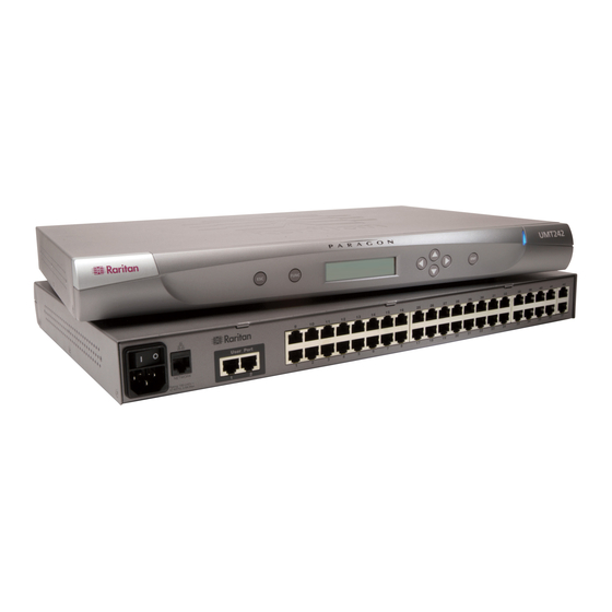
Raritan PARAGON II Series Manuals
Manuals and User Guides for Raritan PARAGON II Series. We have
9
Raritan PARAGON II Series manuals available for free PDF download: User Manual, Quick Installation And Setup Manual, Specifications, Brochure, Quick Manual
Raritan PARAGON II Series User Manual (258 pages)
Brand:
Raritan
| Category:
Switch
| Size: 3 MB
Table of Contents
Table of Contents
4
How-To: Paragon Essentials
11
Case 1. Setting the Network Configuration
11
Case 2. Multiple Write Access to the same Server
12
Case 3. Controlling a Device's Power
12
Case 4. Local Video Redirection (Forced Video)
13
Case 5. Using Multiple Video Ports
14
Case 6. Restoring Settings to Factory Defaults
15
Case 7. Using the Integrated Card Reader
16
Case 8. Creating Multiple Paths to the same Server(S)
17
Case 9. Upgrading the Firmware of Paragon Switches
19
Case 10. Upgrading the Firmware of User Stations
20
Chapter 1 Introduction
23
Paragon II Overview
23
Main Units
25
Cims
25
User Stations
27
Product Photos
27
Product Features
29
Package Contents
31
Chapter 2 Quick Start
33
Basic Installation
33
Step (A): Connect Stacking Units
33
Step (B): Connect User Stations
35
Step (C): Connect Servers
36
Initial Verification
37
Chapter 3 Rackmount and Installation
39
Rack-Mounting
39
Forward Mount
39
Rear Mount
40
A KVM System with a Single Paragon Switch
41
A KVM System with Cascaded Paragon Switches
46
Guideline for Turning on a Cascaded System
51
Installing a P2-UMT832S Stacking Unit
51
Installing a P2-UMT1664S Stacking Unit
52
Note for Turning off the Stacking Unit
53
Installation of the Hubpac
53
Installing a Hubpac
54
Channel Configuration
57
Using the OSUI for Initial Configuration
58
Chapter 4 Front Panel Display and Controls
60
Introduction to Front Panel Components
60
Start-Up Display
60
Normal Display
61
Power up Option
61
Function Selection Screen
62
Selecting a Function
62
Display Ver./Sn
62
Test User UST1
63
Test Chan. UKVM
63
Stacking Support
63
Test Stack Unit
64
Set LCD Contrast
64
Re-Configure
64
Set IP Address
64
Reset Unit
65
Chapter 5 Information about Keyboard, Mouse and Video
67
Support for Widescreen LCD Monitors
67
Connecting the DDC2 Adapter
67
Compatible USB Combination Keyboards
69
How to Connect a USB Combo Keyboard
69
Replacing or Reconnecting the USB Mouse
70
Changing the Keyboard Layout Settings
70
USB Keyboard Layout Settings (P2CIM-AUSB, P2CIM-AUSB-B or P2ZCIM-USB)
71
Sun Keyboard Layout Settings (P2CIM-SUN or P2CIM-ASUN)
73
Sun Keyboard Layout Settings (P2ZCIM-SUN)
74
Switching between 101 and 102 Keys (P2CIM-APS2)
75
Kensington Mouse Type Settings
75
Emulating Sun Keys with a PS/2 Keyboard
77
Macintosh Key Mapping
78
Chapter 6 Operation - User Functions
79
Login
80
Video Gain and Skew Compensation
82
Video Gain Adjustment
82
Skew Compensation with P2-EUST or P2-EUST/C
83
Selecting a Server
84
Messages Shown in Public View (P-View) Mode
87
Blocked Channels Identification in Private Mode
88
Manually Selecting the Access Path
89
Path Overlapping Constraint
91
Switching between Previous and Next Channels
94
Definition of the Previous and Next Channels
95
Performing the Up/Down Channel Function
95
User Profile Customization
98
User Profile Parameters and How to Change Settings
99
Help Menu
102
Keyboard-Controlled OSUI Functions
102
Information Menu
104
Concurrent Multiple Video Outputs
105
Naming Convention for Multiple Video
106
Connecting Cims to a Multi-Channel Video Server
106
Operation Rules
107
Messages on the ACTIVATOR User Station
108
Messages on the FOLLOWER User Stations
109
Using P2-USTIP for Multiple Video Outputs
109
Authentication with a Smart Card
109
Installing the P2CIM-AUSB-C Driver in Windows
110
Requisites for Card Reader Functionality
113
Using the Card Reader
116
In this Chapter the Administration Menu
119
Guidelines for System Configuration
120
System Configuration
121
Video Redirection (Forced Video)
125
Operating Forced Video Using OSUI
126
Operating Forced Video Using Paragon Manager
127
User Station Receiving Forced Video
127
Channel Association for Multiple Video
128
Channel Association Guidelines
129
User Configuration
129
Channel Configuration
131
Video Display Adjustment for P2-EUST
133
User Station Profile
134
Keyboard Type
134
Video Delay
135
User Port Timeout
136
Group Settings (Access Rights)
136
Recommendations
139
System Reboot and System Reset
139
System Reboot
139
System Reset
140
Network Settings
141
Autoscan and Autoskip
143
Power Management
143
Configuring and Naming the Power Strip
144
Associating a Device with a Power Outlet
145
Controlling Power to an Outlet
146
Paragon II Network Port
147
Chapter 7 Operation - Administrator Functions
119
The Administration Menu
119
Chapter 8 P2Zcims and Z-Cims
148
Introduction
148
P2ZCIM Features
148
Z-Cims Features (for Paragon Release 4.4 or Earlier)
149
Paragon II and P2Zcims
149
Connecting P2Zcims as Tiers
150
P2ZCIM LED Status
154
Paragon II and Z-Cims (for Paragon Release 4.4 or Earlier)
155
Connecting Z-Cims as Tiers
156
Using a UKVMSPD Z-CIM with a Local PC
159
Chapter 9 Managing IBM Bladecenter Servers
161
Refreshing Channel Status
162
Renaming a Bladecenter Chassis
163
Renaming a Blade Server
164
Chapter 10 Configurations
166
Principles of Re-Connection
166
Tiered Configurations
167
Standard Tiered Configurations
167
Common Guidelines for Tiering Configuration
167
Non-Standard Tiered Configurations
170
Stacked Configurations
175
Definition of Stacked Configuration
175
System Constraints
175
Standard Stacked Configurations
176
Loop-Back Configuration
179
P2-Hubpac Configuration and Multiple Video
180
Configuration for Multiple Video
180
Chapter 11 User Station Direct Mode
184
Chapter 12 Firmware Upgrade
186
General Update Procedure
186
STEP (A): Download the Latest Firmware and Release Notes
186
STEP (B): Establish a Connection between the Device and the PC
187
STEP (C): (Optional) Verify the Stacking-Related Configuration
188
STEP (D): Launch the Paragon Update Utility
188
Failsafe Upgrade Feature
189
Main Units
190
Stacking Units
191
User Stations
194
P2-Hubpac Upgrade Operation
195
STEP (A): Get the Latest Firmware, Driver and Release Notes
195
STEP (B): Connect One Cluster of the Hubpac to the PC
196
STEP (C): Install the USB-To-RS485 Driver on the PC
198
STEP (D): Launch the Paragon Update Utility
202
STEP (E): Repeat Steps (B) and (D) for the Other Clusters
203
Appendix A Specifications
204
Specifications of Paragon II Components
204
Cat5 Cable Guidelines
208
Appendix B Tiering and Compatibility
210
Tiering Matrix
210
Compatibility Matrix
212
Double Diamond Configuration
214
Appendix C Recommendation for Better Video Quality
215
Deployment Recommendations
215
Supported Resolutions on P2-EUST and P2-EUST/C
216
Appendix D Connecting Serial Devices to Paragon II System
217
Introduction to Serial Cims
217
Installing a Serial CIM
218
Installing P2CIM-SER or P2CIM-SER-EU
218
Installing AUATC
218
Operating a Serial CIM
220
P2CIM-SER or P2CIM-SER-EU
220
Auatc
221
Configuring AUATC
225
Troubleshooting AUATC
226
Appendix E Other Raritan Components Working with Paragon
228
Paragon Manager Overview
228
Installing Paragon Manager
228
Commandcenter Secure Gateway Integration
228
Remotely Refreshing IBM Bladecenter Channel Status
229
Commandcenter Secure Gateway Integration
229
PCCI Integration
230
Dominion KX II Integration
231
Appendix F Integration with Third-Party Switching Devices
234
Using the Omniview Secure KVM Switch
234
Using the NVISION NV5128 Multi-Format Router
234
Integration with Third-Party Switching Devices
236
Special Notice with the P2-EUST/C Card Reader
236
Supported Keyboards
236
Using the NVISION NV5128 Multi-Format Router
238
Advertisement
Raritan PARAGON II Series User Manual (239 pages)
Brand:
Raritan
| Category:
Switch
| Size: 5 MB
Table of Contents
Table of Contents
4
How-To: Paragon Essentials
10
Case 1. Setting the Network Configuration
10
Case 2. Multiple Write Access to the same Server
11
Case 3. Controlling a Deviceʹs Power
11
Case 4. Local Video Redirection (Forced Video)
12
Case 5. Using Multiple Video Ports
13
Case 6. Restoring Settings to Factory Defaults
14
Case 7. Using the Integrated Card Reader
15
Case 8. Creating Multiple Paths to the same Server(S)
16
Case 9. Upgrading the Firmware of Paragon Switches
18
Case 10. Upgrading the Firmware of User Stations
19
Chapter 1 Introduction
21
Paragon II Overview
21
In this Chapter
21
Product Photos
26
Product Features
28
Package Contents
31
Chapter 2 Installation
32
Basic Installation
32
Initial Administrative Verification
34
Paragon II Front Panel Display and Controls
36
Start-Up Display
36
Normal Display
36
Power up Option
37
Function Selection Screen
37
Selecting a Function
38
Initial Configuration
41
Using the OSUI for Initial Configuration
42
Installing a Paragon System with a Single Matrix Switch
44
Installing a Cascaded Paragon System
49
Rules of Powering on a Cascaded System
54
Installing the Paragon P2-UMT832S Stacking Unit
55
Installing the Paragon P2-UMT1664S Stacking Unit
55
Important Note about Powering off the Stacking Unit
56
Installing a Hubpac
57
Chapter 3 Operation - User Functions
61
Login
62
Video Gain and Skew Compensation
64
Video Gain Adjustment and Skew Compensation in P2-EUST
65
Video Gain Adjustment in P2-UST
66
Selecting a Server
67
Manually Selecting the Access Path
72
Path Overlapping Constraint
74
Switching between Previous and Next Channels
78
Definition of the Previous and Next Channels
79
Performing the Up/Down Channel Function
79
User Profile Customization
82
User Profile Parameters and How to Change Settings
83
Help Menu
86
Keyboard-Controlled OSUI Functions
86
Information Menu
88
Concurrent Multiple Video Outputs
89
Naming Convention for Multiple Video
90
Connecting Cims to a Multi-Channel Video Server
90
Operation Rules
91
Messages on the ACTIVATOR User Station
92
Messages on the FOLLOWER User Stations
93
Using P2-USTIP for Multiple Video Outputs
94
Authentication with a Smart Card
94
Installing the P2CIM-AUSB-C Driver in Windows
94
Requisites for Card Reader Functionality
98
Using the Card Reader
101
Chapter 4 Operation - Administrator Functions
104
The Administration Menu
104
Guidelines for System Configuration
105
System Configuration
106
Video Redirection (Forced Video)
111
Operating Forced Video Using OSUI
112
Operating Forced Video Using Paragon Manager
113
User Station Receiving Forced Video
114
Channel Association for Multiple Video
114
Channel Association Guidelines
115
User Configuration
115
Channel Configuration
117
Video Display Adjustment for P2-EUST
119
User Station Profile
120
Keyboard Type
120
Video Delay
121
User Port Timeout
122
Group Settings (Access Rights)
122
Recommendations
125
System Reboot and System Reset
125
System Reboot
126
System Reset
127
Network Settings
128
Autoscan and Autoskip
130
Power Management
130
Configuring and Naming the Power Strip
131
Associating a Device with a Power Outlet
131
Controlling Power to an Outlet
133
Paragon II Network Port
135
Chapter 5 Paragon II and P2Zcims/Z-Cims
136
Introduction
136
P2Zcims
137
Z-Cims (UKVMSPD and UKVMSC)
137
Paragon II and P2Zcims
138
Connecting P2Zcims as Tiers
138
P2ZCIM LED Status
143
Paragon II and Z-Cims
143
Connecting Z-Cims as Tiers
144
Using a UKVMSPD Z-CIM with a Local PC
147
Chapter 6 Managing IBM Bladecenter Servers
150
Refreshing Channel Status
151
Renaming a Bladecenter Chassis
152
Renaming a Blade Server
153
Chapter 7 Configurations
155
Principles of Re-Connection
155
Tiered Configurations
156
Standard Tiered Configurations
156
Stacked Configurations
159
Standard Stacked Configurations
160
Non-Standard Tiered Configurations
163
Guidelines for Existing Firmware Versions
163
Loop-Back Configuration
168
P2-Hubpac Configuration and Multiple Video
169
Configuration for Multiple Video
169
Chapter 8 Firmware Upgrade
173
General Update Procedure
173
Failsafe Upgrade Feature
176
Main Units
177
Stacking Units
179
User Stations
182
P2-Hubpac Upgrade Operation
183
Appendix A Specifications
192
Specifications of Paragon II Components
192
Cat 5 Cable Guidelines
196
Appendix B User Station Direct Mode
198
Appendix C Tiering and Compatibility
200
Tiering Matrix
200
Compatibility Matrix
202
Double Diamond Configuration
204
Appendix D Paragon II Rack Mount
205
Forward Mount
205
Rear Mount
206
Appendix E Connecting Serial Devices to Paragon II System
208
Introduction to Serial Cims
208
Installing a Serial CIM
209
Installing P2CIM-SER or P2CIM-SER-EU
209
Installing AUATC
209
Operating a Serial CIM
211
P2CIM-SER or P2CIM-SER-EU
211
Auatc
212
Configuring AUATC
217
Troubleshooting AUATC
218
Appendix F Extra Keyboard/Mouse Information and Settings
220
Emulating Sun Keys with a PS/2 Keyboard
220
Changing the Keyboard Layout Settings
221
USB Keyboard Layout Settings (P2CIM-AUSB, P2CIM-AUSB-B or P2ZCIM-USB)
221
Sun Keyboard Layout Settings (P2CIM-SUN or P2CIM-ASUN)
223
Sun Keyboard Layout Settings (P2ZCIM-SUN)
225
Switching between 101 and 102 Keys (P2CIM-APS2)
225
Kensington Mouse Type Settings
226
Macintosh Key Mapping
228
Raritan PARAGON II Series User Manual (152 pages)
Release 4.2
Brand:
Raritan
| Category:
Switch
| Size: 5 MB
Table of Contents
Fcc Information
3
Table of Contents
5
Chapter 1: Introduction
11
Paragon II Overview
11
Figure 1 Overview of a Paragon II Sample System
12
Product Photos
13
Figure 2 Paragon II Main Switching Units
13
Figure 3 P2-UMT832 ( ), P2-UST ( ), and P2CIM-APS2 ( )
13
Figure 4 P2-EUST
13
Product Features
14
Package Contents
16
Chapter 2: Installation
17
Basic Installation
17
Figure 5 Installation Diagram
17
Figure 6 Login Screen
18
Initial Administrative Verification
18
Paragon II Front Panel Display and Controls
19
Figure 7 Selection Menu
19
Figure 8 Paragon II Front Panel Buttons
19
Figure 9 LCD Normal Display
20
Figure 10 Power up Clear Database
20
Figure 11 LCD Functions
21
Figure 12 Function Selection
21
Figure 13 Display Ver. and SN
21
Figure 14 User Station Test
21
Figure 15 Channel CIM (UKVM) Test
22
Figure 16 Stacking Support
22
Figure 17 Set LCD Contrast
22
Figure 18 Auto Configure
22
Figure 19 Data Update Message
23
Initial Configuration
24
Using the OSUI for Initial Configuration
24
Figure 20 Format of OSUI Screens
24
Installing a Paragon System with a Single Matrix Switch
26
Figure 21 Login Screen for Paragon II
26
Figure 22 Selection Menu
27
Figure 23 Administration Menu
28
Figure 24 Channel Configuration Menu of a P2-UMT442
28
Installing a Cascaded Paragon System
29
Figure 25 Sample Cascaded System
29
Figure 26 Selection Menu
30
Figure 27 Administration Menu
31
Figure 28 Channel Configuration Menu for a P2-UMT442
31
Important Note about Powering off the Stacking Unit
33
Installing the Paragon P2-UMT1664S Stacking Unit
33
Installing the Paragon P2-UMT832S Stacking Unit
33
Installing a Hubpac
34
Figure 29 Connecting a P2-UMT1664M to a Hubpac
35
Chapter 3: Operation - User Functions
37
Login
37
Figure 30 Login Menu
37
Figure 31 Selection Menu for a P2-UMT442
38
Video Gain and Skew Compensation
39
Video Gain Adjustment and Skew Compensation in P2-EUST
39
Figure 32 Manual Video Gain/Skew Delay Adjustment Display for P2-EUST
39
Video Gain Adjustment in P2-UST
40
Figure 33 Manual Video Gain Adjustment for P2-UST
40
Selecting a Server
41
Figure 34 Selection Menu in Order by Channel Port Number
41
Figure 35 Selection Menu in Order by Port Name
41
Figure 36 Selection Menu for Manually Selecting the Access Path
44
Manually Selecting the Access Path
44
Figure 37 Selection Menu after Manually Selecting the Access Path
45
Figure 38 On-Screen Path Information
45
Figure 39 Path Overlapping Instance 1
46
Path Overlapping Constraint
46
Figure 40 Path Overlapping Instance 2
47
Figure 41 Path Overlapping Instance 3
47
User Profile Customization
48
Figure 42 Path Overlapping Instance 4
48
Figure 43 User Profile Menu
48
Figure 44 Directional Prompts in Message Bar
49
User Profile Parameters and How to Change Settings
49
Figure 45 Prompt in Message Bar to Save Changes
50
Help Menu
51
Figure 46 Help Menu
51
Keyboard-Controlled OSUI Functions
52
Information Menu
53
Figure 47 Information Menu
53
Concurrent Multiple Video Outputs
54
Figure 48 Illustration of Multiple Video
54
Connecting Cims to a Multi-Channel Video Server
55
Naming Convention for Multiple Video
55
Operation Rules
55
Figure 49 Sample Messages for Multiple Video Output Results
56
Messages on the ACTIVATOR User Station
56
Figure 50 Multiple Video Message on the FOLLOWER User Stations
57
Messages on the FOLLOWER User Stations
57
Using P2-USTIP for Multiple Video Outputs
57
Chapter 4: Operation - Administrator Functions
59
The Administration Menu
59
Figure 51 Administration Menu
59
Guidelines for System Configuration
60
System Configuration
60
Figure 52 System Configuration Menu for P2-EUST
60
Video Redirection (Forced Video)
62
Operating Forced Video Using OSUI
63
Figure 53 Illustration of Forced Video
63
Operating Forced Video Using Paragon Manager
64
Figure 54 Forced Video Switch Message
64
Figure 55 Successful Forced Video Message
64
User Station Receiving Forced Video
65
Figure 56 Paragon Manager Connection to Different Paragon Units
65
Figure 57 Message on the Forced Video User Station
65
Figure 58 Logout Prompt on the User Station Receiving Forced Video
65
Channel Association for Multiple Video
66
Channel Association Guidelines
66
User Configuration
67
Figure 59 Left Panel of the User Configuration Menu
67
Figure 60 Right Panel of the User Configuration Menu
68
Channel Configuration
69
Figure 61 Left Panel of the Channel Configuration Menu
69
Figure 62 Right Panel of the Channel Configuration Menu
70
Figure 63 Selection Menu
71
Figure 64 Selection Menu with RGB Skew Delay Active
71
Video Display Adjustment for P2-EUST
71
User Station Profile
72
Keyboard Type
72
Video Delay
72
Figure 65 User Station Profile Screen
72
Group Settings (Access Rights)
73
Recommendations
74
System Reboot and System Reset
75
System Reboot
75
Figure 66 System Reboot
75
System Reset
76
Figure 67 System/Device Reset Screen
76
Figure 68 Data Update Message
76
Network Settings
77
Figure 69 Network Settings Menu
77
Autoscan and Autoskip
78
Power Management
78
Configuring and Naming the Power Strip
79
Associating a Device with a Power Outlet
79
Controlling Power to an Outlet
79
Paragon II Network Port
80
Chapter 5: Paragon II and P2Zcims/Z-Cims
83
Introduction
83
P2Zcims
83
Z-Cims (UKVMSPD and UKVMSC)
83
Paragon II and P2Zcims
84
Connecting P2Zcims as Tiers
84
Figure 70 Connecting P2Zcims as Tiers to Paragon II
84
Figure 71 Resizing the P2ZCIM Chain
86
Figure 72 Refreshing the P2ZCIM Chain
86
P2ZCIM LED Status
87
Paragon II and Z-Cims
88
Connecting Z-Cims as Tiers
88
Figure 73 Connecting Z-Cims or P2Zcims as Tiers
88
Using a UKVMSPD Z-CIM with a Local PC
90
Figure 74 User Profile Menu
91
Chapter 6: Managing IBM Bladecenter Servers
93
Refreshing Channel Status
93
Figure 75 Refresh IBM Bladecenter Servers
93
Renaming a Bladecenter Chassis
94
Figure 76 IBM Blade Server Status after Refreshing
94
Figure 77 Renaming the Channel of IBM Bladecenter Chassis
94
Renaming a Blade Server
95
Figure 78 Renaming the IBM Blade Server's Channel
95
Chapter 7: Configurations
97
Principles of Re-Connection
97
Tiered Configurations
98
Standard Tiering Configurations
98
Figure 79 Single Base Configuration
99
Stacked Configurations
100
Figure 80 Multiple Base Configuration
100
Figure 81 Stacking - Single Base Configuration with P2-UMT1664M and P2-UMT1664S
102
Figure 82 Stacking - Single Base Configuration with P2-UMT832M and P2-UMT832S
102
Figure 83 Stacking - Single Base Configuration with P2-UMT1664M and P2-UMT1664S
102
Standard Stacking Configurations
102
Figure 84 Stacking - Single Base Configuration with P2-UMT832M and P2-UMT832S
103
Figure 85 ILLEGAL Stacking - Single Base Configuration with P2-UMT1664M and P2-UMT832S
103
Figure 86 ILLEGAL Stacking - Single Base Configuration with P2-UMT1664M and P2-UMT1664S
104
Figure 87 ILLEGAL Stacking - Single Base Configuration with P2-UMT1664M and P2-UMT832S
104
Figure 88 ILLEGAL Stacking - Single Base Configuration with P2-UMT1664M and Two P2-UMT1664S
104
Non-Standard Tier Configuration
105
Guidelines for Existing Firmware Versions
105
Figure 89 Triangle Configuration
105
Figure 90 Single Diamond Configuration
106
Figure 91 Double Diamond Configuration
106
Figure 92 Redundant Configuration
107
Loop-Back Configuration
108
Figure 93 Recommended Redundant Configuration Connection Scheme
108
Figure 94 Illegal Loop-Back Configuration
108
Chapter 8: Firmware Upgrade
109
General Update Procedure
109
Failsafe Upgrade Feature
110
Main Switching Units
110
Figure 95 Main Switching Unit -- Boot Loader Successfully Upgraded
111
Figure 96 Boot Loader Mode of Main Switching Unit
111
Stacking Units
112
User Stations
113
Figure 97 Boot Loader Modes of Stacking Unit
113
Appendix A: Specifications
115
CAT5 Cable Guidelines
117
Figure 98 Cat5 Cable Diagram
117
Appendix B: User Station Direct Mode
119
Appendix C: Tiering and Compatibility
121
Tiering Matrix
121
Compatibility Matrix
122
Double Diamond Configuration
123
Figure 99 Double Diamond Configuration
123
Appendix D: Paragon II Rack Mount
125
Forward Mount
125
Figure 100 Front Rackmount of a P2 Matrix Switch
125
Figure 101 Front Rackmount of a P2 Matrix Switch
125
Rear Mount
126
Figure 102 Rear Rackmount of a P2 Matrix Switch
126
Figure 103 Rear Rackmount of a P2 Matrix Switch
126
Appendix E: Connecting Serial Devices to Paragon II System
127
Introduction to Serial Cims
127
Installing a Serial CIM
127
Installing P2CIM-SER or P2CIM-SER-EU
127
Installing AUATC
127
Operating a Serial CIM
128
P2CIM-SER or P2CIM-SER-EU
128
Auatc
128
Figure 104 AUATC Screen Layout (on Line Mode)
129
Figure 105 Help Screen
131
Figure 106 Buffer Edit Mode Screen
132
Configuring AUATC
133
Figure 107 Setup Communication Screen
133
Figure 108 Set up Programmable Keys Screen
134
Troubleshooting AUATC
135
Advertisement
Raritan PARAGON II Series User Manual (112 pages)
Brand:
Raritan
| Category:
Switch
| Size: 1 MB
Table of Contents
Fcc Information
3
Japanese Approvals
3
Safety Guidelines
4
Table of Contents
5
Chapter 1: Introduction
9
Paragon II Overview
9
Product Photos
10
Figure 1 Paragon II Base Units
10
Figure 2 P2-UMT832, P2-UST, and P2CIM-PS2
10
Figure 3 P2-EUST
10
Product Features
11
Package Contents
12
Chapter 2: Installation
13
Basic Installation
13
Figure 4 Installation Diagram
13
Figure 5 Login Menu
14
Initial Administrative Testing
14
Paragon II Front Panel Display and Controls
15
Figure 6 Selection Menu
15
Figure 7 Paragon II Front Panel Buttons
15
Figure 8 LCD Normal Display
16
Figure 9 Power up Clear Database
16
Figure 10 LCD Functions
17
Figure 11 Function Selection
17
Figure 12 Display Ver. and SN
17
Figure 13 User Station Test
17
Figure 14 Channel CIM (UKVM) Test
18
Figure 15 Stacking Support
18
Figure 16 Set LCD Contrast
18
Figure 17 Auto Configure
18
Initial Configuration
20
Using the OSUI for Initial Configuration
20
Figure 18 Format of OSUI Screens
20
Installing a Paragon System with a Single Base Unit
21
Figure 19 Login Menu for a P2-UMT832M
21
Figure 20 Selection Menu for a P2-UMT832M
22
Figure 21 Administration Menu
23
Figure 22 Channel Configuration Menu of a P2-UMT832M
24
Installing a Cascaded Paragon System
25
Figure 23 Sample Cascaded System
25
Figure 24 Selection Menu
26
Figure 25 Administration Menu
27
Figure 26 Channel Configuration Menu for a P2-UMT832M
27
Installing the Paragon P2-UMT1664S Stacking Unit
29
Installing the Paragon P2-UMT832S Stacking Unit
29
Figure 27 Paragon Hubpac
30
Installing a Hubpac
30
Figure 28 Connecting a P2-UMT832M to a Hubpac
31
Chapter 3: Operation - User Functions
33
Login
33
Figure 29 Login Menu for a P2-UMT832M
33
Figure 30 Selection Menu for a P2-UMT832M
34
Manual Video Gain and Skew Compensation in P2-EUST
35
Figure 31 Manual Video Gain/Skew Delay Adjustment Display for P2-EUST
35
Figure 32 Manual Video Gain Adjustment for P2-UST
36
Video Gain Adjustment in P2-UST
36
Selecting a Server
37
Figure 33 Selection Menu in Order by Channel Port Number
37
Figure 34 Selection Menu in Order by Port Name
37
User Profile Customization
41
Figure 35 User Profile Menu
41
User Profile Parameters and How to Change Settings
42
Help Menu
43
Figure 36 Help Menu
43
Keyboard-Controlled OSUI Functions
44
Information Menu
45
Figure 37 Information Menu
45
Chapter 4: Operation - Administrator Functions
47
The Administration Menu
47
Figure 38 Administration Menu
47
Guidelines for System Configuration
48
System Configuration
48
Figure 39 System Configuration Menu for P2-EUST
48
User Configuration
51
Figure 40 Left Panel of the User Configuration Menu
51
Figure 41 Right Panel of the User Configuration Menu
52
Channel Configuration
53
Figure 42 Left Panel of the Channel Configuration Menu
53
Figure 43 Right Panel of the Channel Configuration Menu
54
Figure 44 Selection Menu
55
Figure 45 Selection Menu with RGB Skew Delay Active
55
Video Display Adjustment for P2-EUST
55
User Station Profile
57
Keyboard Type
57
Video Delay
57
Figure 46 User Station Profile Screen
57
Group Settings (Access Rights)
58
Recommendations
59
Network Settings
60
Figure 47 Network Settings Menu
60
Autoscan and Autoskip
61
Power Management
61
Configuring and Naming the Power Strip
61
Associating a Target with a Power Outlet
62
Controlling Power to an Outlet
62
Paragon II Network Port
63
Chapter 5: Paragon II and Z-Cims
65
Introduction
65
UKVMSPD (and UKVMSC) Z-Cims
65
P2Zcims
66
Figure 48 Close-Up of CIM Chain between Servers
66
Paragon II and UKVMSPD Z-Cims
67
Using a UKVMSPD with a Local PC
67
Figure 49 User Profile Menu
67
Connecting Z-Cims and P2Zcims as Tiers
68
Figure 50 Connecting Z-Cims or P2Zcims as Tiers
68
Resize or Refresh a P2ZCIM Chain
71
P2Zcims
71
Connecting P2Zcims as Tiers
71
Figure 51 Connecting P2Zcims as Tiers to Paragon II
71
Figure 52 Resize the P2ZCIM Chain
73
Figure 53 Refresh the P2ZCIM Chain
73
P2ZCIM LED Status
74
Figure 54 Refresh the P2ZCIM Chain
74
Chapter 6: Configurations
75
Principles of Re-Connection
75
Tiered Configurations
76
Standard Tiering Configurations
76
Figure 55 Single Base Configuration
76
Figure 56 Multiple Base Configuration
77
Stacked Configurations
78
Standard Stacking Configurations
79
Figure 57 Stacking - Single Base Configuration with P2-UMT1664M and P2-UMT1664S
79
Figure 58 Stacking - Single Base Configuration with P2-UMT832M and P2-UMT832S
79
Figure 59 Stacking - Single Base Configuration with P2-UMT1664M and P2-UMT1664S
79
Figure 60 Stacking - Single Base Configuration with P2-UMT832M and P2-UMT832S
80
Figure 61 Stacking - Single Base Configuration with P2-UMT1664M and P2-UMT832S
80
Figure 62 Illegal Stacking - Single Base Configuration with P2-UMT832M and P2-UMT1664S
81
Figure 63 Illegal Stacking - Single Base Configuration with P2-UMT1664M and P2-UMT832S
81
Figure 64 Illegal Stacking - Single Base Configuration with P2-UMT1664M and Two P2-UMT1664S
81
Non-Standard Tier Configuration
82
Guidelines for Existing Firmware Versions
82
Figure 65 Triangle Configuration
82
Figure 66 Diamond Configuration
83
Figure 67 Redundant Configuration
84
Illegal Configuration
85
Loop-Back Configuration
85
Figure 68 Recommended Redundant Configuration Connection Scheme
85
Figure 69 Illegal Loop-Back Configuration
85
Appendix A: Specifications
87
CAT5 Cable Guidelines
88
Figure 70 Cat5 Cable Diagram
88
Appendix B: User Station Direct Mode
89
Appendix C: Tiering and Compatibility
91
Tiering Matrix
91
Compatibility Matrix
92
Appendix D: Paragon II Rack Mount
93
Forward Mount
93
Figure 71 Front Rackmount of a P2 Base Unit
93
Figure 72 Front Rackmount of a P2 User Station
93
Rear Mount
94
Figure 73 Rear Rackmount of a P2 Base Unit
94
Figure 74 Rear Rackmount of a P2 User Station
94
Raritan PARAGON II Series User Manual (96 pages)
Raritan Computer Paragon II Network Device User Manual
Brand:
Raritan
| Category:
Switch
| Size: 2 MB
Table of Contents
Fcc Information
5
Japanese Approvals
5
Table of Contents
7
Chapter 1: Introduction
11
Paragon II Overview
11
Product Photos
12
Figure 1 Paragon II Base Units
12
Figure 2 P2-UMT832, P2-UST, and P2CIM-PS2
12
Product Features
13
Package Contents
14
Chapter 2: Installation
15
Basic Installation
15
Figure 3 Installation Diagram
16
Initial Administrative Testing
17
Figure 4 Login Menu
17
Figure 5 Selection Menu
17
Paragon II Front Panel Display and Controls
18
Figure 6 Paragon II Front Panel Buttons
18
Figure 7 LCD Normal Display
19
Figure 8 Power up Clear Database
19
Figure 9 LCD Functions
19
Figure 10 Function Selection
19
Figure 11 Display Ver. and SN
20
Figure 12 User Station Test
20
Figure 13 Channel CIM (UKVM) Test
20
Figure 14 Stacking Support
20
Figure 15 Set LCD Contrast
20
Figure 16 Auto Configure
21
Initial Configuration
22
Using the OSUI for Initial Configuration
22
Figure 17 Format of OSUI Screens
22
Installing a Paragon System with a Single Base Unit
23
Figure 18 Rear Panel of a Paragon User Station and P2-UMT832M Unit
23
Figure 19 Login Menu for a P2-UMT832M
24
Figure 20 Selection Menu for a P2-UMT832M
24
Figure 21 Administration Menu
25
Figure 22 Channel Configuration Menu of a P2-UMT832M
26
Installing a Cascaded Paragon System
27
Figure 23 Sample Cascaded System
27
Figure 24 Selection Menu
28
Figure 25 Administration Menu
28
Figure 26 Channel Configuration Menu for a P2-UMT832M
29
Installing a Paragon Stacking Switch
30
Chapter 3: Operation - User Functions
31
Login
31
Figure 27 Login Menu for a P2-UMT832M
31
Figure 28 Selection Menu for a P2-UMT832M
32
Selecting a Server
33
Figure 29 Selection Menu in Order by Channel Port Number
33
Figure 30 Selection Menu in Order by Name
34
User Customization
36
Figure 31 User Profile Menu
36
User Profile Parameters and How to Change Settings
37
Help Menu
38
Figure 32 Help Menu
38
Keyboard-Controlled OSUI Functions
39
Information Menu
40
Figure 33 Information Menu
40
Chapter 4: Operation - Administrator Functions
41
The Administration Menu
41
Figure 34 Administration Menu
41
Guidelines for System Configuration
42
System Configuration
42
Figure 35 System Configuration Menu
42
User Configuration
44
Figure 36 the "Left End" of the User Configuration Menu
44
Figure 37 the "Right End" of the User Configuration Menu
45
Channel Configuration
46
Figure 38 the "Left End" of the Channel Configuration Menu
46
Figure 39 the "Right End" of the Channel Configuration Menu
47
User Station Profile
48
Keyboard Type
48
Video Delay
48
Figure 40 User Station Profile Screen
48
Group Settings (Access Rights)
49
Recommendations
50
Network Settings
51
Figure 41 Network Settings Menu
51
Autoscanning and Autoskipping
52
Power Management
53
Configuring and Naming the Power Strip
53
Associating a Target with a Power Outlet
53
Controlling Power to an Outlet
54
Paragon II Network Port
54
Chapter 5: Paragon II and Z-CIM
55
Connecting Z-Cims as Tiers
56
Figure 42 Connecting a Z-CIM as a Tier to Paragon II
56
Chapter 6: IBM X330
59
Figure 43 IBM X330 Tiered from a Paragon II Matrix Switch
59
Chapter 7: Configurations
61
Principles of Re-Connection
61
Tiered Configurations
62
Standard Tiering Configurations
62
Figure 44 Single Base Configuration
62
Figure 45 Multiple Base Configuration
63
Stacked Configurations
64
Standard Stacking Configurations
65
Single Base with Stacking
65
Figure 46 Stacking - Single Base Configuration with P2-UMT1664M and P2-UMT1664S
65
Figure 47 Stacking - Single Base Configuration with P2-UMT832M and P2-UMT832S
65
Figure 48 Stacking - Single Base Configuration with P2-UMT832M and P2-UMT832S
65
Figure 49 Stacking - Single Base Configuration with P2-UMT832M and P2-UMT832S
66
Figure 50 Stacking - Single Base Configuration with P2-UMT1664M and P2-UMT832S
66
Figure 51 Stacking - Single Base Configuration with P2-UMT832M and P2-UMT1664S
66
Figure 52 Stacking - Single Base Configuration with P2-UMT1664M and P2-UMT832S
67
Figure 53 Stacking - Single Base Configuration with P2-UMT832M and P2-UMT1664S
67
Non-Standard Tier Configuration
68
Guidelines for Existing Firmware Versions
68
Paragon II User Manual
68
Figure 54 Triangle Configuration
69
Figure 55 Diamond Configuration
70
Figure 56 Redundant Configuration
71
Illegal Configuration
72
Loop-Back Configuration
72
Figure 57 Recommended Redundant Configuration Connection Scheme
72
Figure 58 Illegal Loop-Back Configuration
72
Appendix A: Specifications
73
CAT5 Cable Guidelines
74
Figure 59 Cat5 Cable Diagram
74
Appendix B: User Station Direct Mode
75
Appendix C: Configuration and Compatibility
77
Configuration Matrix
77
Compatibility Matrix
77
Appendix D: Paragon II Rack Mount
79
Forward Mount
79
Figure 60 Front Rackmount of a P2 Base Unit
79
Figure 61 Front Rackmount of a P2 User Station
79
Rear Mount
80
Figure 62 Rear Rackmount of a P2 Base Unit
80
Figure 63 Rear Rackmount of a P2 User Station
80
Raritan PARAGON II Series Quick Installation And Setup Manual (6 pages)
Brand:
Raritan
| Category:
Switch
| Size: 0 MB
Table of Contents
Package Contents
2
Rack Mount
2
Forward Mount
2
Basic Installation
3
Step (A): Connect Stacking Units
3
Step (B): Connect User Stations
4
Step (C): Connect Servers
4
Initial Verification
5
Video Gain Adjustment
5
Multi-Platform CIM Table
5
Raritan PARAGON II Series Specifications (4 pages)
Brand:
Raritan
| Category:
Switch
| Size: 0 MB
Raritan PARAGON II Series Brochure (2 pages)
Brand:
Raritan
| Category:
Switch
| Size: 0 MB
Raritan PARAGON II Series Quick Manual (1 page)
Brand:
Raritan
| Category:
Switch
| Size: 0 MB
Advertisement
Related Products
Raritan Paragon Manager
Raritan Paragon II
Raritan Paragon II P2-UMT1664M
Raritan Paragon II P2-UMT442
Raritan Paragon II P2-UMT832M
Raritan Paragon II P2-UMT242
Raritan PX3TS
Raritan PX3TS-iX7
Raritan PST12EX2
Raritan PST EX2
Raritan Categories
Switch
Power distribution unit
Toilets
Network Hardware
Gateway
More Raritan Manuals
Login
Sign In
OR
Sign in with Facebook
Sign in with Google
Upload manual
Upload from disk
Upload from URL