Table of Contents
Advertisement
Quick Links
SAFETY NOTICE:
If this appliance is not properly installed, a house fire may result.
For your safety, follow the installation directions. Contact local
building or fire officials about restrictions and installation
inspection requirements in your area.
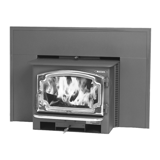
Revere
Fireplace Insert
Copyright 2011, T.I.
$10.00
Owner's Manual
Masonry Fireplace Insert
Zero-Clearance (Metal) Fireplace Insert
Save these instructions
for future reference
100-01165
4110919
Listed
Tested to: U.L. 1482
Advertisement
Table of Contents

Subscribe to Our Youtube Channel
Related Manuals for Travis Industries Revere Fireplace Insert


Summary of Contents for Travis Industries Revere Fireplace Insert
- Page 1 Revere Fireplace Insert Owner's Manual Masonry Fireplace Insert Zero-Clearance (Metal) Fireplace Insert Save these instructions for future reference SAFETY NOTICE: If this appliance is not properly installed, a house fire may result. For your safety, follow the installation directions. Contact local building or fire officials about restrictions and installation inspection requirements in your area.
-
Page 2: Introduction
Introduction Introduction We welcome you as a new owner of a Lopi Revere wood-burning insert. In purchasing a Lopi Revere you have joined the growing ranks of concerned individuals whose selection of an energy system reflects both a concern for the environment and aesthetics. The Lopi Revere is one of the finest appliances the world over. -
Page 3: Table Of Contents
Table of Contents Optional Blower Operation ......18 Introduction ............2 Re-Loading the Insert ........18 Important Information ........2 Overnight Burn ..........18 Installation Options .......... 6 Normal Operating Sounds ......18 ... - Page 4 Safety Precautions The viewing door must be Gasoline or other flammable closed and latched during liquids must never be used to operation. start the fire or "Freshen Up" the fire. Do not store or use Smoke from this appliance may gasoline or other flammable active a smoke detector when liquids in the vicinity of this...
- Page 5 Safety Precautions When installed in a mobile home, this appliance must be Do not place clothing or other bolted to the floor, have outside flammable items on or near this air, and not be installed in the appliance. Mobile bedroom (Per H.U.D. Home requirements).
-
Page 6: Installation Options
Features & Specifications Installation Options Features Masonry Fireplace Insert EPA Phase II Approved Zero-Clearance (Metal) Fireplace Insert 2.2 Cubic Foot Firebox Volume Single Operating Control Accepts Logs Up to 18" Long Steel Plate Construction (5/16" & 3/16") ... -
Page 7: Planning The Installation
Stove Installation (for qualified installers only) SAFETY NOTICE: Please read this entire manual before you install and use your new room heater. Failure to follow instructions may result in property damage, bodily injury, or even death. Contact local building or fire officials about restrictions and installation inspection requirements in your area. -
Page 8: Fireplace Requirements
Stove Installation (for qualified installers only) Fireplace Requirements The diagram below shows the minimum size requirements for the type of fireplace used. Minimum Fireplace Masonry Z.C. (Metal) Size Fireplace Fireplace 19.75" 19.75" a Height (front) 502mm 502mm 19.75" 19.75" b Height (rear) 362mm 502mm 24.25"... -
Page 9: Insert Placement Requirements
Stove Installation (for qualified installers only) Insert Placement Requirements The insert must be placed so that no combustibles are within, or can swing within (e.g. drapes, doors), 36" of the front of the insert. Insert and hearth must be installed on a level, secure floor. ... -
Page 10: Hearth Requirements
Stove Installation (for qualified installers only) Hearth Requirements Must extend in front of the insert and on both sides (see Insert Placement Requirements for details) Must be non-combustible and at least .018" thick (26 gauge) Drafting Performance This appliance relies upon natural draft to operate. External forces, such as wind, barometric pressure, topography, or factors of the home (negative pressure from exhaust fans, chimneys, air infiltration, etc.), may adversely affect draft. -
Page 11: Block-Off Plate Installation
Stove Installation (for qualified installers only) Block-Off Plate Installation Whenever this appliance is installed with a direct connection a block-off plate, or other non-combustible seal-off device (e.g. damper adapter), will need to be installed. This device is used to seal the chimney, insuring no smoke enters the home and providing the chimney system with a seal to promote draft. -
Page 12: Insert With Positive Connection
Stove Installation (for qualified installers only) Install a non-combustible Insert with Cap (prevents water cover plate to prevent water Positive from entering) from entering the chimney Connection NOTE: This installation may be NOTE: used with a masonry or zero Flue Liner Most factory-built clearance fireplace. -
Page 13: Insert With Direct Connection (Z.c. Fireplace)
Stove Installation (for qualified installers only) NOTE: This installation may be Insert with Direct used with a masonry or zero Connection (Z.C. clearance fireplace. This Fireplace) illustration depicts a zero clearance insert, all requirements in the section "Zero Clearance Stainless steel Fireplace Requirements"... -
Page 14: Safety Notice
Operating Your Appliance Safety Notice If this appliance is not properly installed, a house fire may result. For your safety, follow the installation directions. Contact local building or fire officials about restrictions and installation inspection requirements in your area. Read and follow all of the warnings on pages 4 and 5 of this manual. Before Your First Fire Verify the Installation Before starting the Insert, verify that the Insert is properly installed and all of the requirements in this... -
Page 15: Bypass Operation
Operating Your Appliance Bypass Operation The bypass controls the flow of smoke inside the heater. When pulled out, smoke goes directly up the flue, creating more draft. When pushed in, the smoke goes around the baffle, utilizing the secondary combustion and making the heater more efficient. ... -
Page 16: Starting A Fire
Operating Your Appliance Starting a Fire Since the dawn of time man has debated the best way to start a fire. Some use the boy-scout "tee-pee"; some prefer the "tic-tac-toe" stack. Either way, review the hints and warnings below to ensure proper fire starting. -
Page 17: Adjusting The Burn Rate
Operating Your Appliance Adjusting the Burn Rate Use the air control slider to control the burn rate of the insert. See the illustration below for details. Use the air control to change the burn rate. Low Burn High Burn (air control closed) (air control open) Approximate Air Control Settings Overnight Burn... -
Page 18: Optional Blower Operation
Operating Your Appliance Optional Blower Operation The blower will turn on once the Insert is up to temperature. This is typically 15 to 30 minutes after starting the fire. Follow the directions below to alter the blower speed. HIGH Turn the dial all the way counter- The high position is all the way counter- Turn the dial all the clockwise until it clicks off. -
Page 19: Hints For Burning
Operating Your Appliance Hints for Burning Get the appliance hot before adjusting to low burn Use smaller pieces of wood during start-up and high burns to increase temperature Use larger pieces of wood for overnight or sustained burns ... -
Page 20: Troubleshooting
Operating Your Appliance Troubleshooting Problem Possible Cause Open the air control (pg. 17). Smoke Enters Room During Open the bypass (pg. 15). Start-Up Cold Air Blockage - burn a piece of newspaper to establish a draft. If the flame is not getting enough air, a small crack in the door is all that is needed. -
Page 21: Daily Maintenance (While Insert Is In Use)
Maintaining Your Appliance Failure to properly maintain and inspect your appliance may reduce the performance and life of the appliance, void your warranty, and create a fire hazard. Establish a routine for the fuel, wood burner and firing technique. Check daily for creosote build-up until experience shows how often you need to clean to be safe. -
Page 22: Monthly Maintenance (While Appliance Is In Use)
Maintaining Your Appliance Monthly Maintenance (while appliance is in use) Make sure the appliance has fully cooled prior to conducting service. Door and Glass Inspection The door must form an air-tight seal to the firebox for the Insert to work correctly. Inspect the door gasket to make sure it forms an air-tight seal to the firebox. -
Page 23: Yearly Maintenance
Maintaining Your Appliance Yearly Maintenance Make sure the appliance has fully cooled prior to conducting service. Touch-Up Paint Included with the owner's pack of this appliance is a can of Insert-Brite® paint. To touch up nicks or dulled paint, apply the paint while the appliance is cool. Sand rusted or damaged areas before preparation (use 120-grit sandpaper). -
Page 24: Door Parts
Maintaining Your Appliance Door Parts 1/8” Hex Wrench # 20 Torx Driver NOTE: Place the glass gasket around the perimeter of the door retainer. 9/16" Wrench NOTE: Glue the door gasket to the door retainer. ID # Description Part # ID # Description Part #... -
Page 25: Firebox Parts
Maintaining Your Appliance Firebox Parts ID # Description Part # ID # Description Part # Air Tubes & Sleeve 98900233 Air Tube Roll Pins 98900357 Air Tube Retainer Sleeve 98900356 Baffle Support, Front 99900251 Baffle Support, Rear 99900250 Damper Plate 98900322 Damper Slider 98900343... -
Page 26: Baffle Removal & Replacement
Maintaining Your Appliance Baffle Removal & Replacement Push the front firebricks up and feed them forward, guiding them out the door. Repeat for the rear firebricks. Bypass Rod (& Yoke) Baffle Firebrick Front Baffle Support Bypass Damper Bypass Support Front Air Tube Bypass Gasket Support Tabs Center Baffle Support... - Page 27 Limited 7 Year Warranty To register your TRAVIS INDUSTRIES, INC. 7 Year Warranty, complete the enclosed warranty card and mail it within ten (10) days of the appliance purchase date to: TRAVIS INDUSTRIES, INC., 4800 Harbour Pointe Blvd. SW, Mukilteo, WA 98275. TRAVIS INDUSTRIES, INC. warrants this gas appliance (appliance is defined as the equipment manufactured by Travis Industries, Inc.) to be defect-free in material and workmanship to the original purchaser from the date of purchase as follows: Check with your dealer in advance for any costs to you when arranging a warranty call.
-
Page 28: Listing Label
Listing Label Listing Label © Travis Industries 100-01165 4110919... -
Page 29: Door Shell Installation
Optional Equipment Door Shell Installation Part Numbers: Black # 99300195, Brass # 9930096, Pewter # 99300197 1. Remove the door retainer shipping latch following the directions below. Standard Screwdriver Rotate this shaft 1/4 turn clockwise until the door unlatches. Swing the door retianer open. Remove and discard the shipping latch and nut. - Page 30 Optional Equipment Nickel (Cast Iron) Doors Only Use a socket-head wrench with 5/16” socket to pre-thread the holes 6 revolutions. If you pre-thread move revolutions, it may bottom out and break the head off the screw. Remove and retain the screws. See the photos below.
- Page 31 Optional Equipment Make sure the holes in the retainer line up with the holes on the shell then use a 5/16” nutdriver to secure the shell with the two screws. Tighten until the door shell is snug against the retainer (do not over-tighten).
-
Page 32: Surround Panels
Optional Equipment Surround Panels Rectangular Panels SURROUND PANEL SIZE HEIGHT WIDTH 8" 27 5/8" 40 3/8 " 10" 29 5/8" 44 3/8 " 12" 31 5/8" 48 3/8 " Arched Panels (Part # 99300109) 40-1/4” 32-1/4” 24-1/2” Radius = 40-3/4” Installation Instructions With the insert 12”... - Page 33 Optional Equipment 2. Adjust the position of the side panels so they are: 1) flush with the bottom of the insert; 2) both the same distance back from the front of the insert; 3) perpendicular to the floor (use the top panel, if necessary, to judge alignment).
-
Page 34: Front Blower (Part # 99000128)
Optional Equipment Front Blower (part # 99000128) Switching the Power Cord to the Left Side Use a pair of pliers to disconnect the strain relief which holds the power cord in place. With the power cord slackened, the Molex connectors that attach the power cord to the blower assembly may be disconnected. - Page 35 Optional Equipment © Travis Industries 100-01165 4110919...
- Page 36 Index Additional Accessories Needed for Installation .. 7 Insert with Direct Connection (Z.C. Fireplace) . 13 Adjusting the Burn Rate ........17 Insert with Positive Connection ......12 Air Tube Removal & Replacement ....26 Installation Considerations ......... 7 Approximate Air Control Settings ..... 17 Installation Instructions ........
Need help?
Do you have a question about the Revere Fireplace Insert and is the answer not in the manual?
Questions and answers