Table of Contents
Advertisement
Advertisement
Table of Contents

Related Manuals for Husqvarna 1130ST


Summary of Contents for Husqvarna 1130ST
- Page 1 1130ST Owner's Manual...
-
Page 2: Safety Rules
Safe Operation Practices for Snow Throwers IMPORTANT: This machine is capable of amputating hands and feet and throwing objects. Failure to observe the following safety instructions could result in serious injury or death. Look for this symbol to point out im- por tant safety precautions. -
Page 3: Maintenance And Storage
• Do not put hands or feet near or under rotating parts. Keep clear of the discharge opening and front auger area at all times. • Exercise extreme caution when op er at ing on or cross- ing gravel drives, walks or roads. Stay alert for hidden hazards or traffi... -
Page 4: Table Of Contents
SAFETY RULES ... 2-3 PRODUCT SPECIFICATIONS ... 3 CUSTOMER RESPONSIBILITIES... 3 WARRANTY... 32 ASSEMBLY / PRE-OPERATION ... 5-7 OPERATION ... 8-13 PARTS PACKED SEPARATELY IN CARTON MAINTENANCE ... 14-15 MAINTENANCE SCHEDULE ... 14 SERVICE AND AD JUST MENTS ... 16-18 STORAGE ... -
Page 5: Assembly / Pre-Operation
ASSEMBLY / PRE-OPERATION Read these instructions and this man u al in its entirety before you attempt to assemble or operate your new snow thrower. Your new snow thrower has been as sem bled at the factory with the ex cep tion of those parts left unassembled for shipping purposes. - Page 6 ASSEMBLY / PRE-OPERATION INSTALL TRACTION DRIVE CONTROL ROD (See Figs. 3 and 4) The traction drive control rod has the long loop on the end of the spring as shown. 1. Slide rubber sleeve up rod and hook end of spring into pivot bracket with loop opening down as shown.
-
Page 7: Check Tire Pressure
ASSEMBLY / PRE-OPERATION INSTALL DISCHARGE CHUTE / CHUTE ROTATER HEAD (See Fig. 7) NOTE: The multi-wrench provided in your parts bag may be used to install the chute rotater head. 1. Place discharge chute assembly on top of chute base with discharge opening toward front of snow thrower. -
Page 8: Know Your Snow Thrower
OPERATION KNOW YOUR SNOW THROWER READ THIS OWNER'S MANUAL AND ALL SAFETY RULES BEFORE OPERATING YOUR SNOW THROWER. Compare the illustrations with your snow thrower to familiarize yourself with the location of various controls and adjustments. Save this manual for future reference. These symbols may appear on your snow thrower or in literature supplied with the product. - Page 9 SPARK PLUG SAFETY IGNITION CHOKE CON- TROL THROTTLE / ENGINE CONTROL RECOIL POWER (AUXILIARY) CORD STARTER PLUG ELECTRIC HANDLE START BUTTON PRIM ER NOTE: ITEMS ABOVE ARE SHOWN IN THEIR TYPICAL LOCATION ON THE ENGINE. ACTUAL LOCATION MAY VARY WITH THE ENGINE ON YOUR UNIT.
-
Page 10: How To Use Your Snow Thrower
The operation of any snow thrower can result in foreign objects thrown into the eyes, which can result in severe eye damage. Always wear safety glasses or eye shields while operating your snow thrower or performing any ad just - 00155 ments or repairs. - Page 11 • Press downward on chute defl ector control lever and move lever forward to lower the defl ector and decrease the distance. Move lever back to raise the defl ector and increase the distance. Be sure lever springs back and locks into desired position. TO THROW SNOW (See Fig.
-
Page 12: Before Starting The Engine
• If snow thrower must be operated over gravel surface, use extra caution and be sure skid plates are adjusted to lowest (highest scraper clear ance) position. 1. Shut off engine and wait for all moving parts to stop. 2. Adjust skid plates by loosening the rear 1/2" hex nut only, then moving skid plate to desired position. -
Page 13: Cold Start - Electric Starter
COLD START - ELECTRIC STARTER 1. Insert safety ignition key into the ignition slot until it clicks. DO NOT turn the key. Keep the extra safety ignition key in a safe place. 2. Place throttle control in FAST position. 3. Rotate choke control to FULL position. 4. -
Page 14: Before Each Use
GENERAL REC OM MEN DA TIONS The warranty on this snow thrower does not cover items that have been sub ject ed to operator abuse or negligence. To receive full value from the warranty, operator must maintain snow thrower as in struct ed in this manual. Some ad just - ments will need to be made periodically to properly maintain your snow thrower. - Page 15 V-BELTS Check V-belts for deterioration and wear after every 50 hours of operation and replace if necessary. The belts are not ad just able. Replace belts if they begin to slip from wear. (See “TO REMOVE BELT COVER” in the Service and Adjustments section of this manual).
-
Page 16: Service And Adjustments
SERVICE AND ADJUSTMENTS WARNING: To avoid serious injury, before performing any service or ad- just ments: 1. Be sure throttle is in STOP position. 2. Remove safety ignition key. 3. Make sure the augers and all mov ing parts have completely stopped. 4. -
Page 17: Service And Adjustments
SERVICE AND ADJUSTMENTS TO REPLACE BELTS (See Fig. 23) The auger and traction drive belts are not adjustable. If the belts are damaged or begin to slip from wear, they should be replaced. It is recommended that the belt(s) be replaced by a qualifi... -
Page 18: Storage
TO REMOVE WHEELS (See Fig. 24) • Remove the klik pin and remove wheel from axle. IMPORTANT: When installing wheel, be sure to use the axle hole closest to the end of the shaft – do not use the hole in the wheel hub (if equipped). Inner hole in axle and hole in wheel hub are not used for your model snow thrower. -
Page 19: Troubleshooting
TROUBLESHOOTING See appropriate section in manual unless directed to a qualifi ed service center. PROBLEM CAUSE Does not start 1. Fuel shut-off valve (if so equipped) in OFF position. 2. Safety ignition key is not inserted. 3. Out of fuel. 4. -
Page 20: Repair Parts
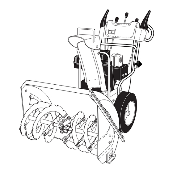
REPAIR PARTS SNOW THROWER - - MODEL NO. 1130ST (HU1130STB), PRODUCT NO. 954 22 30-81 AUGER HOUSING / IMPELLER ASSEMBLY 28 19 44 27 24 25 28 19... - Page 21 REPAIR PARTS SNOW THROWER - - MODEL NO. 1130ST (HU1130STB), PRODUCT NO. 954 22 30-81 KEY PART 532 18 87-03 Bar, Weight 532 16 67-85 Nut, Hex 5/16-18 872 11 05-10 Bolt, Carriage 5/16-18 x 1-1/4 532 18 10-83 Pulley, Impeller...
-
Page 22: Control Panel / Discharge Chute
REPAIR PARTS SNOW THROWER - - MODEL NO. 1130ST (HU1130STB), PRODUCT NO. 954 22 30-81 CONTROL PANEL / DISCHARGE CHUTE... - Page 23 REPAIR PARTS SNOW THROWER - - MODEL NO. 1130ST (HU1130STB), PRODUCT NO. 954 22 30-81 CONTROL PANEL / DISCHARGE CHUTE KEY PART DESCRIPTION 532 18 33-34 Knob, Lever 817 50 10-10 Screw #10-24 x 5/8 532 17 86-74 Control Assembly, Defl ector...
- Page 24 REPAIR PARTS HANDLES SNOW THROWER - - MODEL NO. 1130ST (HU1130STB), PRODUCT NO. 954 22 30-81...
- Page 25 REPAIR PARTS SNOW THROWER - - MODEL NO. 1130ST (HU1130STB), PRODUCT NO. 954 22 30-81 KEY PART NOTE: All component dimensions given in U.S. inches DESCRIPTION 532 18 41-10 Lever, Auger Control, RH 532 18 41-09 Lever, Traction Drive Control, LH...
- Page 26 REPAIR PARTS SNOW THROWER - - MODEL NO. 1130ST (HU1130STB), PRODUCT NO. 954 22 30-81 9 10 DRIVE...
- Page 27 REPAIR PARTS SNOW THROWER - - MODEL NO. 1130ST (HU1130STB), PRODUCT NO. 954 22 30-81 KEY PART NOTE: All component dimensions given in U.S. inches DESCRIPTION 532 14 63-15 Screw, Hex Head 5/16-18 x 3/4 873 80 05-00 Nut, Lock 5/16-18...
- Page 28 REPAIR PARTS SNOW THROWER - - MODEL NO. 1130ST (HU1130STB), PRODUCT NO. 954 22 30-81 53 54 CHASSIS / ENGINE / PULLYS 10 21...
- Page 29 REPAIR PARTS SNOW THROWER - - MODEL NO. 1130ST (HU1130STB), PRODUCT NO. 954 22 30-81 KEY PART 532 18 10-44 Spring, Traction Idler 532 18 05-22 Pulley, Idler (2-1/4) - - - 874 78 05-20 Screw, Hex Head 5/16-18 x 1-1/4...
-
Page 30: Repair Parts
REPAIR PARTS SNOW THROWER - - MODEL NO. 1130ST (HU1130STB), PRODUCT NO. 954 22 30-81 32 30 1 13 32 30 25 24 WHEELS / DECALS... -
Page 31: Repair Parts
REPAIR PARTS SNOW THROWER - - MODEL NO. 1130ST (HU1130STB), PRODUCT NO. 954 22 30-81 KEY PART KEY PART NOTE: All component dimensions given in U.S. inches DESCRIPTION 532 18 78-32 Wheel Assembly, 16", Power Steering, LH 532 15 54-43 Pin, Klik 1/4... -
Page 32: Warranty
532 18 78-28 Rev. 1 03.03.04 BY Printed in U.S.A.
Need help?
Do you have a question about the 1130ST and is the answer not in the manual?
Questions and answers