Table of Contents
Advertisement
Advertisement
Table of Contents

Related Manuals for Husqvarna 1130STE XP


Summary of Contents for Husqvarna 1130STE XP
- Page 1 1130STE XP Owner's Manual...
-
Page 2: Safety Rules
Safe Operation Practices for Snow Throwers IMPORTANT: This machine is capable of amputating hands and feet and throwing objects. Failure to observe the following safety instructions could result in serious injury or death. Look for this symbol to point out im- por tant safety precautions. -
Page 3: Maintenance And Storage
• Do not put hands or feet near or under rotating parts. Keep clear of the discharge opening and front auger area at all times. • Exercise extreme caution when op er at ing on or cross- ing gravel drives, walks or roads. Stay alert for hidden hazards or traffi... -
Page 4: Table Of Contents
SAFETY RULES ... 2-3 PRODUCT SPECIFICATIONS ... 3 CUSTOMER RESPONSIBILITIES... 3 WARRANTY... 32 ASSEMBLY / PRE-OPERATION ... 5-7 OPERATION ... 8-14 PARTS PACKED SEPARATELY IN CARTON MAINTENANCE ... 14-15 MAINTENANCE SCHEDULE ... 14 SERVICE AND AD JUST MENTS ... 16-18 STORAGE ... -
Page 5: Assembly / Pre-Operation
ASSEMBLY / PRE-OPERATION Read these instructions and this man u al in its entirety before you attempt to assemble or operate your new snow thrower. Your new snow thrower has been as sem bled at the factory with the ex cep tion of those parts left unassembled for shipping purposes. - Page 6 ASSEMBLY / PRE-OPERATION TRACTION DRIVE CON TROL LEVER DRIVE CONTROL BRACKET FIG. 4 INSTALL AUGER CONTROL ROD (See Figs. 5 and 6) The auger control rod has the short loop on the end of the spring as shown. 1. Slide rubber sleeve up rod and hook end of spring into control arm with loop opening up as shown.
- Page 7 ASSEMBLY / PRE-OPERATION INSTALL CHUTE DEFLECTOR REMOTE CONTROL (See Figs. 8 and 9) 1. Install remote cable bracket to discharge chute with 5/16-18 carriage bolt, 5/16 fl at washer and 5/16-18 locknut as shown. Tighten securely. 2. Install remote cable eyelet to chute defl ector with 1/4-20 shoulder bolt, nylon friction washer and 1/4-20 locknut as shown.
-
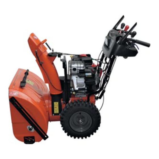
Page 8: Know Your Snow Thrower
OPERATION KNOW YOUR SNOW THROWER READ THIS OWNER'S MANUAL AND ALL SAFETY RULES BEFORE OPERATING YOUR SNOW THROWER. Compare the illustrations with your snow thrower to familiarize yourself with the location of various controls and adjustments. Save this manual for future reference. These symbols may appear on your snow thrower or in literature supplied with the product. - Page 9 SPARK PLUG SAFETY IGNITION CHOKE CON- TROL THROTTLE / ENGINE CONTROL RECOIL POWER (AUXILIARY) CORD STARTER PLUG ELECTRIC HANDLE START BUTTON PRIM ER NOTE: ITEMS ABOVE ARE SHOWN IN THEIR TYPICAL LOCATION ON THE ENGINE. ACTUAL LOCATION MAY VARY WITH THE ENGINE ON YOUR UNIT.
-
Page 10: How To Use Your Snow Thrower
The operation of any snow thrower can result in foreign objects thrown into the eyes, which can result in severe eye damage. Always wear safety glasses or eye shields while operating your snow thrower or performing any ad just - ments or repairs. - Page 11 TO THROW SNOW (See Fig. 16) The auger rotation is controlled by the auger control lever located on the right side handle. • Squeeze auger control lever to handle to engage the auger and throw snow. • Release the auger control lever to stop throwing snow. AUGER CONTROL LEVER...
-
Page 12: Before Starting The Engine
TO ADJUST SKID PLATES (See Fig. 20) NOTE: The wrench provided in your parts bag may be used to adjust the skid plates. Skid plates are located on each side of the auger housing and adjust the clearance between the scraper bar and the ground surface. -
Page 13: Snow Throwing Tips
TO START ENGINE • Be sure fuel shut-off valve is in the OPEN position. Your snow thrower engine is equipped with both a 120 Volt A.C. electric starter and a recoil starter. The electric starter is equipped with a three-wire power cord and plug and is designed to operate on 120 Volt A.C. -
Page 14: General Recommendations
• For extremely heavy snow, re duce the width of snow removal by over lap ping previous path and moving slowly. • Keep engine clean and clear of snow during use. This will help air fl ow and extend engine life. •... -
Page 15: Snow Thrower
SNOW THROWER Always observe safety rules when performing main te nance. TIRES • Maintain proper air pressure in both tires (See “PROD- UCT SPECIFICATIONS” section in this manual). • Keep tires free of gasoline / oil, which can harm rubber. NOTE: To seal tire punctures and prevent fl... -
Page 16: Service And Adjustments
SERVICE AND ADJUSTMENTS WARNING: To avoid serious injury, before performing any service or ad- just ments: 1. Be sure throttle is in STOP position. 2. Remove safety ignition key. 3. Make sure the augers and all mov ing parts have completely stopped. 4. -
Page 17: Service And Adjustments
SERVICE AND ADJUSTMENTS TO REPLACE BELTS (See Fig. 25) The auger and traction drive belts are not adjustable. If the belts are damaged or begin to slip from wear, they should be replaced. It is recommended that the belt(s) be replaced by a qualifi... -
Page 18: Storage
TO REMOVE WHEELS (See Fig. 26) • Remove the klik pin and remove wheel from axle. IMPORTANT: When installing wheel, be sure to use the axle hole closest to the end of the shaft – do not use the hole in the wheel hub (if equipped). Inner hole in axle and hole in wheel hub are not used for your model snow thrower. -
Page 19: Troubleshooting
TROUBLESHOOTING See appropriate section in manual unless directed to a qualifi ed service center. PROBLEM CAUSE Does not start 1. Fuel shut-off valve (if so equipped) in OFF position. 2. Safety ignition key is not inserted. 3. Out of fuel. 4. -
Page 20: Repair Parts
REPAIR PARTS SNOW THROWER - MODEL NO. 1130STE XP (HU1130STC), PRODUCT NO. 954 22 30-81 AUGER HOUSING / IMPELLER ASSEMBLY 28 19 44 27 24 25 28 19... - Page 21 REPAIR PARTS SNOW THROWER - MODEL NO. 1130STE XP (HU1130STC), PRODUCT NO. 954 22 30-81 KEY PART 532 18 86-63 Bar, Weight 532 16 67-85 Nut, Hex 5/16-18 872 11 05-10 Bolt, Carriage 5/16-18 x 1-1/4 532 19 10-79 Pulley, Impeller...
-
Page 22: Control Panel / Discharge Chute
REPAIR PARTS SNOW THROWER - MODEL NO. 1130STE XP (HU1130STC), PRODUCT NO. 954 22 30-81 CONTROL PANEL / DISCHARGE CHUTE... - Page 23 REPAIR PARTS SNOW THROWER - MODEL NO. 1130STE XP (HU1130STC), PRODUCT NO. 954 22 30-81 CONTROL PANEL / DISCHARGE CHUTE KEY PART DESCRIPTION 532 18 33-34 Knob, Lever 817 50 10-10 Screw #10-24 x 5/8 532 17 86-74 Control Assembly, Defl ector...
- Page 24 REPAIR PARTS HANDLES SNOW THROWER - MODEL NO. 1130STE XP (HU1130STC), PRODUCT NO. 954 22 30-81...
- Page 25 REPAIR PARTS SNOW THROWER - MODEL NO. 1130STE XP (HU1130STC), PRODUCT NO. 954 22 30-81 KEY PART NOTE: All component dimensions given in U.S. inches DESCRIPTION 532 18 41-10 Lever, Auger Control, RH 532 18 41-09 Lever, Traction Drive Control, LH...
- Page 26 REPAIR PARTS SNOW THROWER - MODEL NO. 1130STE XP (HU1130STC), PRODUCT NO. 954 22 30-81 9 10 DRIVE...
- Page 27 REPAIR PARTS SNOW THROWER - MODEL NO. 1130STE XP (HU1130STC), PRODUCT NO. 954 22 30-81 KEY PART NOTE: All component dimensions given in U.S. inches DESCRIPTION 532 14 63-15 Screw, Hex Head 5/16-18 x 3/4 873 80 05-00 Nut, Lock 5/16-18...
-
Page 28: Chassis / Engine / Pulleys
REPAIR PARTS SNOW THROWER - MODEL NO. 1130STE XP (HU1130STC), PRODUCT NO. 954 22 30-81 CHASSIS / ENGINE / PULLEYS 10 21... - Page 29 REPAIR PARTS SNOW THROWER - MODEL NO. 1130STE XP (HU1130STC), PRODUCT NO. 954 22 30-81 KEY PART DESCRIPTION 532 18 10-44 Spring, Traction Idler 532 18 05-22 Pulley, Idler (2-1/4) - - - Engine, Tecumseh, Model Number OH3185A-221807B (For engine...
- Page 30 REPAIR PARTS SNOW THROWER - MODEL NO. 1130STE XP (HU1130STC), PRODUCT NO. 954 22 30-81 32 30 1 13 32 30 25 24 WHEELS / DECALS...
-
Page 31: Repair Parts
REPAIR PARTS SNOW THROWER - MODEL NO. 1130STE XP (HU1130STC), PRODUCT NO. 954 22 30-81 KEY PART KEY PART NOTE: All component dimensions given in U.S. inches DESCRIPTION 532 18 78-32 Wheel Assembly, 16", Power Steering, LH 532 15 54-43 Pin, Klik 1/4... -
Page 32: Warranty
532 19 12-90 Rev. 2 07.30.04 BY Printed in U.S.A.
Need help?
Do you have a question about the 1130STE XP and is the answer not in the manual?
Questions and answers