Table of Contents
Advertisement
Advertisement
Chapters
Table of Contents

Related Manuals for Husqvarna 10530SBEB


Summary of Contents for Husqvarna 10530SBEB
- Page 1 10530SBEB Owner's Manual...
-
Page 2: Safety Rules
Safe Operation Practices for Walk-Behind Snow Throwers This snow thrower is capable of amputating hands and feet and throwing objects. Failure to observe the following safety instructions could result in serious injury. Look for this symbol to point out im- portant safety precautions. -
Page 3: Table Of Contents
6. When cleaning, repairing or inspecting the snow thrower, stop the engine and make certain the collector/impeller and all moving parts have stopped. Disconnect the spark plug wire and keep the wire away from the plug to prevent someone from accidentally starting the en- gine. - Page 4 PARTS PACKED SEPARATELY IN CARTON...
-
Page 5: Assembly / Pre-Operation
ASSEMBLY / PRE-OPERATION Read these instructions and this manual in its entirety before you attempt to assemble or operate your new snow thrower. Reading the entire manual will familiarize you with the unit, which will assist you in assembly, operation and maintenance of the product. Your new snow thrower has been as sembled at the factory with the ex ception of those parts left unassembled for shipping purposes. - Page 6 ASSEMBLY / PRE-OPERATION INSTALL TRACTION DRIVE CONTROL ROD (See Figs. 3 and 4) The traction drive control rod has the long loop on the end of the spring as shown. 1. Slide rubber sleeve up rod and hook end of spring into pivot bracket with loop opening down as shown.
- Page 7 ASSEMBLY / PRE-OPERATION INSTALL DISCHARGE CHUTE / CHUTE ROTATER HEAD (See Fig. 7) NOTE: The multi-wrench provided in your parts bag may be used to install the chute rotater head. 1. Place discharge chute assembly on top of chute base with discharge opening toward front of snow thrower.
-
Page 8: Know Your Snow Thrower
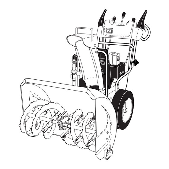
OPERATION KNOW YOUR SNOW THROWER READ THIS OWNER'S MANUAL AND ALL SAFETY RULES BEFORE OPERATING YOUR SNOW THROWER. Compare the illustrations with your snow thrower to familiarize yourself with the location of various controls and adjustments. Save this manual for future reference. These symbols may appear on your snow thrower or in literature supplied with the product. - Page 9 GASOLINE FILLER CAP MUFFLER CHOKE CON- TROL PRIMER SAFETY IGNITION FUEL SHUT-OFF VALVE ON / OFF SWITCH NOTE: ITEMS ABOVE ARE SHOWN IN THEIR TYPICAL LOCATION ON THE ENGINE. ACTUAL LOCATION MAY VARY WITH THE ENGINE ON YOUR UNIT. AUGERS MEETS A.N.S.I.
-
Page 10: How To Use Your Snow Thrower
The operation of any snow thrower can result in foreign objects thrown into the eyes, which can result in severe eye damage. Always wear safety glasses or eye shields while operating your snow thrower or performing any ad just- ments or repairs. We recommend standard safe ty glasses or a wide vision safety mask worn over spectacles. - Page 11 TO THROW SNOW (See Fig. 14) The auger rotation is controlled by the auger control lever located on the right side handle. • Squeeze auger control lever to handle to engage the auger and throw snow. • Release the auger control lever to stop throwing snow. AUGER CONTROL LEVER...
-
Page 12: Before Starting The Engine
TO ADJUST SKID PLATES (See Fig. 18) NOTE: The wrench provided in your parts bag may be used to adjust the skid plates. Skid plates are located on each side of the auger housing and adjust the clearance between the scraper bar and the ground surface. -
Page 13: If Recoil Starter Has Frozen
COLD START - ELECTRIC STARTER 1. Insert safety ignition key (packed separately in parts bag) into ignition slot until it clicks. DO NOT turn the key. Keep the extra safety ignition key in a safe place. 2. Place ON / OFF switch in “ON” position. 3. -
Page 14: Maintenance
GENERAL REC OMMENDA TIONS The warranty on this snow thrower does not cover items that have been sub jected to operator abuse or negligence. To receive full value from the warranty, operator must maintain snow thrower as in structed in this manual. Some ad just- ments will need to be made periodically to properly maintain your snow thrower. - Page 15 V-BELTS Check V-belts for deterioration and wear after every 50 hours of operation and replace if necessary. The belts are not ad justable. Replace belts if they begin to slip from wear. (See “TO REMOVE BELT COVER” in the Service and Adjustments section of this manual).
-
Page 16: Service And Adjustments
SERVICE AND ADJUSTMENTS WARNING: To avoid serious injury, before per- forming any service or ad justments: 1. Be sure throttle is in STOP position. 2. Remove safety ignition key. 3. Make sure the augers and all mov ing parts have completely stopped. 4. -
Page 17: To Replace Belts
SERVICE AND ADJUSTMENTS TO REPLACE BELTS (See Fig. 22) The auger and traction drive belts are not adjustable. If the belts are damaged or begin to slip from wear, they should be replaced. It is recommended that the belt(s) be replaced by a qualifi... -
Page 18: Storage
TO REMOVE WHEELS (See Fig. 23) • Remove the klik pin and remove wheel from axle. IMPORTANT: When installing wheel, be sure to use the axle hole closest to the end of the shaft – do not use the hole in the wheel hub (if equipped). Inner hole in axle and hole in wheel hub are not used for your model snow thrower. -
Page 19: Troubleshooting
TROUBLESHOOTING See appropriate section in manual unless directed to an authorized service centre/department. PROBLEM CAUSE Does not start 1. Fuel shut-off valve (if so equipped) in OFF position. 2. Safety ignition key is not inserted. 3. Out of fuel. 4. Throttle in STOP position (or ON/OFF switch is OFF). -
Page 20: Repair Parts
REPAIR PARTS SNOW THROWER - MODEL NO. 10530SBEB (96193001300), PRODUCT NO. 961 93 00-13 AUGER HOUSING / IMPELLER ASSEMBLY 28 19 28 19... - Page 21 REPAIR PARTS SNOW THROWER - MODEL NO. 10530SBEB (96193001300), PRODUCT NO. 961 93 00-13 532 19 10-79 Pulley, Impeller 532 18 89-09 Bearing Assembly, Flange 532 15 53-77 Nut, Hex Flange 5/16-18 532 18 03-55 Bolt, Flat Head, Carriage 5/16-18 x 5/8...
-
Page 22: Control Panel / Discharge Chute
REPAIR PARTS SNOW THROWER - MODEL NO. 10530SBEB (96193001300), PRODUCT NO. 961 93 00-13 CONTROL PANEL / DISCHARGE CHUTE... - Page 23 REPAIR PARTS SNOW THROWER - MODEL NO. 10530SBEB (96193001300), PRODUCT NO. 961 93 00-13 KEY PART NOTE: All component dimensions given in U.S. inches. IMPORTANT: Use only Original Equipment Manufacturer (O.E.M.) replacement parts. Failure to do so could be hazardous, damage your lawn mower and void your warranty.
- Page 24 REPAIR PARTS SNOW THROWER - MODEL NO. 10530SBEB (96193001300), PRODUCT NO. 961 93 00-13 HANDLES...
-
Page 25: Key Part No
REPAIR PARTS SNOW THROWER - MODEL NO. 10530SBEB (96193001300), PRODUCT NO. 961 93 00-13 KEY PART NOTE: All component dimensions given in U.S. inches. IMPORTANT: Use only Original Equipment Manufacturer (O.E.M.) replacement parts. Failure to do so could be hazardous, damage your lawn mower and void your warranty. - Page 26 REPAIR PARTS SNOW THROWER - MODEL NO. 10530SBEB (96193001300), PRODUCT NO. 961 93 00-13 DRIVE 9 10...
-
Page 27: 819 11 15-07 Washer, Flat
REPAIR PARTS SNOW THROWER - MODEL NO. 10530SBEB (96193001300), PRODUCT NO. 961 93 00-13 KEY PART NOTE: All component dimensions given in U.S. inches. IMPORTANT: Use only Original Equipment Manufacturer (O.E.M.) replacement parts. Failure to do so could be hazardous, damage your lawn mower and void your warranty. -
Page 28: Chassis / Engine / Pulleys
REPAIR PARTS SNOW THROWER - MODEL NO. 10530SBEB (96193001300), PRODUCT NO. 961 93 00-13 CHASSIS / ENGINE / PULLEYS 10 21... -
Page 29: 532 18 56-00 Bolt, Shoulder
REPAIR PARTS SNOW THROWER - MODEL NO. 10530SBEB (96193001300), PRODUCT NO. 961 93 00-13 KEY PART DESCRIPTION 532 18 10-44 Spring, Traction Idler 532 18 05-22 Pulley, Idler (2-1/4) - - - Engine, Briggs & Stratton, Model Number 20E114 (For engine service and replacement parts, call Briggs &... - Page 30 REPAIR PARTS SNOW THROWER - MODEL NO. 10530SBEB (96193001300), PRODUCT NO. 961 93 00-13 15 12 1 13 WHEELS / DECALS...
- Page 31 REPAIR PARTS SNOW THROWER - MODEL NO. 10530SBEB (96193001300), PRODUCT NO. 961 93 00-13 KEY PART KEY PART NOTE: All component dimensions given in U.S. inches. IMPORTANT: Use only Original Equipment Manufacturer (O.E.M.) replacement parts. Failure to do so could be hazardous, damage your lawn mower and void your warranty.
-
Page 32: Warranty
532 40 37-62 Rev. 3 06.06.06 BY Printed in U.S.A.
Need help?
Do you have a question about the 10530SBEB and is the answer not in the manual?
Questions and answers