Table of Contents
Advertisement
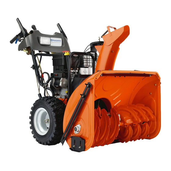
Operator's Manual
12527HV
Gasoline containing up to 10% ethanol (E10) is acceptable for use in this machine.
The use of any gasoline exceeding 10% ethanol (E10) will void the product warranty.
Please read the owner's manual carefully and make sure you
532 44 34-58
English
understand the instructions before using the machine.
Advertisement
Table of Contents

Related Manuals for Husqvarna 12527HV


Summary of Contents for Husqvarna 12527HV
- Page 1 Operator’s Manual 12527HV Gasoline containing up to 10% ethanol (E10) is acceptable for use in this machine. The use of any gasoline exceeding 10% ethanol (E10) will void the product warranty. Please read the owner's manual carefully and make sure you...
-
Page 2: Safety Rules
IMPORTANT Safe Operation Practices for Walk-Behind Snow Throwers This snow thrower is capable of amputating hands and feet and throwing objects. Failure to observe the following safety instructions could result in serious injury. WARNING: Snow throwers have ex- Look for this symbol to point out im- posed rotating parts, which can cause por tant safety precautions. -
Page 3: Table Of Contents
Clearing a Clogged Discharge Chute 6. When cleaning, repairing or inspecting the snow thrower, stop the engine and make certain the collector/impel- Hand contact with the rotating impeller inside the discharge ler and all moving parts have stopped. Disconnect chute is the most common cause of injury associated with the spark plug wire and keep the wire away from the snow throwers. - Page 4 PARTS PACKED SEPARATELY IN CARTON (1) POWER CORD (1) MULTI- (198563) WRENCH (180684) (3) RETAINER SPRINGS (169675) (6) LOCKNUTS (6) SHEAR BOLTS 1/4-20 x 1-3/4 1/4-20 (192090) (2) FLAT WASHERS (73800400) (2) CARRIAGE BOLTS 3/8-16 x 2.25 SAFTEY IGNITION KEY(S) (1) LOCKNUT 3/8 (1) WASHER 3/8 (443059)
-
Page 5: Assembly / Pre-Operation
ASSEMBLY / PRE-OPERATION Read these instructions and this manual in its entirety before you attempt to assemble or operate your new snow thrower. Reading the entire manual will familiarize you with the unit, which will assist you in assembly, operation and maintenance of the product. Your new snow thrower has been as sem bled at the factory with the ex cep tion of those parts left unassembled for shipping purposes. - Page 6 ASSEMBLY / PRE-OPERATION INSTALL AUGER CONTROL ROD (See Figs. 5 and 6) INSTALL TRACTION DRIVE CONTROL ROD (See Figs. 3 and 4) 1. Retrieve vinyl sleeve and spring from bag of parts and retrieve the auger control rod from carton chute tray. The traction drive control rod is installed on the snow Slide straight rod end through the small hole in the thrower.
- Page 7 ASSEMBLY / PRE-OPERATION INSTALL DISCHARGE CHUTE / CHUTE ROTATOR INSTALL CHUTE DEFLECTOR REMOTE CONTROL HEAD (See Fig. 7) (See Figs. 8 and 9) 1. Install remote cable bracket to discharge chute with NOTE: The multi-wrench provided in your parts bag may 5/16-18 carriage bolt and 5/16-18 locknut as shown.
-
Page 8: Operation
OPERATION KNOW YOUR SNOW THROWER READ THIS OWNER'S MANUAL AND ALL SAFETY RULES BEFORE OPERATING YOUR SNOW THROWER. Compare the illustrations with your snow thrower to familiarize yourself with the location of various controls and adjustments. Save this manual for future reference. These symbols may appear on your snow thrower or in literature supplied with the product. - Page 9 OPERATION MUF FLER ELECTRIC AUGER DISCHARGE CHUTE CONTROL LEVER START CONTROL BUTTON LEVER TRACTION DEFLECTOR DRIVE SPEED GAS O LINE DRIVE CON TROL LEVER REMOTE FILLER CAP POWER CONTROL CONTROL CORD LEVER LEVER PLUG CHOKE CHUTE CON- DE FLEC TOR TROL SAFETY LH TURN...
- Page 10 OPERATION The operation of any snow thrower can result TO CONTROL SNOW DISCHARGE (See Fig. 13) in foreign objects thrown into the eyes, which can result in severe eye damage. Always wear WARNING: Snow throwers have ex- safety glasses or eye shields while operating posed rotating parts, which can cause your snow thrower or performing any ad just- severe injury from contact, or from ma-...
- Page 11 OPERATION TO MOVE FORWARD AND BACKWARD (See Fig. 16) USING THE CLEAN-OUT TOOL (See Fig. 15) SELF-PROPELLING, forward and reverse movement of In certain snow conditions, the discharge chute may be- the snow thrower, is controlled by the traction drive control come clogged with ice and snow.
-
Page 12: Before Starting The Engine
OPERATION BEFORE STARTING THE ENGINE TO ADJUST SKID PLATES (See Fig. 18) NOTE: The wrench provided in your parts bag may be CHECK ENGINE OIL LEVEL (See Fig. 19) used to adjust the skid plates. The engine on your snow thrower has been shipped from Skid plates are located on each side of the auger housing and the factory already filled with oil. -
Page 13: Snow Throwing Tips
OPERATION TO START ENGINE 6. When the engine starts, release the recoil starter han dle and slowly move the choke control to the “OFF” position. • Be sure fuel shut-off valve is in the “OPEN” position. Allow the engine to warm up for a few minutes. Engine will Your snow thrower engine is equipped with both a 120 Volt not develop full power until it has reached normal operat- A.C. -
Page 14: Maintenance Schedule
MAINTENANCE LUBRICATION CHART GENERAL REC OM MEN DA TIONS The warranty on this snow thrower does not cover items that have been sub ject ed to operator abuse or negligence. ➀ SAE 30 Motor Oil To receive full value from the warranty, operator must ➁... - Page 15 MAINTENANCE SNOW THROWER Check the crankcase oil level before starting the engine and after each five (5) hours of continuous use. Tighten oil fill Always observe safety rules when performing main te nance. cap / dipstick securely each time you check the oil level. TIRES TO CHANGE ENGINE OIL •...
-
Page 16: Service And Adjustments
SERVICE AND ADJUSTMENTS To replace the capscrew/shear bolts: WARNING: To avoid serious injury, before 1. Disengage all controls and move throttle control to performing any service or ad just ments: STOP position. Wait for all moving parts to stop. 1. Be sure the on/off switch is in the 2. -
Page 17: To Replace Belts
SERVICE AND ADJUSTMENTS TO REPLACE BELTS (See Fig. 22) 8. RELIEVE TENSION ON TRACTION DRIVE BELT IDLER and remove traction drive belt from around The auger and traction drive belts are not adjustable. If pulleys. the belts are damaged or begin to slip from wear, they should be replaced. - Page 18 SERVICE AND ADJUSTMENTS ENGINE SPEED TO REMOVE WHEELS (See Fig. 23) Never tamper with the engine governor, which is factory set • Remove the wheel pin and retainer pin and remove for proper engine speed. Overspeeding the engine above wheel from axle. the factory high speed setting can be dangerous and will NOTE: To seal punctures or prevent flat tires due to slow void the warranty.
-
Page 19: Storage
STORAGE Immediately prepare your snow thrower for storage at • Empty the fuel tank by starting the engine and letting it run until the fuel lines and car bu re tor are empty. the end of the season or if the unit will not be used for 30 days or more. -
Page 20: Troubleshooting
TROUBLESHOOTING See appropriate section in manual unless directed to a service center/department. PROBLEM CAUSE CORRECTION Does not start 1. Fuel shut-off valve (if so equipped) 1. Turn fuel shut-off valve to OPEN position. in OFF position. 2. Safety ignition key is not inserted. 2. - Page 21 SERVICE NOTES...
- Page 26 SERVICE NOTES...
- Page 27 SERVICE NOTES...
- Page 28 07/27/2011 TH...
Need help?
Do you have a question about the 12527HV and is the answer not in the manual?
Questions and answers
Is there a dipstick with this model? Oil level Husqvarna 12527HV
Yes, the Husqvarna 12527HV has a dipstick for checking the oil level. The instructions mention an "oil fill cap/dipstick" that should be wiped clean, reinserted, screwed tight, and then removed to read the oil level.
This answer is automatically generated