
Subscribe to Our Youtube Channel
Related Manuals for Rohde & Schwarz EMI Test ReceiverESCI


Summary of Contents for Rohde & Schwarz EMI Test ReceiverESCI
- Page 1 Operating Manual EMI Test Receiver R&S ESCI 1166.5950.03 This manual consists of 2 volumes: Volume 1 Printed in the Federal Republic of Germany Test and Measurement Division 1166.6004.12-01 05/04...
- Page 2 Dear Customer, R&S® is a registered trademark of Rohde & Schwarz GmbH & Co. KG Trade names are trademarks of the owners. 1166.6004.12-01 05/04...
- Page 3 R&S ESCI Tabbed Divider Overview Tabbed Divider Overview Volume 1 - Operating Manual - Manual Control Data Sheet Safety Instructions Certificate of Quality EU Certificate of Conformity Support Center Address List of R&S Representatives Manuals for Test Receiver R&S ESCI Tabbed Divider Chapter 1: Putting into Operation...
-
Page 5: Symbols And Safety Labels
Before putting the product into operation for the first time, make sure to read the following S a f e t y I n s t r u c t i o n s Rohde & Schwarz makes every effort to keep the safety standard of its products up to date and to offer its customers the highest possible degree of safety. -
Page 6: Safety Instructions
Safety Instructions Observing the safety instructions will help prevent personal injury or damage of any kind caused by dangerous situations. Therefore, carefully read through and adhere to the following safety instructions before putting the product into operation. It is also absolutely essential to observe the additional safety instructions on personal safety that appear in other parts of the documentation. - Page 7 Safety Instructions 4. If products/components are mechanically 10. Intentionally breaking the protective earth and/or thermically processed in a manner connection either in the feed line or in the that goes beyond their intended use, product itself is not permitted. Doing so can hazardous substances (heavy-metal dust result in the danger of an electric shock such as lead, beryllium, nickel) may be...
- Page 8 Safety Instructions 19. If a product is to be permanently installed, matching Rohde & Schwarz type (see the connection between the PE terminal on spare parts list). Batteries and storage site and the product's PE conductor must batteries are hazardous waste. Dispose of be made first before any other connection them only in specially marked containers.
- Page 9 Por favor lea imprescindiblemente antes de la primera puesta en funcionamiento las siguientes informaciones de seguridad Informaciones de seguridad Es el principio de Rohde & Schwarz de tener a sus productos siempre al día con los estandards de seguridad y de ofrecer a sus clientes el máximo grado de seguridad. Nuestros productos y todos los equipos adicionales son siempre fabricados y examinados según las normas de seguridad vigentes.
- Page 10 Informaciones de seguridad Tener en cuenta las informaciones de seguridad sirve para tratar de evitar daños y peligros de toda clase. Es necesario de que se lean las siguientes informaciones de seguridad concienzudamente y se tengan en cuenta debidamente antes de la puesta en funcionamiento del producto. También deberán ser tenidas en cuenta las informaciones para la protección de personas que encontrarán en otro capítulo de esta documentación y que también son obligatorias de seguir.
- Page 11 Informaciones de seguridad seguridad (control a primera vista, control de peligro a causa de la radiación conductor protector, medición de resistencia electromagnética. El empresario está de aislamiento, medición de medición de la comprometido a valorar y señalar areas de corriente conductora, control trabajo en las que se corra un riesgo de...
- Page 12 Informaciones de seguridad 12. No utilice nunca el producto si está dañado el 20. En caso de que los productos que son cable eléctrico. Asegure a través de las instalados fijamente en un lugar sean sin medidas de protección y de instalación protector implementado, autointerruptor o adecuadas de que el cable de eléctrico no similares objetos de protección, deberá...
- Page 13 Informaciones de seguridad 27. Baterías y acumuladores no deben de ser 31. Las asas instaladas en los productos sirven expuestos a temperaturas altas o al fuego. solamente de ayuda para el manejo que Guardar baterías y acumuladores fuera del solamente está previsto para personas. Por alcance de los niños.
- Page 15 Certified Quality System DIN EN ISO 9001 : 2000 DIN EN 9100 : 2003 DIN EN ISO 14001 : 1996 DQS REG. NO 001954 QM/ST UM QUALITÄTSZERTIFIKAT CERTIFICATE OF QUALITY CERTIFICAT DE QUALITÉ Sehr geehrter Kunde, Dear Customer, Cher Client, Sie haben sich für den Kauf eines you have decided to buy a Rohde &...
-
Page 16: Customer Support
Customer Support Technical support – where and when you need it For quick, expert help with any Rohde & Schwarz equipment, contact one of our Customer Support Centers. A team of highly qualified engineers provides telephone support and will work with you to find a solution to your query on any aspect of the operation, programming or applications of Rohde &... - Page 17 R&S ESCI Manuals ESCI Contents of Manuals for EMI Test Receiver R&S Operating Manual R&S ESCI The operating manual describes the following models and options of EMI test receiver ESCI: • R&S ESCI • Option FSP-B4 OCXO - reference oscillator •...
- Page 18 Manuals R&S ESCI Service Manual - Instrument The service manual - instrument informs on how to check compliance with rated specifications, on instrument function, repair, troubleshooting and fault elimination. It contains all information required for the maintenance of R&S ESCI by exchanging modules. 1166.6004.12...
-
Page 19: Table Of Contents
R&S ESCI Contents - Preparing for Operation Contents - Chapter 1 " Preparing for Operation " 1 Preparing for Operation..................1.1 Description of Front and Rear Panel Views...................1.1 Front View ..........................1.1 Rear View..........................1.9 Getting Started with the Instrument .....................1.12 Preparing the Instrument for Operation..................1.12 Setting Up the Instrument.......................1.12 Standalone Operation ....................1.12 Safety Instruction for Instruments with Tiltable Feet ............1.13... - Page 20 Contents - Preparing for Operation R&S ESCI Fig. 1-1 Front View 1166.6004.12 I-1.2...
-
Page 21: Preparing For Operation
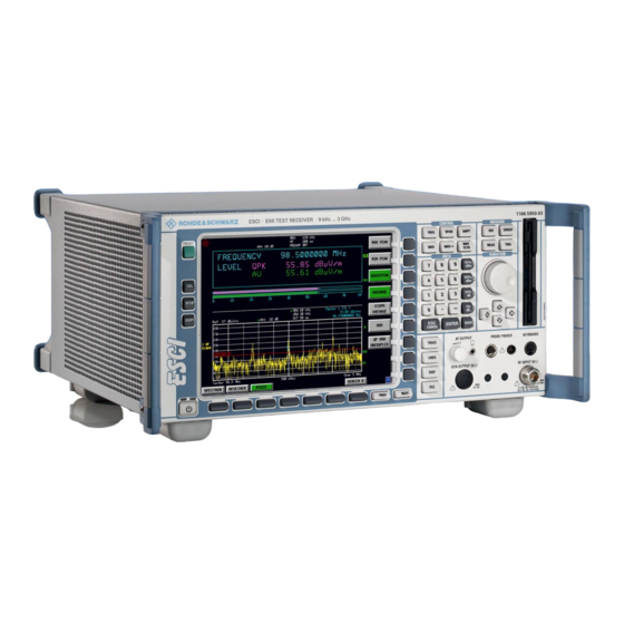
R&S ESCI Front View Preparing for Operation Chapter 1 describes the controls and connectors of the test receiver R&S ESCI by means of the front and rear view. Then follows all the information that is necessary to put the instrument into operation and connect it to the AC supply and to external devices. - Page 22 Front View R&S ESCI Fig. 1-1 Front View 1166.6004.12...
- Page 23 R&S ESCI Front View Keypad for data input see Chapter 3 -dBm GHz s The units keys close the data -dBm V input and define the multipli- cation factor for each basic unit. µs MHz ms For dimension-less or µV dBm mV alphanumeric inputs, the units dB..
- Page 24 Front View R&S ESCI Fig. 1-1 Front View 1166.6004.12...
- Page 25 R&S ESCI Front View Key group for entering data and for cursor movement see Chapter 3 Cursor keys – Move the cursor within the input fields and tables. Vary the input value. – Define the direction of movement – for the roll-key. Roll-key –...
- Page 26 Front View R&S ESCI Fig. 1-1 Front View 1166.6004.12...
- Page 27 R&S ESCI Front View Menu-change keys see Chapter 3 PREV NEXT NEXT Change to side menu PREV Call main menu Hotkeys see Chapter 3 ON/STANDBY switch see Chapter 1 Configure and start a print job see Chapters 1 and 4 HCOPY Define general configuration see Chapter 4...
-
Page 28: Rear View
Rear View R&S ESCI Fig. 1-2 Rear View 1166.6004.12... - Page 29 R&S ESCI Rear View Rear View IEC/IEEE bus-connector 2 for the external see Chapter 8 generator (with Option R&S FSP-B10 only) Power switch and AC power connector see Chapter 1 100 - 240 VAC 3.1 - 1.3 A IEC/IEEE bus-connector see Chapter 8 SCPI Parallel interface connector...
- Page 30 Rear View R&S ESCI Fig. 1-2 Rear View 1166.6004.12 1.10...
- Page 31 R&S ESCI Rear View USB interface see Chapter 8 USER PORT Output/input. TTL levels see Chapter 8 USER PORT (Low < 0,4 V, High > 2 V). Internal +5 V power supply voltage. Maximum load current 100 mA. AUX Control connector for controlling the external AUX CONTROL generator (option R&S FSP-B10 only) REF IN...
-
Page 32: Getting Started With The Instrument
Getting Started with the Instrument R&S ESCI Getting Started with the Instrument The following section describes how to activate the instrument and how to connect external devices such as printer and monitor. Chapter 2 explains the operation of the instrument using simple measurement examples. Important: Prior to switching on the instrument, make sure that the following conditions are fulfilled: •... -
Page 33: Safety Instruction For Instruments With Tiltable Feet
R&S ESCI Getting Started with the Instrument Safety Instruction for Instruments with Tiltable Feet Warning The feet must be fully folded in or out. Only in this way can the stability of the instrument be guaranteed and reliable operation be ensured. With the feet out, the total load for the feet must not exceed 500 N (own weight and additional units put onto the instrument). -
Page 34: Emc Safety Precautions
Getting Started with the Instrument R&S ESCI EMC Safety Precautions In order to avoid electromagnetic interference (EMI), the instrument may be operated only with all covers closed. Only adequately shielded signal and control cables may be used (see recommended accessories). Connecting the Instrument to the AC Supply The R&S ESCI is equipped with an AC voltage selection feature and will automatically adapt itself to the applied AC voltage (range: 100 to 240 V AC, 40 to 400 Hz). -
Page 35: Switching On The Instrument
R&S ESCI Getting Started with the Instrument ON/STANDBY switch on the front panel Standby switch ON STANDBY The ON/STANDBY switch activates two different operating modes indicated by coloured LEDs: Operation ON - ON/STANDBY is depressed The green LED (ON) is illuminated. The instrument is ready for operation. -
Page 36: Power-Save Mode
Function Test R&S ESCI Power-Save Mode Display: The R&S ESCI offers the possibility of switching on a power-save mode for the screen display. The backlighting will be switched off if no entry is made on the front panel (key, softkey or hotkey as well as spinwheel) during the selected response time. -
Page 37: Windows Xp
R&S ESCI Windows XP Windows XP Caution: The drivers and programs used under Windows XP are adapted to the measuring instrument. In order to prevent the instrument functions from damage, the settings should only be modified as described below. Existing software may only be modified using update software released by Rohde & Schwarz. -
Page 38: Connecting An External Keyboard
Connecting an External Keyboard R&S ESCI Connecting an External Keyboard Caution: Connect keyboard only when instrument switched (STANDBY). Otherwise, proper functioning cannot be ensured due to interactions with the firmware. The R&S ESCI allows an external PC keyboard to be connected to the 6-pin PS/2 connector labelled KEYBOARD on the front panel or to the USB interface on the rear panel. -
Page 39: Connecting A Mouse
R&S ESCI Connecting a Mouse Connecting a Mouse To make Windows XP operation easier, the R&S ESCI allows a mouse to be connected to the USB interface on the rear panel. Microsoft and Logitech mouse types are supported. Note. The recommended keyboard PSP-Z2 is equipped with a trackball for mouse control. Connecting an additional mouse will cause interface conflicts and lead to malfunctions of the instrument. -
Page 40: Connecting An External Monitor
Connecting an External Monitor R&S ESCI Connecting an External Monitor Caution: The monitor may only be connected when the instrument is switched off (STANDBY). Otherwise, the monitor may be damaged. Do not modify the screen driver (display type) and display configuration since this will severely affect instrument operation. -
Page 41: Connecting A Printer
R&S ESCI Connecting a Printer Connecting a Printer A printer can be connected while the instrument is running. The R&S ESCI allows two different printer configurations for printing a hardcopy to be created plus switchover between these two configurations. The DEVICES table in the HCOPY menu shows the available selection of installed printers (see section 4.4 "Documentation of Measurement Results"). - Page 42 Connecting a Printer R&S ESCI ! Press the DEVICE SETUP softkey. DEVICE SETUP The HARDCOPY SETUP table opens and displays the selection of output formats. current selection "Clipboard" highlighted and marked with a dot in the option button. ! Use the cursor key to move the selection bar to "Printer"...
- Page 43 R&S ESCI Connecting a Printer ! Press the cursor key or turn the VARIATION spinwheel until the "Close" button is reached. Further settings can still be made: "Print to File" redirects printing to a file. In this case, the system prompts you for a file name when printing is started.
-
Page 44: Installation Of Plug&Play Printers
Connecting a Printer R&S ESCI The factory setting for DEVICE 2 is "Clipboard". In this case, the printout will be copied to the Windows XP clipboard which is supported by most Windows applications. The contents of the clipboard can be pasted directly into a document via EDIT - PASTE. Table 1-1 Factory settings for DEVICE 1 and DEVICE 2 in the HCOPY menu shows the factory settings for the two output devices. - Page 45 R&S ESCI Connecting a Printer ! Press the NEXT key to open the side NEXT menu. ! Press INSTALL PRINTER to open the INSTALL PRINTER Printers and Faxes dialog window. ! Select Add Printer in the list using the spinwheel. ! Highlight the selected item with CURSOR RIGHT press...
-
Page 46: Local Printer
Connecting a Printer R&S ESCI Local Printer In the following example, a Star LC24 printer is connected to the LPT1 interface and configured as DEVICE2 for hardcopies of screen contents. The Add Printer Wizard has already been opened as described in the section "Starting the Add Printer Wizard" . ! To select the USB interface, open the list ports clicking... - Page 47 R&S ESCI Connecting a Printer ! Go to the Printers list with the spinwheel. ! Select the desired printer type (Star LC24- 200 Colour) using the up / down keys and confirm with ENTER. Note: If the desired printer type is not in the list, the respective driver is not installed yet.
- Page 48 Connecting a Printer R&S ESCI ! Exit the dialog with ENTER. The Completing the Add Printer Wizard dialog is opened. ! Check the displayed settings and exit the dialog with ENTER. The printer is installed. If Windows finds the required driver files, the installation is completed without any further queries.
- Page 49 R&S ESCI Connecting a Printer ! Turn the spinwheel to select the directory and path D:\I386 and press it to confirm the selection. If the selected item is not printed on a blue background, it must be marked with the cursor up / down keys before it can be activated by pressing the spinwheel.
-
Page 50: Configuring A Network Printer
Connecting a Printer R&S ESCI Configuring a Network Printer ! To select a network printer, click the option "A network printer or a printer attached to another computer". Continue with Next. ! Click Browse for a printer and then Next. A list of selectable printers is displayed. - Page 51 R&S ESCI Connecting a Printer ! Confirm the subsequent prompt to install a suitable printer driver with "OK". The list of available printer drivers is displayed. The manufacturers are listed in the left- hand table, the available printer drivers in the right-hand table.
-
Page 52: Connection Of Usb Devices
Connection of USB Devices R&S ESCI Connection of USB Devices Up to two USB devices can be directly connected to the analyzer via the USB interface on the rear of the R&S ESCI. This number can be increased as required by interconnecting USB hubs. Owing to the wide variety of available USB devices, the R&S ESCI can be expanded with almost no limitations. - Page 53 R&S ESCI Connection of USB Devices 3. The pendrive is now available as a new drive and is displayed in Windows Explorer: The pendrive can be used as a normal drive to load or save files. 4. If the pendrive is no longer required or if files are to be transferred to another computer, the pendrive is simply disconnected.
-
Page 54: Installing Windows Xp Software
Installing Windows XP Software R&S ESCI Installing Windows XP Software Authorized Windows XP Software for the Instrument The driver software and the system settings of Windows XP are adapted to the measurement functions of the instrument. Correct operation of the instrument can therefore be guaranteed only if the software and hardware used are authorized or supplied by Rohde &... - Page 55 R&S ESCI Contents - Getting Started Contents - Chapter 2 "Getting Started" 4 Getting Started Measurement Example........................2.1 Example of Level and Frequency Measurement..............2.2 Measurement .........................2.2 Main Test Receiver Functions ..................2.2 Measurement Sequence - Level and Frequency Measurement ........2.2 1166.6004.12 I-2.1...
- Page 56 Contents - Getting Started R&S ESCI 1166.6004.12 I-2.2...
-
Page 57: Getting Started
R&S ESCI Example - Level and Frequency Measurement 2 Getting Started Chapter 2 provides a fast introduction to operation by guiding the user step by step through a measurement example. Before starting any measurement with the R&S ESCI, please note the instructions given in chapter 1 for putting the instrument into operation. -
Page 58: Example Of Level And Frequency Measurement
Example - Level and Frequency Measurement R&S ESCI Example of Level and Frequency Measurement Measurement Measurement and display of RFI signal levels versus frequency is one of the most frequent tasks performed by an EMI test receiver. In the case of unknown signals, PRESET values will mostly be used for the measurement. - Page 59 R&S ESCI Example - Level and Frequency Measurement Resetting the instrument and Selecting the RECEIVER mode PRESET ! Press first the PRESET key and then the RECEIVER RECEIVER hotkey. The main receiver menu is opened. The receiver mode is set. The following screen is displayed: Fig.2-1 Display after selecting the default setup in receiver mode...
- Page 60 Example - Level and Frequency Measurement R&S ESCI Fig.2-2 Scan range after selecting default setup with PRESET ! Press the DOWN cursor in the DATA VARIATION field repeatedly until a line in the scan table is marked. ! Press the RIGHT cursor key in the DATA VARIATION field.
- Page 61 R&S ESCI Example - Level and Frequency Measurement Fig.2-3 Modified SCAN table for preparing a SCAN After editing the scan subrange, the frequency display has to be adapted to the new settings. The lowest START frequency of SCAN range 1 and the highest STOP frequency of the subsequently defined subranges are used for defining the start and stop frequencies of the graphics display.
- Page 62 Example - Level and Frequency Measurement R&S ESCI 4. Selecting detectors Up to three detectors can be connected in parallel to simultaneously display the amplitude at every frequency as a function of detector weighting. When a parallel detector is selected, the slowest detector (in the sense of a calibrated measurement) determines the speed or the total measurement time required for the scan.
- Page 63 R&S ESCI Example - Level and Frequency Measurement ! Repeat the settings for trace 2. ! Press the CLEAR / WRITE softkey. In the DETECTOR menu select the AVERAGE detector. 5. Applying the signal ! Connect RF cable to the RF input. Starting the scan ! Press the SWEEP key.
- Page 64 Example - Level and Frequency Measurement R&S ESCI Fig.2-4 Result display of standard pre-compliance measurement using peak/average detector 7. Level analysis in frequency domain using MARKER functions ! Press the MRK key. The marker jumps to the largest signal peak shown on the display screen.
- Page 65 R&S ESCI Example - Level and Frequency Measurement ! Move the marker on the trace with the aid of the VARIATION spinwheel. The respective level and frequency values are displayed in the marker field. or with PEAK search functions ! Press the Press the MKR→ key. SELECT The MARKER →...
- Page 66 Example - Level and Frequency Measurement R&S ESCI ! Press the NEXT PEAK softkey. NEXT PEAK The marker moves to the next lower level in the spectrum irrespective of whether the frequency is higher or lower than that of the previously measured PEAK value.
- Page 67 R&S ESCI Example - Level and Frequency Measurement ! Press the DISP key in the SYSTEM field. The SYSTEM DISPLAY menu is opened. DISP FULL SCREEN SPLIT SCREEN ! Press the FULL SCREEN softkey. FULL SCREEN One window is displayed on the screen Fig.2-5 Screen display with marker Setting the SPLIT SCREEN function...
- Page 68 Example - Level and Frequency Measurement R&S ESCI ! Press the DISP key in the SYSTEM field. The SYSTEM DISPLAY menu is opened. DISP FULL SCREEN SPLIT SCREEN ! Press the SPLIT SCREEN softkey. SPLIT SCREEN Two windows are displayed on the screen. 9.
- Page 69 R&S ESCI Example - Level and Frequency Measurement RECEIVER ! Press the RECEIVER hotkey. The RECEIVER menu is opened. ! Press the MEAS TIME softkey. MEAS MEAS TIME TIME 1 ms The window with the currently set measurement time is opened (1 ms in the example). ! Enter 1 on the numeric keypad and terminate by pressing s.
- Page 70 Example - Level and Frequency Measurement R&S ESCI Fig.2-6 Analysis of single frequencies with standard measurement time and several detectors 1166.6004.12 2.14...
- Page 71 R&S ESCI Example - Level and Frequency Measurement From overview to standard-conformal measurement Data reduction and automatic routines for final measurement The R&S ESCI offers several data reduction methods for interactive or automatic final measurements. The methods are described in Chapter 4, Section "Data Reduction and Subrange Maxima".
- Page 72 Example - Level and Frequency Measurement R&S ESCI PRINT ! Press the PRINT SCREEN softkey. SCREEN The output is started. A window is displayed where the file name and the path must be entered using the built-in auxiliary line editor or the external keyboard, eg A:\ display.wmf.
- Page 73 R&S ESCI Contents - Manual Operation Contents - Chapter 3 "Manual Operation" 3 Manual Operation....................3.1 The Screen ............................3.1 Diagram Area ...........................3.2 Indications in the Diagram Area..................3.3 Full Screen ........................3.9 Split Screen........................3.9 Softkey Area...........................3.10 Hotkey Area..........................3.11 Calling and Changing the Menus....................3.12 Setting Parameters.........................3.13 Numeric Keypad........................3.13 Spinwheel and Cursor Keys ....................3.14...
- Page 74 Contents - Manual Operation R&S ESCI 1166.6004.12 I-3.2...
-
Page 75: Manual Operation
R&S ESCI The Screen 3 Manual Operation Chapter 3 provides an overview of the operating concept and the basic steps of manual operation of the R&S ESCI. This includes a description of the screen, of the control of menus and of the setting of parameters. -
Page 76: Diagram Area
The Screen R&S ESCI This area contains the measuring diagrams and other measured-value Diagram area information as well as the parameters and status information which are important for analysis of the results. In addition, message fields, entry windows and tables may be shown in this area. -
Page 77: Indications In The Diagram Area
R&S ESCI The Screen Marker Limit line Limit line Deltamarker Fig. 3-3 Measuring diagram Indications in the Diagram Area The following graphic elements are displayed in the diagram area: General indications Indication of the logo Logo Indication of selected screen title Screen title Date / time Indication of date and time... - Page 78 The Screen R&S ESCI Analyzer Mode Indication of the reference level Indication of the offset of reference level. Offset Indication of the set RF attenuation. Indication of the set resolution bandwidth. If the bandwidth does not correspond to the value of the automatic coupling, a green asterisk "*"...
- Page 79 R&S ESCI The Screen The status information on the left side of the diagram hint at irregularity Status information (e.g. UNCAL) "#SMPL" indicates that the relation Span / RBW is higher than 125 while #SMPL the RMS detector is activated. In this case, a stable signal evaluation is no longer possible due to an insufficient number of A/D converter samples.
- Page 80 The Screen R&S ESCI Every active measurement curve (trace ≠ BLANK) is allocated trace Trace info: information of two or three lines at the left of the diagram. The trace information has the same colour as the measurement curve. The information on the currently selected trace is displayed in inverse video (see TRACE - SELECT TRACE softkey).
- Page 81 R&S ESCI The Screen Indication of user instrument settings which influence the measuring Instrument settings result and which are not immediately obvious when viewing the (Enhancement Labels) measured values. The current instrument setting does not correspond to the one which applied when one of the displayed curves had been stored.
- Page 82 The Screen R&S ESCI Message windows: Message field Message fields provide notes on measurements, e.g. results of the limit check (PASS/FAIL). These notes are no error messages, which are indicated as system messages. They can be masked out by pressing the ESC key. System messages indicate warnings and error messages.
-
Page 83: Full Screen
R&S ESCI The Screen Full Screen In the full-screen mode, the settings and measurements are performed in the active visible window. All indications on the screen refer to this window. The designation (SCREEN A or SCREEN B) is inserted as enhancement label A or B on the right diagram margin. Switching between the windows is by means of SCREEN A/B hotkey. -
Page 84: Softkey Area
The Screen R&S ESCI In the MIXED mode, the screen is split according to fixed configurations. Table 3-2 Assignment of windows with split screen in the MIXED receiver mode upper (screen A) Level and frequency display lower (screen B) Analyzer spectrum upper (screen A) Analyzer spectrum Lower (screen B) -
Page 85: Hotkey Area
R&S ESCI The Screen Table 3-1 Factory-set color assignment of soft keys Softkey color Meaning gray Softkey switched off green Softkey switched on Softkey switched on and data entry active These colors can be changed by the user as desired in the DISP - CONFIG DISPLAY menu. A softkey is switched on or off by pressing the respective hardkey (see following section "Setting the Parameters"). -
Page 86: Calling And Changing The Menus
Calling and Changing the Menus R&S ESCI Calling and Changing the Menus The operation of the spectrum analyzer is menu-controlled via keys and softkeys. Various softkey menus are displayed depending on the instrument status. The individual menus constitute the so-called menu tree. -
Page 87: Setting Parameters
R&S ESCI Setting Parameters Setting Parameters Parameters are set either by simple selection (selection parameters) or by (alpha)numeric entries in data entry windows or tables. The numeric keypad on the front panel, an external keyboard (optional), a spinwheel and the cursor keys are provided for the entry of instrument parameters in an entry window or in a table. -
Page 88: Spinwheel And Cursor Keys
Setting Parameters R&S ESCI Spinwheel and Cursor Keys The spinwheel and the cursor keys are arranged besides the numeric keypad. The spinwheel has various functions: • With numeric entry, the instrument parameter is incremented (turning clockwise) or decremented (turning counterclockwise) at a defined step size. -
Page 89: Selection And Setting Of Parameters Via Keys Or Softkeys
R&S ESCI Setting Parameters Selection and Setting of Parameters via Keys or Softkeys The selection of parameters and their settings is effected by means of a key, a softkey or in a table depending on the hierarchical level of the menu they are assigned to. Selection and setting of parameters in tables is described in section "Selection and Setting of Parameters in Tables"... - Page 90 Setting Parameters R&S ESCI 3. Various softkeys act like selection Example: sweep setting switches. Only one softkey may be ! Press SWEEP key. active at a time. ! Press CONTINUOUS SWEEP softkey. The continuous sweep is thus set. The CONTINOUS SWEEP softkey is colored (factory-set: green).
- Page 91 R&S ESCI Setting Parameters 4. The softkey is used to select the Example: parameter MARKER parameter, the setting is made in ! Press MRK key. an (alpha)numeric data entry window. The softkey function is ! Press MARKER 1 softkey. switched on. To switch off the The window for entering the marker frequency is function, the softkey has to be opened.
-
Page 92: Editing Of Numeric Parameters
Setting Parameters R&S ESCI Editing of Numeric Parameters The entry of numeric values is always made in a data entry window, which is displayed automatically after selection of the parameter. Head line with parameter name START FREQUENCY Editing line with 10.2457535 GHz parameter value and unit START FREQUENCY OUT OF RANGE... - Page 93 R&S ESCI Setting Parameters ! Rotate the spinwheel until reaching the required value. Entry via spinwheel The variation step size increases with increasing rotational speed. Turning the spinwheel clockwise increases the value, turning it counterclockwise decreases the value. Example: CENTER FRE QUENC Y 1.75 GHz Note: When the value is modified by means of the...
- Page 94 Setting Parameters R&S ESCI ! Press the BACK key Restoring the original value For numerous parameters, the data administration of the instrument stores the previously valid parameter value in addition to the current value. The BACK key can be used to toggle between these two values. This applies for terminated entries as long as the data entry window is displayed.
-
Page 95: Entry Of Alphanumeric Parameter
R&S ESCI Setting Parameters Entry of Alphanumeric Parameter A help-line editor or an external keyboard (optional) are provided for the entry of alphanumeric instrument parameters. The spinwheel and the exponent key have no function with alphanumeric entry. All unit keys assume the function of an ENTER key. - Page 96 Setting Parameters R&S ESCI Editing with Help Line Editor If the external keyboard is not fitted, the help line editor is called automatically with entry of alphanumeric parameters. The help line editor is an extension of the alphanumeric entry window. It contains the complete alphabet with uppercase and lowercase letters as well as special characters in two lines of 52 characters, each.
- Page 97 R&S ESCI Setting Parameters Version 2: The entry area consists of two parts: ! the editing line ! the character selection field The cursor keys are used to toggle between entry in the editing line and the character selection field . ! Select parameter.
- Page 98 Setting Parameters R&S ESCI Correcting entry ! Position the cursor to the editing line by means of the cursor key (Version 2) ! Position the cursor after the character to be deleted by means of the cursor keys or with the spinwheel. ! Press the BACK key.
-
Page 99: Selection And Setting Of Parameters Via Tables
R&S ESCI Setting Parameters Selection and Setting of Parameters via Tables The spectrum analyzer uses numerous tables for display and configuration of instrument parameters. The tables differ considerably in the number of lines, columns and inscriptions. The basic steps of operation for the selection and setting of parameters are, however, the same for all tables. - Page 100 Setting Parameters R&S ESCI ! Press the ENTER key or the spinwheel. The parameter /the setting has been selected. The selected parameter can be edited the way described below: 3. Editing the marked parameter LIMIT LINES NAME COMPATIBLE LIMIT CHECK TRACE MARGIN GSM22UP...
- Page 101 R&S ESCI Setting Parameters b) Opening a data entry If a table entry consists of an (alpha-) numeric value, the window corresponding entry window will be opened after selecting the numeric value by pressing the ENTER key or the spinwheel. Note 1: For numeric instrument parameters, the editing operation may be started by entering any number...
-
Page 102: Menu Overview
Menu Overview R&S ESCI Menu Overview The following section gives a graphical overview of the R&S ESCI menus. Side menus are marked by an arrow directed to the left/right, submenus by an arrow showing upwards. The menus appear in the order corresponding to the arrangement of keys on the front panel. The available hotkeys and the LOCAL menu appearing during the remote control of the instrument are also displayed. -
Page 103: Span Key
R&S ESCI Menu Overview SPAN Key Receiver Analyzer SPAN kein Menü SPAN MANUAL SWEEPTIME MANUAL FULL SPAN ZERO SPAN LAST SPAN FREQ AXIS 1166.6004.12 3.29... -
Page 104: Ampt Key
Menu Overview R&S ESCI AMPT Key Analyzer Receiver RF ATTEN REF LEVEL REF LEVEL AMPT MANUAL POSITION PREAMP RANGE REF LEVEL LOG 100 dB OFFSET 10dB MIN RANGE LOG MANUAL GRID RANGE AUTO RANGE LINEAR AUTOPREAMP UNIT RF INPUT UNIT RF ATTEN GRID RANGE MANUAL... -
Page 105: Mkr Key
R&S ESCI Menu Overview MKR Key Receiver Analyzer MARKER 1 MARKER 1 MKR->TRACE MARKER 1 MARKER 2 MARKER 2 MARKER 3 MARKER 3 CNT RESOL MARKER 4 MARKER 4 10 kHz MARKER MARKER CNT RESOL NORM DELTA NORM DELTA 1 kHz SIGNAL MKR->TRACE CNT RESOL... -
Page 106: Mkr-> Key
Menu Overview R&S ESCI MKR-> Key Receiver MKR-> SELECT MKR-> STEPSIZE MARKER PEAK NEXT MIN NEXT PEAK NEXT MIN NEXT PEAK RIGTH RIGTH NEXT MIN NEXT PEAK LEFT LEFT ADD TO PEAK LIST TUNE TO SETTINGS MARKER COUPLED MARKER SEARCH TRACK LIMITS MARKER->... - Page 107 R&S ESCI Menu Overview Analyzer MKR -> CF SELECT MARKER STEPSIZE PEAK CENTER NEXT MIN =MKR FREQ REF LEVEL NEXT MIN =MKR LVL RIGTH NEXT MIN NEXT PEAK LEFT NEXT PEAK RIGTH NEXT PEAK LEFT SEARCH EXCLUDE LIMITS PEAK MRK->TRACE EXCURSION LEFT LIMIT...
-
Page 108: Mkr Fctn Key
Menu Overview R&S ESCI MKR FCTN Key Receiver Analyzer SELECT SELECT MARKER MARKER FCNT PEAK PEAK NOISE MEAS PHASE PH NOISE NOISE REF POINT LEVEL MARKER REF POINT N DB DOWN ZOOM LVL OFFSET PREV ZOOM PEAK REF POINT RANGE LIST FREQUENCY ZOOM... -
Page 109: Bw Key
R&S ESCI Menu Overview BW Key Receiver Analyzer RES BW RES BW MANUAL VIDEO BW 200 Hz MANUAL VBW MODE SWEEPTIME 9 kHz MANUAL RES BW 120 kHz AUTO VIDEO BW 1 MHz AUTO SWEEPTIME AUTO QP RBW COUPLING RATIO UNCOUPLED DEFAULT COUPLING... -
Page 110: Sweep Key
Menu Overview R&S ESCI SWEEP Key Analyzer Receiver ADJUST USE SCAN CONTINUOUS SWEEP AXIS TABLE SWEEP INS BEFORE SINGLE USE CURR RANGE SWEEP SETTINGS INS AFTER CONTINUOUS RANGE SGL SWEEP SWEEPTIME DELETE TIME MANUAL RANGE DOMAIN RANGES SWEEPTIME SINGLE 6-10 AUTO SCAN SWEEP... -
Page 111: Meas Key
R&S ESCI Menu Overview MEAS Key Receiver DETECTOR MEAS MEAS TIME DEMOD MAX PEAK DEMOD MIN PEAK THRESHOLD SCAN QUASIPEAK FINAL THRESHOLD PEAK ESH2-Z5 MEAS AVERAGE SEARCH ENV 4200 EDIT PEAK EDIT PEAK ESH3-Z5 CISPR LIST LIST AVERAGE NO OF NO OF PEAKS PEAKS... - Page 112 Menu Overview R&S ESCI Analyzer TIME DOM POWER MEAS POWER REFERENCE CHAN PWR POWER PEAK OCCUP BW MULTICARR % POWER SIGNAL MAX HOLD BANDWITH MEAN STATISTIC AVERAGE STANDARD DEVIATION CHANNEL NUMBER OF LIMITS BANDWITH C/No SWEEPS MODULATION START DEPTH LIMIT NOISE CORR STOP LIMIT...
-
Page 113: Trig Key
R&S ESCI Menu Overview TRIG Key Option FSP-B6 Option FSP-B6 Analyzer Receiver TV TRIG TV TRIGGER TRIG FREE RUN FREE RUN SETTINGS VERT SYNC VIDEO VERT SYNC EXTERN EXTERN ODD FIELD VERT SYNC IF POWER EVEN FIELD nur mit RF POWER HOR SYNC Option FSP-B6... -
Page 114: Trace Key
Menu Overview R&S ESCI TRACE Key Receiver Analyzer SELECT SELECT MIN HOLD MIN HOLD TRACE TRACE TRACE HOLD CONT CLEAR/ CLEAR/ WRITE WRITE MAX HOLD MAX HOLD AVERAGE AVG MODE VIEW VIEW BLANK BLANK SWEEP ASCII FILE SCAN ASCII FILE COUNT EXPORT COUNT... -
Page 115: Lines Key
R&S ESCI Menu Overview LINES Key SELECT LINES LIMIT LINE NEW LIMIT NAME LINE EDIT LIMIT VALUES LINE COPY INSERT LIMIT LINE VALUE DELETE DELETE LIMIT LINE VALUE SHIFT X X OFFSET LIMIT LINE SHIFT Y Y OFFSET LIMIT LINE SAVE DISPLAY LIMIT LINE... -
Page 116: Disp Key
Menu Overview R&S ESCI DISP Key Analyzer Receiver FULL FULL DISP SCREEN SCREEN SPLIT SPLIT SCREEN SCREEN PARAM COUPLING REF LEVEL COUPLED BARGRAPH MAX HOLD BARGRAPH CENTER B RESET = MARKER A CENTER A = MARKER B CONFIG CONFIG DISPLAY DISPLAY SELECT SELECT... -
Page 117: File Key
R&S ESCI Menu Overview FILE Key FILE SAVE RECALL EDIT COMMENT ITEMS TO SELECT SAVE/RCL ITEMS DATA SET ENABLE LIST ALL ITEMS DATA SET DISABLE CLEAR ALL ITEMS DATA SET CLEAR ALL EDIT PATH STARTUP RECALL FOLDER FILE MANAGER COPY RENAME NAME DATE... -
Page 118: Cal Key
Menu Overview R&S ESCI CAL Key CAL TOTAL CAL ABORT CAL CORR RESULTS PAGE UP PAGE DOWN 1166.6004.12 3.44... -
Page 119: Setup Key
R&S ESCI Menu Overview SETUP Key GPIB ADDRESS REFERENCE FIRMWARE SETUP UPDATE ID STRING FACTORY NOISE SRC RESTORE ID STRING FIRMWARE USER PREAMP GPIB LANGUAGE PRESEL PRESET TRANSDUCER RECEIVER PRESET GENERAL ANALYZER siehe SETUP nächste SYSTEM Seite INFO SERVICE SOFT GPIB FRONTPANEL HARDWARE... - Page 120 Menu Overview R&S ESCI REFERENCE TRANSDUCER SETUP FACTOR NOISE SRC TRANSDUCER TRANSDUCER TRANSDUCER FACTOR PREAMP PRESEL EDIT TRANSDUCER DELETE TRD FACTOR INS BEFORE MAME RANGE VIEW GENERAL SETUP TRANSDUCER TRD FACTOR INS AFTER UNIT RANGE SYSTEM INFO TRD FACTOR DELETE VALUES RANGE PAGE...
-
Page 121: Hcopy Key
R&S ESCI Menu Overview HCOPY Key PRINT INSTALL HCOPY SCREEN PRINTER PRINT TRACE PRINT TABLE DEVICE SETUP DEVICE COLORS COMMENT COLOR SELECT SCREEn OBJECT COLORS OPTIMIZED BRIGHTNESS COLORS USER TINT DEFINED SATURATION PREDEFINED COLORS SET TO DEFAULT 1166.6004.12 3.47... -
Page 122: Hotkey Menu
Menu Overview R&S ESCI Hotkey Menu MIXED RECEIVER SCREEN B SPECTRUM LOCAL Menu LOCAL 1166.6004.12 3.48... -
Page 123: Menu Overview Receiver Hotkey
R&S ESCI Menu Overview RECEIVER Hotkey Menu Overview RECEIVER Hotkey RECEIVER RECEIVER FREQUENCY DETECTOR MAX PEAK MEAS TIME MIN PEAK DEMOD DEMOD QUASIPEAK AVERAGE THRESHOLD CISPR AVERAGE SCAN FINAL MEAS QP RBW SCAN UNCOUPLED ESH2-Z5 PEAK THRESHOLD ENV 4200 SEARCH siehe EDIT PEAK EDIT PEAK... -
Page 124: Menu Overview Network Mode
Menu Overview Network Mode R&S ESCI Menu Overview Network Mode SOURCE NETWORK SOURCE POWER POWER OFFSET SOURCE TRANS CAL REFL FREQUENCY SHORT OFFSET CAL REFL MODULATION EXT AM OPEN EXT FM NORMALIZE REF VALUE EXT I/Q POSITION REF VALUE RECALL MODULATION 1166.6004.12 3.50... -
Page 125: Menu Overview Option Ext. Generator Control
R&S ESCI Menu Overview Option Ext. Generator Control Menu Overview Option Ext. Generator Control NETWORK SOURCE TRANS CAL REFL SHORT CAL REFL OPEN NORMALIZE REF VALUE EXT SRC POSITION SOURCE SELECT REF VALUE GENERATOR FREQUENCY RECALL SWEEP 1166.6004.12 3.51... -
Page 126: Menu Overview Option Mixed
Menu Overview Option Mixed R&S ESCI Menu Overview Option Mixed SPECTRUM MIXED + SCAN BARGRAPH + SPECTRUM COUPLING TABLE DEFAULT COUPLING ENABLE ALL ITEMS DISABLE ALL ITEMS PARAM COUPLING 1166.6004.12 3.52... - Page 127 R&S ESCI Contents - "Instrument Functions" Contents - Chapter 4 "Instrument Functions" Instrument Functions ................... 4.1 Mode Selection – HOTKEY Bar .......................4.1 Return to manual control – LOCAL Menu..................4.3 R&S ESCI Initial Configuration – PRESET Key................4.4 RECEIVER Mode..........................4.6 Operation on a Discrete Frequency ....................4.7 Setting the Receive Frequency and the Scan Range .............4.7 Level Display and RF Input Configuration –...
- Page 128 Contents - "Instrument Functions" R&S ESCI Option R&S FSP-B6 – TV and RF Trigger..............4.100 Selection and Setting of Traces – TRACE Key ................4.103 Selection of Trace Function ....................4.103 Selection of Detector.......................4.111 Mathematical Functions for Traces..................4.116 Recording the Correction Data of R&S ESCI – CAL Key............4.117 Markers and Delta Markers –...
- Page 129 R&S ESCI Contents - "Instrument Functions" Setting Date and Time ....................4.226 Configuration of network settings (with option FSP-B16 only) ........4.227 Enabling Firmware Options..................4.229 Emulation of the instrument front panel ..............4.230 System Information .........................4.231 Display of Module Data ....................4.231 Display of Device Statistics ..................4.232 Display of System Messages ..................4.233 Service Menu ..........................4.234 General Service Functions..................4.235...
- Page 130 Contents - "Instrument Functions" R&S ESCI External Modulation of the Tracking Generator ..............4.284 Option External Generator Control - R&S FSP-B10 ..............4.287 External Generator Settings....................4.288 Transmission Measurement ....................4.290 Calibration of Transmission Measurement ..............4.290 Normalization: ......................4.292 Reflection Measurement......................4.296 Calibration of Reflection Measurement...............4.296 Calibration mechanism ......................4.297 Frequency-converting Measurements ..................4.298 Configuration of an External Generator ..................4.299...
- Page 131 R&S ESCI Contents - "Instrument Functions" Description of Interface Functions ................4.341 Programming via the RSIB Protocol...................4.347 Visual Basic.........................4.347 Visual Basic for Applications (Winword and Excel).............4.350 C / C++........................4.351 1166.6004.12 I-4.5...
- Page 132 Contents - "Instrument Functions" R&S ESCI 1166.6004.12 I-4.6...
-
Page 133: Instrument Functions
R&S ESCI Receiver – Operation on a Discrete Frequency 4 Instrument Functions All functions of the EMI test receiver and their application are explained in detail in this chapter. The sequence of the described menu groups depends on the procedure selected for the configuration and start of a measurement: 1. - Page 134 Receiver Mode R&S ESCI The RECEIVER hotkey sets the R&S ESCI in the test receiver mode. RECEIVER IEC/IEEE-bus command: INST:SEL REC The MIXED hotkey sets the R&S ESCI in a combination of test receiver and MIXED analyzer mode. The display is set to split screen. IEC/IEEE-bus command: INST:CONF:MIX ON INST:CONF1 REC...
-
Page 135: Return To Manual Control - Local Menu
R&S ESCI Receiver – Operation on a Discrete Frequency Return to manual control – LOCAL Menu The menu LOCAL is displayed on switching the instrument to remote control mode. At the same time, the HOTKEY bar is blanked out and all keys are disabled except the PRESET key. -
Page 136: R&S Esci Initial Configuration - Preset Key
Receiver Mode R&S ESCI R&S ESCI Initial Configuration – PRESET Key Using the PRESET key, the R&S ESCI can be set to a predefined initial state. PRESET Two predefined initial states can be selected in the SETUP side menu. Default state is RECEIVER PRESET. The ANALYZER PRESET is compatible with the settings of Test Receiver R&S ESCI and Spectrum Analyzer R&S FSP. - Page 137 R&S ESCI Receiver – Operation on a Discrete Frequency Table 4-2 ANALYZER SETUP of R&S ESCI Parameter Settings Mode Spectrum Center frequency step size 0.1 * center frequency RF attenuation auto (10 dB) Reference level -20 dBm Level range 100 dB log Level unit Sweep time auto...
-
Page 138: Receiver Mode
Receiver Mode R&S ESCI RECEIVER Mode The mode is selected using the RECEIVER hotkey (see also section "Mode Selection") The mode is selected with the RECEIVER hotkey for displaying both subscreens or with the MIXED hotkey for displaying one subscreen as the receiver. The RECEIVER variant is described here. The description applies correspondingly to MIXED (see also section "Mode Selection –... -
Page 139: Operation On A Discrete Frequency
R&S ESCI Receiver – FREQ Key Operation on a Discrete Frequency Setting the Receive Frequency and the Scan Range The FREQ key opens the FREQUENCY menu for setting the receive frequency in manual mode and the frequency axis for scan display. FREQ menu AUTO RECEIVER... - Page 140 FREQ Key - Receiver R&S ESCI .The STEPSIZE opens a sub menu for setting the step size of the receive STEPSIZE frequency. The step size can be coupled to the set frequency or be manually set to a fixed value. The softkeys of the submenu are mutually exclusive selection switches.
-
Page 141: Level Display And Rf Input Configuration - Ampt Key
R&S ESCI Receiver –BW Key Level Display and RF Input Configuration – AMPT Key The AMPT key is used to set the input attenuation, the preamplifier, the auto range function and the display unit. In addition, the level display range for the scan can be set. AMPT menu: RF ATTEN AMPT... -
Page 142: Preamplifier
BW Key - Receiver R&S ESCI Preamplifier equippedR&S ESCI is provided with a switchable preamplifier of 20 dB gain in the frequency range up to 3 GHz. Switching on the preamplifier reduces the total noise figure of R&S ESCI and thus improves the sensitivity. - Page 143 R&S ESCI Receiver –BW Key The UNIT key opens a submenu in which the desired units UNIT dBuV for the level axis can be selected. Default setting is dBµV. In general, a receiver measures the signal voltage at the RF dBuA input.
-
Page 144: Setting The If Bandwidth - Bw Key
BW Key - Receiver R&S ESCI Setting the IF Bandwidth - BW Key R&S ESCI offers the IF bandwidths (3 dB bandwidths) from 10 Hz to 10 MHz available in steps of 1/3/10 and the IF bandwidths (6 dB bandwidths) 200 Hz, 9 kHz, 120 kHz and 1 MHz. The resolution bandwidths up to 120 kHz are implemented by digital Gaussian bandpass filters. - Page 145 R&S ESCI Receiver –BW Key The RES BW softkey activates the manual entry mode for the resolution RES BW bandwidth. For filter type NORMAL (3dB), the bandwidth can be set from 10 Hz to 10 MHz in steps of 1/3/10. For filter type NORMAL (6dB), the 6-dB bandwidth 200 Hz, 9 kHz, 120 kHz and 1 MHz can be set.
- Page 146 BW Key - Receiver R&S ESCI The QP RBW UNCOUPLED softkey cancels the coupling QP RBW of the IF bandwidth to the frequency range with activated UNCOUPLED quasi peak detector. If the coupling is cancelled, any of the three CISPR bandwidths 200 Hz, 9 kHz, 120 kHz can be selected for a given frequency range.
-
Page 147: List Of Available Channel Filters
R&S ESCI Receiver –BW Key List of Available Channel Filters The channel filters included in the following table are available as resolution filters (softkey RES BW) after activation with softkey FILTER TYPE. The channel filters ≥ 2.0 MHz are only available for instruments equipped with a model ≥... -
Page 148: Selection Of The Measurement Function - Meas Key
MEAS Key - Receiver R&S ESCI Selection of the Measurement Function – MEAS Key The MEAS key opens the menu to select the detectors and set the measurement time for the receiver and the audio demodulator. To reduce the amount of data in RFI voltage measurements, a list of subrange maxima (softkey PEAK SEARCH) can be generated from the scan results and an acceptance line (softkey MARGIN) may be defined in submenu FINAL MEAS. -
Page 149: Selecting The Detector
R&S ESCI Receiver – MEAS Key Selecting the Detector Six different detectors can be selected for weighting the receive signal. • The max peak detector yields the largest sample values of the levels measured during the set measurement time. • The min peak detector yields the smallest sample values of the levels measured during the set measurement time. - Page 150 MEAS Key - Receiver R&S ESCI Multiple detection is important in EMI measurements since, for example, civil standards specify limits for both the quasi-peak and the average value. Thanks to the multiple use of detectors, only one test run is needed.
- Page 151 R&S ESCI Receiver – MEAS Key The CISPR AVERAGE softkey activates the weighting average CISPR detector according to CISPR 16-1. The IF bandwidth is AVERAGE automatically set to the required value according to the receiving frequency. This coupling can be cancelled by the QP RBW UNCOUPLED softkey.
-
Page 152: Setting The Measurement Time
MEAS Key - Receiver R&S ESCI Setting the Measurement Time The measurement time can be set in steps of 1-2-5 in the range 100 µs to 100 s. A measurement time of 15 s is available in addition. The measurement time is the time during which R&S ESCI measures the input signal and forms a measurement result weighted by the selected detector. - Page 153 R&S ESCI Receiver – MEAS Key Average measurement: With average detection selected, the video voltage (envelope of IF signal) is averaged during the measurement time. Averaging is digital, i.e. the digitized values of the video voltage are summed up and divided by the number of samples at the end of the measurement time.
-
Page 154: Af Demodulators
MEAS Key - Receiver R&S ESCI AF Demodulators R&S ESCI provides demodulators for AM and FM signals. With these demodulators selected, a displayed signal can be monitored using the internal loudspeaker or external headphones. DEMOD menu: DEMOD The DEMOD softkey calls a submenu in which the desired type of demodulation can be switched on. -
Page 155: Data Reduction And Peak List
R&S ESCI Receiver – MEAS Key Data Reduction and Peak List EMI measurements may involve much time because the time constants prescribed by the standard for the quasi-peak weighting require transients which lead to long measurement times per each value. In addition, the standards stipulate procedures for finding local EMI maxima such as shifting the absorbing clamp, variation of the test antenna height and rotating the DUT. - Page 156 MEAS Key - Receiver R&S ESCI For generation of subrange maxima, the whole frequency range is divided into equidistant subranges. A subrange maximum is determined for each subrange (search method SUBRANGES). Determining the level maxima irrespective of their distribution in the frequency spectrum (search mode PEAKS) is suitable for measurement regulations that demand determination of the relatively highest level irrespective of the distribution in the measured frequency range, e.g.
- Page 157 R&S ESCI Receiver – MEAS Key FINAL MEAS menu (left side menu) The PEAK SEARCH softkey starts the determination of the subrange PEAK maxima list from the available scan results. The procedure can be repeated SEARCH as often as desired to try out different settings of margin and number of EDIT PEAK subranges.
- Page 158 MEAS Key - Receiver R&S ESCI FINAL MEAS menu (left side menu) The EDIT PEAK LIST softkey calls the EDIT PEAK LIST EDIT PEAK EDIT submenu used for editing the peak list. A frequency list can LIST FREQUENCY thus be predefined and a final measurement carried out at INSERT these frequencies.
- Page 159 R&S ESCI Receiver – MEAS Key The softkey SORT BY DELTA LIMIT sorts the table in a SORT BY DELTA LIM descending order according to the entries in the DELTA LIMIT column . IEC/IEEE-bus command ASCII FILE EXPORT softkey stores final ASCII FILE measurement data in a file with ASCII format on a floppy disk.
- Page 160 MEAS Key - Receiver R&S ESCI Structure of the ASCII file: RECEIVER mode, final measurement data: Content of file Description File header ESCI Instrument model Type; R&S Firmware version Version;2.32; Date record storage date Date;03.Aug 2004; Instrument operating mode Mode;Receiver; Start/stop of the display range.
- Page 161 R&S ESCI Receiver – MEAS Key Example : Type;ESCI; Version;2.23; Date;03.Mar 04; Mode;Receiver; Start;150000.000000;Hz Stop;30000000.000000;Hz x-Axis;LOG; Scan Count;1; Transducer;; Scan 1: Start;150000.000000;Hz Stop;30000000.000000;Hz Step;4000.000000;Hz RBW;9000.000000;Hz Meas Time;0.001000;s Auto Ranging;OFF; RF Att;10.000000;dB Auto Preamp;OFF; Preamp;0.000000;dB TRACE 1 FINAL: Trace Mode;CLR/WRITE; Final Detector;MAX PEAK; TRACE 2 FINAL: Trace Mode;CLR/WRITE;...
- Page 162 MEAS Key - Receiver R&S ESCI FINAL MEAS menu (left side menu) The NO OF PEAKS softkey activates the entry field of the number of NO OF PEAKS subranges or peaks for the determination of the peak list. The range of values is 1 to 500.
- Page 163 R&S ESCI Receiver – MEAS Key The INTERACTIVE softkey selects the following sequence for the final INTER ACTIVE measurement: • A frequency from the frequency list is set on the receiver together with the associated settings from the corresponding partial scan. •...
- Page 164 MEAS Key - Receiver R&S ESCI The HOLD FINAL MEAS softkey interrupts the HOLD AUTOMATIC automatic run of the final measurement. FINAL MEAS FINAL The CONTINUE FINAL MEAS submenu appears. STOP INTER FINAL MEAS ACTIVE With the final measurement halted all receiver settings can be modified for example for examining MEASURE the signal in detail.
- Page 165 R&S ESCI Receiver – MEAS Key The peak list available after the final measurement: EDIT PEAK LIST (Final Measurement Results) Trace1: 014QP Trace2: 014AV TRACE3: FREQUENCY TRACE LEVEL dBpT DELTA LIMIT dB Average 29.99 -9.25 80.0000 MHz Average 35.64 -4.09 89.4800 MHz Quasi Peak 49.94...
-
Page 166: Automatic Final Measurement With Threshold Scan
MEAS Key - Receiver R&S ESCI Automatic Final Measurement with THRESHOLD SCAN The interference spectrum is first pre-analyzed in a fast prescan to optimize the duration of the measurement. If the measured level exceeds a limit line, or violates a margin defined for this line, the time-consuming final measurement is performed. - Page 167 R&S ESCI Receiver – MEAS Key The THRESHOLD ON OFF softkey activates or deactivates the THRESHOLD THRESHOLD SCAN measurement function. This function will also be activated on opening the submenu with the THRESHOLD SCAN softkey from the RECEIVER main menu. EDIT PEAK The EDIT PEAK LIST softkey calls the LIST...
- Page 168 MEAS Key - Receiver R&S ESCI The FINAL MEAS TIME softkey activates the entry field of the time of final FINAL measurement. MEAS TIME IEC/IEEE-bus command :SWE:TIME:FME <num_value> The AUTOMATIC FINAL softkey activates the automatic mode for the final AUTOMATIC FINAL measurement, i.e.
- Page 169 R&S ESCI Receiver – MEAS Key Sequence for INTERACTIVE: The RUN SCAN softkey starts the prescan. The HOLD SCAN submenu is called. SCAN If an out-of-limit value is detected, the receiver automatically goes to the HOLD SCAN state. A submenu with several options for the final measurement comes up: HOLD •...
-
Page 170: Selection Of Detectors For Final Measurement
MEAS Key - Receiver R&S ESCI Selection of Detectors for Final Measurement The selection of detectors for the final measurement is made in the right side menu TRACE DETECTOR (see section "Selection and setting of traces "). The detectors to be used for the final measurement can be set here for each trace, i.e. any combination of prescan and final measurement is possible. -
Page 171: Automatic Control Of Line Impedance Stabilization Networks
R&S ESCI Receiver – MEAS Key Automatic Control of Line Impedance Stabilization Networks The selected phases are controlled during the prescan and the final measurement via the USERPORT with the LISN switched on. Only one phase and one PE setting (1 out of n) can be selected for the prescan. Any number of settings can be selected for the final measurement (m out of n). - Page 172 MEAS Key - Receiver R&S ESCI The PRESCAN PHASES and FINAL PHASES softkeys open the submenu for the PRESCAN selection of phase and protective earth setting. PHASES FINAL PRESCAN PHASES: Softkeys ESH2-Z5/ENV 4200, ESH3-Z5 and OFF or PHASES PHASE N, PHASE L1, PHASE L2 and PHASE L3 as well as PE GROUNDED and PE FLOATING are toggle keys.
- Page 173 R&S ESCI Receiver – MEAS Key Receiver-User-Interface ESH2-Z5 Filter GND 12 PE fl. 18 PE fl. +5 V +5 V Fig. 4-3 Connection R&S ESCI with R&S ESH2-Z5 (for direct connection without a filter: cable EZ- Receiver-User-Interface ESH3-Z5 Filter PE fl. 18 PE fl.
- Page 174 MEAS Key - Receiver R&S ESCI Suggested configuration of cables EZ-14/EZ-5/EZ-6/EZ-21 EZ-21 for ENV 4200 EZ-5 for ESH2-Z5 EZ-6 for ESH3-Z5 EZ-14 Receiver Filter configuration Shielding panel 9-pin. 9-pin. socket socket 018.6430.00 0531.9304 supplied with 0203840.00 EZ--14 supplied with EZ-5/EZ-6/EZ-2 Fig.
-
Page 175: Frequency Scan - Sweep Key
R&S ESCI Receiver – SWEEP Key Frequency Scan - SWEEP Key Scan in the Frequency Domain In the scan mode, R&S ESCI measures in a predefined frequency range with selectable step width and measurement time for each frequency. Either the current receiver settings or the settings defined in the Scan table are used. Up to 10 subranges which need not be next to each other can be defined within one scan. -
Page 176: Scan In The Time Domain
SWEEP Key - Receiver R&S ESCI At least one scan is defined in the list. Two subranges are defined in the default setup. All other parameters are shown in the following table: Table 4-3 Default setup of scan table Range 1 Range 2 Start frequency 150 kHz... -
Page 177: Display Of Measurement Results
R&S ESCI Receiver – SWEEP Key Once measurement has been completed, the display of the measured values can be enlarged down to the individual measured values by using the zoom function. Thus, each individual click interferer can be evaluated in detail if necessary. 120 kHz 1 ms Freq 93 MHz... -
Page 178: Entry Of Scan Data
SWEEP Key - Receiver R&S ESCI Entry of Scan Data Pressing the SWEEP key opens the menu to configure and start the scan. SWEEP menu ADJUST USE SCAN SWEEP AXIS TABLE INS BEFORE USE CURR RANGE SETTINGS INS AFTER RANGE DELETE TIME RANGE... - Page 179 R&S ESCI Receiver – SWEEP Key The DEFINE SCAN softkey USE SCAN TABLE opens a USE SCAN ADJUST submenu where existing scan tables can be edited or new TABLE AXIS ones created. Tables with the current scan settings are INS BEFORE displayed.
- Page 180 SWEEP Key - Receiver R&S ESCI Scan Stop - stop frequency of display range Range is f to f his value can also be set in the FREQ menu (STOP softkey). IEC/IEEE-bus command FREQ:STOP 1250 MHz Step Mode - selection of frequency switching mode Linear or logarithmic frequency switching can be selected.
- Page 181 R&S ESCI Receiver – SWEEP Key Step Size - Entry of step size In the case of linear frequency increments, step widths between 1 Hz and the maximum R&S ESCI frequency can be set. When a step size greater than the scan range is entered (from start to stop), R&S ESCI performs a measurement at the start and stop frequency.
- Page 182 SWEEP Key - Receiver R&S ESCI Preamp - Switching the preamplifier on and off The preamplifier can be switched on/off separately for each subrange IEC/IEEE-bus command SCAN1:INP:GAIN:STAT OFF Auto Preamp - Activates the auto preamp function The preamplifier is considered in autoranging. It is only cut in after the attenuation has been reduced to the minimum settable value.
- Page 183 R&S ESCI Receiver – SWEEP Key The USE CURR SETTINGS softkey activates a scan which is performed USE CURR using the current receiver settings. The step size is automatically set with SETTINGS respect to the IF bandwidth (Step Mode Auto). The start and stop frequency is set via the FREQ menu.
-
Page 184: Running A Scan
SWEEP Key - Receiver R&S ESCI Running a Scan CONFIGURATION MODE - RECEIVER menu The RUN SCAN softkey starts the frequency scan with the selected settings. The HOLD SCAN submenu is displayed instead of the menu SCAN shown before the scan is started. At the beginning of the scan, R&S ESCI sets up the diagram as specified in the scan table and starts the scan in the selected mode (SINGLE or CONTINUOUS). -
Page 185: Triggering The Scan- Trig Key
R&S ESCI Receiver – TRIGGER Triggering the Scan– TRIG Key The TRIG key opens a menu for selection of the trigger sources and the trigger polarity. The active trigger mode is indicated by highlighting the corresponding softkey. To indicate that a trigger mode other than FREE RUN has been set, the enhancement label TRG is displayed on the screen. - Page 186 TRIGGER - Receiver R&S ESCI The EXTERN softkey activates triggering via a TTL signal at the input EXTERN connector EXT TRIGGER/GATE on the rear panel. IEC/IEEE-bus command: TRIG:SOUR SWE:EGAT:SOUR The POLARITY POS/NEG softkey selects the polarity of the trigger source. POLARITY The scan starts after a positive or negative edge of the trigger signal.
-
Page 187: Marker Functions - Mkr Key
R&S ESCI Receiver – MKR Key Marker Functions – MKR Key MKR menu: The MARKER 1/2/3/4 .softkey selects the corresponding marker MARKER 1 and activates it. MARKER 1 is always the normal marker. After they have been MARKER 2 switched on, MARKERS 2 to 4 are delta markers that refer to MARKER 1. -
Page 188: Change Of Settings Via Markers - Mkr ⇒ Key
MKR-> - Receiver R&S ESCI Change of Settings via Markers – MKR ⇒ ⇒ ⇒ ⇒ Key The MKR → menu offers functions through which instrument parameters can be changed with the aid of the currently active marker. The functions can be used on markers and delta markers. On opening the menu, the entry for the last active marker is activated;... - Page 189 R&S ESCI Receiver - MKR-> The SELECT MARKER softkey activates the numerical selection of the SELECT marker in the data entry field. If no marker is active when MKR-> menu is MARKER called, MARKER 1 is automatically switched on. Delta marker 1 is selected by input of ' 0 '.
- Page 190 MKR-> - Receiver R&S ESCI → The MKR TRACE softkey sets the active marker to a new trace. Please MKR-> note that only a trace visible in the measurement window can be selected. TRACE This softkey is also available in the MKR menu. IEC/IEEE-bus command: CALC:MARK:TRAC 2 Example:...
- Page 191 R&S ESCI Receiver - MKR-> The SETTINGS COUPLED softkey couples the receiver frequency settings from SETTINGS the corresponding subscans to the marker frequency for functions TUNE TO COUPLED MARKER and MARKER TRACK. IEC/IEEE bus command :CALC:MARK:SCO ON The SEARCH LIMITS softkey limits the search range for LEFT SEARCH maximum or minimum search.
- Page 192 MKR-> - Receiver R&S ESCI The SEARCH LIMIT OFF softkey disables all limits of the SEARCH search range. LIMIT OFF IEC/IEEE-bus command: CALC:MARK:X:SLIM OFF CALC:THR OFF The PEAK EXCURSION softkey activates an entry box for selecting the PEAK minimum amount by which a signal level must decrease/increase before it is EXCURSION recognized by the NEXT PEAK and NEXT MIN search functions as a maximum or minimum.
-
Page 193: Marker Functions - Mkr Fctn Key
ESPI Receiver – MKR FCTN Marker Functions – MKR FCTN Key MKR FCNT Menu: On calling the menu, the entry for the last active marker is SELECT activated (SELECT MARKER softkey); if no marker is MARKER FCNT activated, marker 1 is activated and a maximum search (PEAK softkey) is performed. -
Page 194: Selection And Setting Of Traces -Trace Key
TRACE - Receiver R&S ESCI Selection and Setting of Traces –TRACE Key The R&S ESCI is capable of displaying up to three different traces at a time in a diagram. A trace consists of a maximum of 501 pixels on the horizontal axis (frequency or time). If more measured values than pixels are available, several measured values are combined in one pixel. - Page 195 R&S ESCI Receiver - TRACE The TRACE key opens a menu offering the setting options for the selected trace. In this menu, the mode of representing the measured data in the frequency or time domain in the 501 pixels of the display is determined. Upon start of the measurement, each trace can be displayed either completely new or based on the previous results.
- Page 196 TRACE - Receiver R&S ESCI The BLANK softkey activates the blanking of the trace on the screen. BLANK IEC/IEEE-bus command DISP:WIND:TRAC OFF The SCAN COUNT softkey activates the entry of the number of scan used in SCAN the SINGLE SCAN mode. COUNT The allowed range of values is 0 to 30000.
- Page 197 R&S ESCI Receiver - TRACE The FINAL MAX PEAK selects the max peak detector for FINAL the final measurement. MAX PEAK IEC\IEEE bus command :DET:FME POS The FINAL MIN PEAK selects the min peak detector for the FINAL final measurement. MIN PEAK IEC\IEEE bus command :DET:FME NEG...
- Page 198 TRACE - Receiver R&S ESCI TRACE side menu: The MIN HOLD softkey activates the min peak detector. R&S ESCI saves for MIN HOLD each scan the smallest of the previously stored/currently measured values in the trace memory. This function is useful e.g. for making an unmodulated carrier in a composite signal visible.
- Page 199 R&S ESCI Receiver - TRACE Example: File contents Description File header Instrument model ESCI Type;R&S Firmware version Version;1.00; Date of data set storage Date;10.Nov 03; Instrument mode Mode;Receiver; Start/stop of the display range. Start;150000.000000;Hz Unit: Hz Stop;1000000000.000000;Hz Scaling of x-axis linear (LIN) or logarithmic (LOG) x-Axis;LOG;...
- Page 200 TRACE - Receiver R&S ESCI The DECIM SEP softkey selects the decimal separator between '.' (decimal DECIM SEP point) and ',' (comma) with floating-point numerals for the function ASCII FILE EXPORT. With the selection of the decimal separator different language versions of evaluation programs (e.g.
-
Page 201: Spectrum Analyzer Mode
R&S ESCI Spectrum Analyzer Mode Spectrum Analyzer Mode The analyzer mode is activated by pressing hotkey SPECTRUM (see also Section 'Mode Selection') The SPECTRUM hotkey selects the ANALYZER mode. SPECTRUM This mode is the default setting of the R&S ESCI. The functions provided correspond to those of a conventional spectrum analyzer. - Page 202 Frequency and Span - Analyzer R&S ESCI The CENTER softkey opens the window for manually entering the center CENTER frequency. The allowed range of values for the center frequency is: for the frequency domain (span >0): minspan / 2 ≤ f ≤...
- Page 203 R&S ESCI Analyzer - Frequency and Span The = CENTER softkey sets the step size coupling to = CENTER MANUAL and the step size to the value of the center frequency. This function is especially useful during measurements of the signal harmonic content because by entering the center frequency each stroke of the STEP key selects the center frequency of another harmonic.
- Page 204 Frequency and Span - Analyzer R&S ESCI The = CENTER softkey sets the step size coupling to = CENTER MANUAL and the step size to the value of the center frequency. This function is especially useful during measurements of the signal harmonic content because by entering the center frequency each stroke of the STEP key selects the center frequency of another harmonic.
- Page 205 R&S ESCI Analyzer - Frequency and Span The FREQUENCY OFFSET softkey activates the window for entering an FREQUENCY OFFSET arithmetical frequency offset which is added to the frequency axis labelling. The allowed range of values for the offset is -100 GHz to 100 GHz. The default setting is 0 Hz.
-
Page 206: Setting The Frequency Span - Span Key
Frequency and Span - Analyzer R&S ESCI Setting the Frequency Span – SPAN Key SPAN menu The SPAN key opens a menu which offers various options SPAN SPAN for setting the span. MANUAL The entry of the span (SPAN MANUAL softkey) is automatically active for span >... - Page 207 R&S ESCI Analyzer - Frequency and Span After changing the span setting the LAST SPAN softkey activates the previous LAST SPAN setting. With this function a fast change between overview measurement (FULL SPAN) and detailed measurement (manually set center frequency and span) is possible.
-
Page 208: Level Display Setting And Rf Input Configuration - Ampt Key
Level Display / RF Input R&S ESCI Level Display Setting and RF Input Configuration – AMPT Key The AMPT key is used to set the reference level, the maximum level and the display range of the active window as well as the input impedance and the input attenuation of the RF input. The AMPT key opens a menu for setting the reference level and the input attenuation of the active window. - Page 209 R&S ESCI Level Display/RF Input The RANGE LOG MANUAL softkey activates the manual entry of the level RANGE LOG MANUAL display range. Display ranges from 10 to 200 dB are allowed in 10 dB steps. Inputs which are not allowed are rounded to the next valid value. The default setting is 100 dB.
- Page 210 Level Display / RF Input R&S ESCI The RF INPUT AC/DC softkey switches between AC and DC coupling of the RF INPUT instrument input. IEC/IEEE bus commands INP:COUP AC RF ATTEN The RF ATTEN MANUAL softkey allows the attenuation to be entered MANUAL irrespective of the reference level.
- Page 211 R&S ESCI Level Display/RF Input AMPT – NEXT menu: The REF LEVEL POSITION softkey allows the reference level position to be REF LEVEL POSITION entered. The setting range is from -200 to +200%, 0% corresponding to the lower and 100% to the upper limit of the diagram. IEC/IEEE-bus command: DISP:WIND:TRAC:RPOS 100PCT The REF LEVEL OFFSET softkey allows the arithmetic level offset to be...
-
Page 212: Setting The Bandwidths And Sweep Time - Bw Key
Analyzer - Bandwidths and Sweep Time R&S ESCI Setting the Bandwidths and Sweep Time – BW Key The BW key calls a menu for setting the resolution bandwidth (RBW), video bandwidth (VBW) and sweep time (SWT) for the frequency sweep. The parameters may be coupled dependent on the span (stop minus start frequency) or freely set by the user. - Page 213 R&S ESCI Analyzer - Bandwidths and Sweep Time BW menu: SWEEP RES BW RBW / VBW MANUAL SINE [1/3] VIDEO BW RBW / VBW TRIG MEAS MANUAL PULSE[0.1] SWEEPTIME VBW MODE RBW / VBW MANUAL NOISE [10] RES BW RBW / VBW AUTO MANUAL VIDEO BW...
- Page 214 Analyzer - Bandwidths and Sweep Time R&S ESCI The RES BW MANUAL softkey activates the manual data entry for the RES BW MANUAL resolution bandwidth. The resolution bandwidth can be selected in 1/3/10 steps in the range between 10 Hz and 3 MHz. The nominal resolution bandwidth is the 3 dB bandwidth. When FFT filters are used, the lower limit of the bandwidth is 1 Hz.
- Page 215 R&S ESCI Analyzer - Bandwidths and Sweep Time The SWEEPTIME MANUAL softkey activates the manual data entry for the SWEEP TIME MANUAL sweep time. At the same time, the coupling of the sweep time is cancelled. Other couplings (VIDEO BW, RES BW) remain effective. In the frequency domain (span >...
- Page 216 Analyzer - Bandwidths and Sweep Time R&S ESCI The SWEEPTIME AUTO softkey couples the sweep time to the span, video SWEEPTIME AUTO bandwidth (VBW) and resolution bandwidth (RBW). The sweep time is automatically adjusted on any change in span, resolution bandwidth or video bandwidth.
- Page 217 R&S ESCI Analyzer - Bandwidths and Sweep Time The RBW/VBW PULSE [.1] softkey sets the following coupling RBW / VBW PULSE [.1] ratio: video bandwidth = 10 x resolution bandwidth or video bandwidth = 10 MHz (= max. VBW). This coupling ratio is recommended whenever the amplitudes of pulsed signals are to be measured correctly.
- Page 218 Analyzer - Bandwidths and Sweep Time R&S ESCI The SPAN/RBW MANUAL softkey activates the manual input of SPAN /RBW MANUAL the coupling ratio. The span / resolution bandwidth ratio can be set in the range 1 to 10000. IEC/IEEE-bus command BAND:RAT 0.1 This setting is only effective for the RBW AUTO selection in the main menu.
- Page 219 R&S ESCI Analyzer - Bandwidths and Sweep Time Sweep time Defined by the selected bandwidth and span (reason: FFT filtering is a block transformation). It cannot be changed (softkey deactivated). Detector Sample detector and peak detector are available. Peak detector is active when AUTO SELECT is selected.
-
Page 220: List Of Available Channel Filters
Analyzer - Bandwidths and Sweep Time R&S ESCI List of available channel filters The channel filters included in the following table are can be activated via the FILTER TYPE softkey and are then available as resolution filters (softkey RES available for firmware version 1.10 or higher. They BW). - Page 221 R&S ESCI Analyzer - Bandwidths and Sweep Time The MAIN PLL BANDWIDTH softkey defines the bandwidth of the main PLL of MAIN PLL BANDWIDTH the analyzer synthesizer and thus influences the phase noise of the analyzer. Three bandwidth settings are possible (High / Medium / Low); if AUTO is selected, the bandwidth is set automatically (default).
-
Page 222: Sweep Settings - Sweep Key
Analyzer - Sweep R&S ESCI Sweep Settings – SWEEP Key The SWEEP key serves for configuring the sweep mode. SWEEP menu The SWEEP key calls a menu in which the sweep SWEEP mode is defined. In split-screen mode, the entries CONTINUOUS SWEEP made are valid for the active window only. - Page 223 R&S ESCI Analyzer - Sweep The CONTINUE SGL SWEEP softkey repeats the number of sweeps set CONTINUE SGL SWEEP under SWEEP COUNT, however without first deleting the trace. This is particularly of interest when using the functions TRACE AVERAGE and MAXHOLD, if previously recorded measurement results are to be taken into consideration for averaging / maximum search.
- Page 224 Analyzer - Sweep R&S ESCI The SWEEP POINTS softkey selects the number of measurement samples SWEEP acquired during a sweep. POINTS The following numbers of points per sweep are available: 251, 501 (Default),1001, 2001, 4001, 8001. Note: The autopeak detector will be disabled while the number of points per sweep ≠...
-
Page 225: Triggering The Sweep - Trig Key
R&S ESCI Analyzer - Triggering the Sweep Triggering the Sweep – TRIG Key The TRIG key opens a menu for selection of the various trigger sources, trigger polarity and external gate function. The active trigger mode is indicated by highlighting the corresponding softkey. For video trigger, a trigger threshold can be entered, which is represented in the diagram as a horizontal line. - Page 226 Triggering the Sweep - Analyzer R&S ESCI The EXTERN softkey activates triggering via a TTL signal at the input EXTERN connector EXT TRIGGER/GATE on the rear panel. IEC/IEEE-bus command: TRIG:SOUR SWE:EGAT:SOUR The IF POWER softkey activates triggering of the measurement via signals IF POWER which are outside the measurement channel.
- Page 227 R&S ESCI Analyzer - Triggering the Sweep By using a gate in sweep mode and stopping the measurement while the gate signal is inactive, the spectrum for pulsed RF carriers can be displayed without the superposition of frequency components generated during switching. Similarly, the spectrum can also be examined for an inactive carrier. The sweep can be controlled by an external gate or by the internal power trigger.
- Page 228 Triggering the Sweep - Analyzer R&S ESCI The gated-sweep mode is activated by the GATED TRIGGER softkey. The setting of the mode takes place in the GATE SETTINGS submenu. The GATED TRIGGER softkey switches the sweep mode with gate on and GATED TRIGGER off.
- Page 229 R&S ESCI Analyzer - Triggering the Sweep The GATE SETTINGS softkey calls a submenu for making all GATE MODE GATE the settings required for gated-sweep operation. LEVEL EDGE SETTINGS At the same time, a transition is made to the time domain POLARITY (span = 0) and the time parameters GATE DELAY and GATE LENGTH are represented as vertical lines.
-
Page 230: Measurement Example
Triggering the Sweep - Analyzer R&S ESCI The GATE DELAY softkey activates the window for setting GATE DELAY the delay time between the gate signal and the continuation of the sweep. This may be useful for taking into account a delay between the gate signal and the stabilization of an RF carrier for example. - Page 231 R&S ESCI Analyzer - Triggering the Sweep Settings on R&S ESCI: Conventions: [KEY] Menu called by this key. All information between the brackets refers to this menu. {Number} Numeric value to be entered for the parameter on hand. SOFTKEY Softkey to be used for making a selection or entering a value. [PRESET] [FREQ: CENTER {802} MHz]...
-
Page 232: Option R&S Fsp-B6 - Tv And Rf Trigger
Triggering the Sweep - Analyzer R&S ESCI Option R&S FSP-B6 – TV and RF Trigger The option TV and RF Trigger, R&S FSP-B6, enables the R&S ESCI to trigger on TV signals or on the presence of a RF carrier outside the resolution bandwidth. For this purpose, the hardware board is equipped with a TV demodulator, which produces the trigger signals necessary for the analysis of TV signals. - Page 233 R&S ESCI Analyzer - Triggering the Sweep configuration menu trigger settings reached with sequence TRIG – NEXT – TV TRIG SETTINGS: The TV TRIG SETTINGS softkey switches the TV trigger on and opens a TV TRIG submenu for configuration of the TV signal parameters. SETTINGS Note: Triggering on TV signals is only possible in time domain (span =...
- Page 234 Triggering the Sweep - Analyzer R&S ESCI The VIDEO POL POS / NEG softkey selects the polarity VIDEO POL of the video signal. Positive video polarity is to be selected e.g. for standard L signals, negative video polarity for signals according to the standards B/G/I/M (colour standard PAL or NTSC).
-
Page 235: Selection And Setting Of Traces - Trace Key
R&S ESCI Analyzer - Traces Selection and Setting of Traces – TRACE Key The R&S ESCI is capable of displaying up to three different traces at a time in a diagram. A trace consists of a maximum of 501 pixels on the horizontal axis (frequency or time). If more measured values than pixels are available, several measured values are combined in one pixel. - Page 236 Traces - Analyzer R&S ESCI The TRACE key opens a menu offering the setting options for the selected trace. In this menu, the mode of representing the measured data in the frequency or time domain in the 501 pixels of the display is determined. Upon start of the measurement, each trace can be displayed either completely new or based on the previous results.
- Page 237 R&S ESCI Analyzer - Traces The AVERAGE softkey activates the trace averaging function. The average is AVERAGE formed over several sweeps. Averaging can be performed with any of the detectors available. If the detector is automatically selected by R&S ESCI, the sample detector is used.
- Page 238 Traces - Analyzer R&S ESCI The VIEW softkey freezes the current contents of the trace memory and VIEW displays it. If a trace is frozen by VIEW , the instrument settings can be changed without the displayed trace being modified (exception: level display range and reference level, see below).
- Page 239 R&S ESCI Analyzer - Traces TRACE - NEXT menu The MIN HOLD softkey activates the min peak detector. R&S ESCI saves for MIN HOLD each sweep the smallest of the previously stored/currently measured values in the trace memory. The detector is automatically set to MIN PEAK . In this way, the minimum value of a signal can be determined over several sweeps.
- Page 240 Traces - Analyzer R&S ESCI Amplitude Amplitude distribution (without averaging) 2.5 dB Amplitude distribution (after averaging) Probability distribution This low average value is usually corrected in noise power measurements by a 2.5 dB factor. Therefore the R&S ESCI offers the selection of linear averaging.
- Page 241 R&S ESCI Analyzer - Traces Example: File contents Description File header Type;ESCI; Instrument model Version;1.00; Firmware version Date;01.Jul 1999; Date of data set storage Mode;Spectrum; Instrument mode Center Freq;55000;Hz Center frequency Freq Offset;0;Hz Frequency offset Span;90000;Hz Frequency range (0 Hz with zero span and statistics measurements) x-Axis;LIN;...
- Page 242 Traces - Analyzer R&S ESCI The DECIM SEP softkey selects the decimal separator between '.' (decimal DECIM SEP point) and ',' (comma) with floating-point numerals for the function ASCII FILE EXPORT. With the selection of the decimal separator different language versions of evaluation programs (eg MS-Excel) can be supported.
-
Page 243: Selection Of Detector
R&S ESCI Analyzer - Traces Selection of Detector The detectors of the R&S ESCI are implemented as pure digital devices. The detectors available are the peak detectors which determine the maximum and/or the minimum value from a number of samples, the rms detector which measures the power within a pixel, the average, the quasipeak and the sample detector. - Page 244 Traces - Analyzer R&S ESCI RMS detector The RMS detector forms the rms value of the measured values within a pixel. To this effect, R&S ESCI uses the linear voltage after envelope detection. The sampled linear values are squared, summed and the sum is divided by the number of samples (= root mean square).
- Page 245 R&S ESCI Analyzer - Traces TRACE-DETECTOR submenu The DETECTOR softkey opens a submenu for selecting the AUTO DETECTOR detector for the selected trace. The softkey is highlighted if SELECT the detector is not selected with AUTO SELECT . DETECTOR AUTOPEAK The detector can be selected independently for each trace.
- Page 246 Traces - Analyzer R&S ESCI The DETECTOR MAX PEAK softkey activates the max peak DETECTOR MAX PEAK detector. It is recommended for measurement of impulsive signals. IEC/IEEE-bus command DET POS The DETECTOR MIN PEAK softkey activates the min peak DETECTOR MIN PEAK detector.
- Page 247 R&S ESCI Analyzer - Traces The DETECTOR AVERAGE softkey activates the average DETECTOR AVERAGE detector. In contrast to the rms detector, the average detector supplies the linear average of all sampled level values during the sweep of a pixel. The same relations as for the rms detector apply (see above).
-
Page 248: Mathematical Functions For Traces
Traces - Analyzer R&S ESCI Mathematical Functions for Traces TRACE 1-TRACE MATH submenu: TRACE MATH The TRACE MATH softkey opens a submenu in which the T1-T2->T1 difference between the selected trace to trace 1 is calculated. TRACE MATH The softkey is highlighted if a math function is activated. T1-T3->T1 TRACE POSITION... -
Page 249: Recording The Correction Data Of R&S Esci - Cal Key
R&S ESCI Calibration Recording the Correction Data of R&S ESCI – CAL Key The R&S ESCI obtains its high measurement accuracy through its inbuitl self-alignment method. The correction data and characteristics required for the alignment are determined by comparison of the results at different settings with the known characteristics of the high-precision calibration signal source of R&S ESCI at 128 MHz. - Page 250 Calibration R&S ESCI The CAL ABORT softkey interrupts the recording of correction data and CAL ABORT restores the last complete correction data set. IEC/IEEE-bus command: CAL:ABOR CAL CORR The CAL CORR ON/OFF softkey switches the calibration data on/off. The status message depends upon the results of the total calibration.
-
Page 251: Markers And Delta Markers - Mkr Key
R&S ESCI MKR – Analyzer Markers and Delta Markers – MKR Key The markers are used for marking points on traces, reading out measurement results and for quickly selecting a display section. R&S ESCI provides four markers per display window. All markers can be used either as markers or delta markers. - Page 252 MKR – Analyzer R&S ESCI MKR menu: REF FIXED REF FXD MARKER MARKER FREQ SPAN MKR->TRACE MARKER 1 REF POINT LEVEL MARKER 2 NOISE MEAS REF POINT LVL OFFSET MARKER 3 REF POINT FREQUENCY CNT RESOL MARKER 4 10 kHz REF POINT TIME MARKER...
- Page 253 R&S ESCI MKR – Analyzer Example: [PRESET] R&S ESCI is set to the default setting. [MKR] On calling the menu, MARKER 1 is switched on ('1' high- lighted in the softkey) and positioned on the maximum value of the trace. It is a normal marker and the MARKER NORMAL softkey is highlighted.
-
Page 254: Frequency Measurement With The Frequency Counter
MKR – Analyzer R&S ESCI → The MKR TRACE softkey places the marker on a new trace. The trace is TRACE selected via a data entry field. Only those traces can be selected which are visible on the screen in the same window. Example: Three traces are presented on the screen. - Page 255 R&S ESCI MKR – Analyzer The SIGNAL COUNT softkey switches the frequency counter on/off. SIGNAL COUNT The frequency is counted at the position of the reference marker (MARKER 1). The sweep stops at the reference marker until the frequency counter has delivered a result.
- Page 256 MKR – Analyzer R&S ESCI REF FIXED The REFERENCE FIXED softkey defines the level and the fre- REF FIXED quency or time of MARKER 1 as a reference for one or several REFERENCE FIXED delta markers. The measured values for one or several markers displayed in the marker info field are derived from this REF POINT reference point instead of the current values of the reference...
- Page 257 R&S ESCI MKR – Analyzer REF POINT The REF POINT TIME softkey activates the entry box for the TIME input of a reference time for the REFERENCE FIXED function in the time domain (span = 0 Hz). IEC/IEEE-bus command: CALC:DELT2:FUNC:FIX:RPO:X 5MS For phase noise measurement, input of reference time is not possible.
- Page 258 MKR – Analyzer R&S ESCI The MARKER ZOOM softkey expands the area around MARKER 1. With the MARKER ZOOM zoom function, more details of the spectrum can be seen. The desired display range can be defined in an entry window. The following sweep is stopped at the position of the reference marker.
-
Page 259: Marker Functions - Mkr Fctn Key
R&S ESCI Analyzer - MKR FCTN Marker Functions – MKR FCTN Key The MKR FCTN menu offers further measurements with the markers: Measurement of noise density (NOISE MEAS softkey) Measurement of phase noise (PHASE NOISE softkey) Measurement of filter or signal bandwidth (N DB DOWN softkey) Activating of AF demodulation (MARKER DEMOD softkey) On calling the menu, the entry for the last active marker is activated (SELECT MARKER softkey);... -
Page 260: Activating The Markers
MKR FCTN - Analyzer R&S ESCI Activating the Markers Menu MKR FCTN: SELECT The SELECT MARKER softkey activates the numerical selection of the MARKER marker in the data entry field. Delta marker 1 is selected by input of ' 0 '. If the marker is switched off, then it is switched on and can be moved later IEC/IEEE-bus command: CALC:MARK1 ON;... - Page 261 R&S ESCI Analyzer - MKR FCTN The R&S ESCI uses the following correction factors to evaluate the noise density from the marker level: • Since the noise power is indicated with reference to 1 Hz bandwidth, the bandwidth correction value is deducted from the marker level. It is 10 x lg (1 Hz/BW ), where BW is the noise or power bandwidth of...
-
Page 262: Phase Noise Measurement
MKR FCTN - Analyzer R&S ESCI Phase Noise Measurement Menu MKR FCTN: The PHASE NOISE softkey switches the PHASE NOISE function on/off. Additionally, the softkey opens the submenu PHASE NOISE PHASE NOISE for manually setting the reference point. The phase noise measurement can be switched off in the submenu. - Page 263 R&S ESCI Analyzer - MKR FCTN The PHASE NOISE function measures the noise power at the delta markers referred to 1 Hz bandwidth. The sample detector is automatically used and the video bandwidth set to 0.1 times the resolution bandwidth (RBW). The two settings are taken into account in the correction values used for the noise power measurement.
-
Page 264: Measurement Of The Filter Or Signal Bandwidth
MKR FCTN - Analyzer R&S ESCI REF POINT The REF POINT FREQUENCY softkey activates an entry FREQUENCY box for the manual input of a reference frequency for the REFERENCE FIXED or PHASE NOISE function. IEC/IEEE-bus command: CALC:DELT1:FUNC:FIX:RPO:X 10.7MHz PEAK The PEAK SEARCH sets the reference point level for delta SEARCH marker 2 in the selected measurement window to the peak of the selected trace. -
Page 265: Measurement Of A Peak List
R&S ESCI Analyzer - MKR FCTN Measurement of a Peak List Menu MKR FCTN: The PEAK LIST softkey allows the peak values of the trace to be determined and entered in a list with 50 entries max. The order of PEAK the entries is defined by the SORT MODE: LIST... - Page 266 MKR FCTN - Analyzer R&S ESCI The NEW SEARCH softkey starts a new peak search and enters SEARCH the results in the peak list. IEC/IEEE-bus commands: INIT;*WAI; CALC:MARK:FUNC:FPE 10; CALC:MARK:FUNC:FPE:COUN?; CALC:MARK:FUNC:FPE:Y?; CALC:MARK:FUNC:FPE:X? SORT MODE The SORT MODE FREQ/LEVEL softkey defines the position of FREQ LEVEL the peak values in the list: FREQ...
-
Page 267: Af Demodulation
R&S ESCI Analyzer - MKR FCTN AF Demodulation The R&S ESCI provides demodulators for AM and FM signals. With these demodulators, a displayed signal can be identified acoustically through the use of the internal loudspeaker or with headphones. The frequency at which the demodulation is enabled is coupled to the markers. The sweep stops at the frequency determined by the active marker for the selected time and the RF signal is demodulated. -
Page 268: Selecting The Trace
MKR FCTN - Analyzer R&S ESCI The softkeys AM and FM are selector switches one of which only may be active at a time. They set the desired demodulation mode FM or AM. Default setting is AM. IEC/IEEE-bus command: CALC:MARK1:FUNC:DEM:SEL AM CALC:MARK1:FUNC:DEM:SEL FM The MKR STOP TIME softkey defines the stop time for STOP TIME... -
Page 269: Change Of Settings Via Markers - Mkr ⇒ ⇒ ⇒ ⇒ Key
R&S ESCI Analyzer - MKR -> Change of Settings via Markers – MKR ⇒ ⇒ ⇒ ⇒ Key The MKR → menu offers functions through which instrument parameters can be changed with the aid of the currently active marker. The functions can be used on markers and delta markers. On opening the menu, the entry for the last active marker is activated;... - Page 270 MKR -> - Analyzer R&S ESCI The PEAK softkey sets the active marker/delta marker to the peak of the PEAK trace. If no marker is active when MKR-> menu is called, MARKER 1 is automati- cally switched on and the peak search is performed. IEC/IEEE-bus commands: CALC:MARK:MAX CALC:DELT:MAX The CENTER = MKR FREQ softkey sets the center frequency to the current...
- Page 271 R&S ESCI Analyzer - MKR -> The NEXT PEAK softkey sets the active marker/delta marker to the next NEXT PEAK lower maximum of the selected trace. IEC/IEEE-bus commands: CALC:MARK:MAX:NEXT CALC:DELT:MAX:NEXT The NEXT PEAK RIGHT softkey sets the active marker/delta marker to the NEXT PEAK next lower maximum right of the current marker position on the selected tra- RIGHT...
- Page 272 MKR -> - Analyzer R&S ESCI LEFT The LEFT LIMIT und RIGHT LIMIT softkeys define the two LIMIT vertical lines F1 and F2 in the frequency domain (span > 0) and T1 / T2 in the time domain (span = 0). The search is performed between these lines in the frequency and time domain If only LEFT LIMIT is enabled, line F1/T1 is the lower limit and RIGHT...
- Page 273 R&S ESCI Analyzer - MKR -> → MKR->CF The MKR CF STEPSIZE softkey sets the step size for the center frequency STEPSIZE variation to the current marker frequency, and also sets step size adaptation to MANUAL. CF STEPSIZE remains at this value until the center frequency entry mode in the STEP menu is switched from MANUAL to AUTO again.
- Page 274 MKR -> - Analyzer R&S ESCI The NEXT MIN RIGHT softkey sets the active marker/delta marker to the NEXT MIN next higher minimum right of the current marker position on the selected tra- RIGHT IEC/IEEE-bus commands: CALC:MARK:MIN:RIGH CALC:DELT:MIN:RIGH The NEXT MIN LEFT softkey sets the active marker/delta marker to the next NEXT MIN higher minimum left of the current marker position on the selected trace.
- Page 275 R&S ESCI Analyzer - MKR -> Fig. 4-13 Examples of level measurement with different settings of PEAK EXCURSION Maximum relative level change between the measured signals: Signal 1 to signal 2: 30 dB Signal 1 to signal 3: 55 dB Signal 1 to signal 4: 56 dB With 40 dB peak excursion, signal 3 will be detected by NEXT PEAK and...
- Page 276 MKR -> - Analyzer R&S ESCI PEAK: signal 1 NEXT PEAK RIGHT: signal 2 NEXT PEAK RIGHT: signal 4 NEXT PEAK RIGHT: no further signal detected With 6 dB peak excursion, all signals will be detected with NEXT PEAK. With NEXT PEAK RIGHT, all signals to the right of signal 1 will be detected.
-
Page 277: Power Measurements - Hardkey Meas
R&S ESCI Analyzer - MEAS Power Measurements – Hardkey MEAS With its power measurement functions the R&S ESCI is able to measure all the necessary parameters with high accuracy in a wide dynamic range. A modulated carrier is almost always used (except e.g. SSB-AM) for high-frequency transmission of information. -
Page 278: Power Measurement In Time Domain
MEAS - Analyzer R&S ESCI Power Measurement in Time Domain With the aid of the power measurement function, the R&S ESCI determines the power of the signal in the time domain (SPAN = 0 Hz) by summing up the power at the individual pixels and dividing the result by the number of pixels. - Page 279 R&S ESCI Analyzer - MEAS The POWER ON/OFF softkey switches the power measurement on and off. POWER When entering the submenu it is ON since the power measurement is already switched on with the TIME DOM POWER softkey in the main menu. Note: The measurement is performed on the trace on which marker 1 is placed.
- Page 280 MEAS - Analyzer R&S ESCI The MEAN softkey switches on the calculation of the mean value from the points MEAN of the displayed trace or a segment of it. The linear mean value of the equivalent voltages is calculated. This can be used for instance to measure the mean power during a GSM burst. For the maximum peak, the largest mean value obtained since the activation of MAX HOLD ON is displayed.
- Page 281 R&S ESCI Analyzer - MEAS The STOP LIMIT softkey activates the entry of the upper limit of the evaluation STOP LIMIT range. IEC/IEEE-bus command: CALC:MARK:X:SLIM:RIGH <value> The SET REFERENCE softkey sets the power values currently measured as REFERENCE reference values for the calculation of the mean value (MEAN) and the rms value (RMS).
- Page 282 MEAS - Analyzer R&S ESCI The NUMBER OF SWEEPS softkey activates the entry of the number of sweeps NUMBER OF SWEEPS for maximum or average value calculation. SINGLE SWEEP mode The R&S ESCI performs sweeps until the selected number of sweeps is reached and stops then.
-
Page 283: Channel And Adjacent-Channel Power Measurements
R&S ESCI Analyzer - MEAS Channel and Adjacent-Channel Power Measurements For all channel and adjacent-channel power measurements a specified channel configuration is assumed which is for instance based on a specific radiocommunication system. This configuration is defined by the nominal channel frequency (= center frequency of the R&S ESCI if only one carrier is active), the channel bandwidth, the channel spacing, the adjacent-channel bandwidth and the adjacent-channel spacing. - Page 284 MEAS - Analyzer R&S ESCI Fig. 4-15 Screen display of adjacent-channel power measurement using the time-domain method Limit values for the adjacent-channel power can be defined for the measurement. If limit checking is switched on, a pass/fail information indicating that the power has been exceeded is displayed during the measurement in the table in the lower half of the screen.
- Page 285 R&S ESCI Analyzer - MEAS The channel configuration is defined in the MEAS - CHAN PWR ACP or the MEAS - MULT CARR ACP menu. The CHAN PWR ACP and MULT CP/ACP NO. OF ACP LIMIT CHAN POWER CARR softkeys activate ADJ CHAN CHECK...
- Page 286 MEAS - Analyzer R&S ESCI CP/ACP The CP/ACP STANDARD softkey opens a table for the selection of the settings STANDARD according to predefined standards. The test parameters for the channel and adjacent-channel measurements are set according to the mobile radio standard. The standards available are listed in the table on the left.
- Page 287 R&S ESCI Analyzer - MEAS See following section "Setting the Channel Configuration" CP/ACP CONFIG With channel power measurement activated, the SET CP REFERENCE softkey SET CP REFERENCE defines the currently measured channel power as the reference value. The reference value is displayed in the CH PWR REF field; the default value is 0 dBm. In adjacent-channel power measurement with one or several carrier signals, the power is always referenced to a transmission channel, i.e.
- Page 288 MEAS - Analyzer R&S ESCI The FAST ACP softkey switches between the IBW method (FAST ACP OFF) and FAST ACP the time domain method (FAST ACP ON). With FAST ACP ON the power measurement is performed in the different channels in the time domain.
- Page 289 R&S ESCI Analyzer - MEAS Frequency span The frequency span must at least cover the channels to be measured plus a measurement margin of 10%. For channel power measurement, the span is 1.1 x channel bandwidth. Note: If the frequency span is large in comparison with the channel bandwidth (or the adjacent-channel bandwidths) being examined, only a few points on the trace are available per channel.
-
Page 290: Setting The Channel Configuration
MEAS - Analyzer R&S ESCI Setting the Channel Configuration MEAS - CP/ACP CONFIG submenu: The CP/ACP CONFIG softkey opens a submenu NO. OF CP/ACP ACP LIMIT ADJ CHAN for configuration of the channel power and adjacent CONFIG CHECK channel power measurement independently of the NO. - Page 291 R&S ESCI Analyzer - MEAS The CHANNEL BANDWIDTH softkey opens a table for defining CHANNEL the channel bandwidths for the transmission channels and the BANDWIDTH adjacent channels. ACP CHANNEL BW CHAN BANDWIDTH 14 kHz ALT1 14 kHz ALT2 14 kHz The transmission-channel bandwidth is normally defined by the transmission standard.
- Page 292 MEAS - Analyzer R&S ESCI The CHANNEL SPACING softkey opens a table for defining the CHANNEL channel spacings. SPACING ACP CHANNEL SPACING CHAN SPACING ALT1 ALT2 Since all the adjacent channels often have the same distance to each other, the entry of the adjacent-channel spacing (ADJ) causes channel spacing ALT1 to be set to twice and channel spacing ALT2 to three times the adjacent-channel spacing.
- Page 293 R&S ESCI Analyzer - MEAS Note: The softkey is only available for the multicarrier ACP measurement. IEC/IEEE-bus command: SENS:POW:ACH:REF:TXCH:MAN 1 SENS:POW:ACH:REF:TXCH:AUTO MIN CP/ACP ABS/REL softkey (channel power CP/ACP absolute/relative) switches between absolute and relative power measurement in the channel. CP/ACP ABS The absolute power in the transmission channel and in the adjacent channels is displayed in the unit of the Y axis, e.g.
- Page 294 MEAS - Analyzer R&S ESCI The ADJUST SETTINGS softkey automatically optimizes the ADJUST SETTINGS instrument settings for the selected power measurement (see below). All instrument settings relevant for a power measurement within a specific frequency range (channel bandwidth) are optimized for the selected channel configuration (channel bandwidth, channel spacing): •...
- Page 295 R&S ESCI Analyzer - MEAS ACP LIMIT The ACP LIMIT CHECK softkey switches the limit check for the CHECK ACP measurement on and off. IEC/IEEE-bus command: CALC:LIM:ACP ON CALC:LIM:ACP:ACH:RES? CALC:LIM:ACP:ALT:RES? EDIT The EDIT ACP LIMITS softkey opens a table for defining the ACP LIMITS limits for the ACP measurement.
- Page 296 MEAS - Analyzer R&S ESCI Examples: 1. Measurement of adjacent-channel power for a specific standard: The adjacent-channel power is to be measured for a signal at 800 MHz with 0 dBm level in line with IS136. [ PRESET ] Set the R&S ESCI to the default setting. [ FREQ : CENTER : 800 MHz ] Set the center frequency to 800 MHz.
- Page 297 R&S ESCI Analyzer - MEAS 2. Measurement with user-specific channel configuration : Measurement of the adjacent-channel power ratio (ACPR) of an IS95 CDMA signal at 800 MHz, level 0 dBm. Similar to example 1, the setting can be simplified by using CP/ACP STANDARD . [ PRESET ] Set the R&S ESCI to the default setting.
- Page 298 MEAS - Analyzer R&S ESCI 3. Measurement of signal/noise power density (C/No) of an IS95 CDMA signal (frequency 800 MHz, level 0 dBm) [ PRESET ] Set the R&S ESCI to the default setting. [ FREQ: CENTER : 800 MHz ] Set the center frequency to 800 MHz.
- Page 299 R&S ESCI Analyzer - MEAS Measurement of Occupied Bandwidth An important characteristics of a modulated signal is its occupied bandwidth. In a radio communications system for instance the occupied bandwidth must be limited to enable distortion-free transmission in adjacent channels. The occupied bandwidth is defined as the bandwidth containing a defined percentage of the total transmitted power.
- Page 300 MEAS - Analyzer R&S ESCI The ADJUST REF LVL softkey adjusts the reference level of the R&S ESCI to ADJUST REF LVL the measured total power of the signal. The softkey is activated after the first sweep with the measurement of the occupied bandwidth has been completed and the total power of the signal is thus known.
- Page 301 R&S ESCI Analyzer - MEAS Measurement principle: For example, the bandwidth containing 99% of the signal power is to be determined. The routine first calculates the total power of all displayed points of the trace. In the next step, the points from the right edge of the trace are summed up until 0.5% of the total power is reached.
-
Page 302: Measurement Of Signal Amplitude Statistics
MEAS - Analyzer R&S ESCI Measurement of Signal Amplitude Statistics Digital modulated signals are similar to white noise within the transmit channel, but are different in their amplitude distribution. In order to transmit the modulated signal without distortion all amplitudes of the signal have to be transmitted linearly, e. - Page 303 R&S ESCI Analyzer - MEAS Fig. 4-18 Display of the complementary cumulative distribution function (CCDF) Alternate to the histogram display of the APD the Complementary Cumulative Distribution Function (CCDF) can be displayed. It shows the probability of an amplitude exceeding a specific value. For the APD function the x-axis is scaled in absolute values in dBm, whereas for the CCDF function the x-axis is scaled relative to the MEAN POWER measured.
- Page 304 MEAS - Analyzer R&S ESCI MEAS SIGNAL STATISTIC submenu : The SIGNAL STATISTIC softkey opens a SIGNAL X-AXIS REF LEVEL submenu measurement signal STATISTIC statistics. CCDF X-AXIS In the submenu measurement of amplitude RANGE probability density ( APD ) and complementary PERCENT SELECT cumulative...
- Page 305 R&S ESCI Analyzer - MEAS The RES BW softkey sets the resolution bandwidth in the menu STATISTIC RES BW FUNCTION directly without switching to the corresponding menu (BW). The function of the softkey is identical to the softkey RES BW MANUAL in the menu BW .
- Page 306 MEAS - Analyzer R&S ESCI The X-AXIS RANGE softkey changes the level range to be X-AXIS RANGE covered by the statistics measurement selected. The function is identical to softkey RANGE LOG MANUAL in menu AMPT . IEC/IEEE command: CALC:STAT:SCAL:X:RANG <value> The Y-AXIS MAX VALUE softkey defines the upper limit of the Y -AXIS MAX VALUE...
- Page 307 R&S ESCI Analyzer - MEAS The CONT MEAS softkey starts collecting a new sequence of sample data CONT MEA S and calculating the APD or CCDF curve depending on the selected measurement. The next measurement is started automatically as soon as the indicated number samples...
-
Page 308: Measurement Of Carrier/Noise Ratio C/N And C/N
MEAS - Analyzer R&S ESCI Measurement of Carrier/Noise Ratio C/N and C/N Using the carrier/noise measurement function, the R&S ESCI determines the C/N ratio which can also be shown normalized to a 1 Hz bandwidth (function C/N To determine the noise power, a channel at the set center frequency is examined. The bandwidth of the channel is fixed by means of the CHANNEL BANDWIDTH function. - Page 309 R&S ESCI Analyzer - MEAS The C/N and C/No softkeys enable and disable the measurement of the carrier/noise ratio, the C/No measurement also being referred to a 1 Hz bandwidth. The maximum value of the current trace is determined when the function is activated and is marked by means of the REFERENCE FIXED marker.
-
Page 310: Measurement Of The Am Modulation Depth
MEAS - Analyzer R&S ESCI Measurement of the AM Modulation Depth The MODULATION DEPTH softkey switches on the measurement of the AM MODULATION DEPTH modulation depth. An AM-modulated carrier is required on the screen for ensuring correct operation. The level value of MARKER 1 is taken as the carrier level. When this function is activated, MARKER 2 and MARKER 3 are automatically set symmetrically to the carrier on the adjacent peak values of the trace as delta markers and MARKER 2 is activated for the entry. -
Page 311: Measurement Of The Third Order Intercept (Toi)
R&S ESCI Analyzer - MEAS Measurement of the Third Order Intercept (TOI) If several signals are applied to a transmission twoport device with nonlinear characteristic, intermodulation products appear at its output by the sums and differences of the signals. The nonlinear characteristic produces harmonics of the useful signals which intermodulate at the characteristic. - Page 312 MEAS - Analyzer R&S ESCI Intercept point Output level Compression Intermodulation Useful signal product Input level Fig. 4-20 Dependence of intermodulation level on useful signal level The useful signals at the twoport output increase proportionally with the input level as long as the twoport is in the linear range.
- Page 313 R&S ESCI Analyzer - MEAS Example: A two-tone signal with frequencies of 100 MHz and 101 MHz is applied to the RF input of the R&S ESCI. The level of the two signals is -10 dBm. [ PRESET ] The R&S ESCI is set to the default setting. [ CENTER : 100.5 MHz ] The center frequency is set to 100.5 MHz.
-
Page 314: Setup Of Limit Lines And Display Lines - Lines Key
Limit Lines R&S ESCI Setup of Limit Lines and Display Lines – LINES Key Limit lines are used to define amplitude curves or spectral distribution boundaries on the display screen which are not to be exceeded. They indicate, for example, the upper limits for interference radiation or spurious waves which are allowed from a unit under test (UUT). -
Page 315: Selection Of Limit Lines
R&S ESCI Limit Lines Selection of Limit Lines The LINES key opens the menu for fixing the limit lines and the display lines. LINES menu LINES The SELECTED LIMIT LINE display field provides information concerning the characteristics of the marked limit lines. In the LIMIT LINES table, the limit lines compatible to the settings of the active screen can be enabled. - Page 316 Limit Lines R&S ESCI The SELECTED LIMIT LINE table provides information about the characteristics of the marked limit line : Name name Domain frequency or time Unit vertical scale X-Axis interpolation Limit upper/lower limit X-Scaling absolute or relative frequencies/times Y-Scaling absolute or relative Y units Threshold absolute limit with relative Y units...
- Page 317 R&S ESCI Limit Lines Limit Check - Activate automatic limit violation check When LIMIT CHECK ON is activated, a GO/NOGO test is performed in the active screen. In the center of the diagram, a display window appears which indicates the results of the limit check test: LIMIT CHECK: PASSED No violations of active limits.
- Page 318 Limit Lines R&S ESCI NEW LIMIT See following Section "Entry and Editing of Limit Lines". LINE EDIT LIMIT LINE COPY The COPY LIMIT LINE softkey copies the data file describing the marked LIMIT LINE limit line and saves it under a new name. In this way, a new limit line can be easily generated by parallel translation or editing of an existing limit line.
-
Page 319: Entry And Editing Of Limit Lines
R&S ESCI Limit Lines Entry and Editing of Limit Lines A limit line is characterized by • its name • the assignment of domain (frequency or time) • the scaling in absolute or relative times or frequencies • the vertical unit •... - Page 320 Limit Lines R&S ESCI LINES - EDIT LIMIT LINE menu The EDIT LIMIT LINE and NEW LIMIT LINE softkeys both call the EDIT EDIT LIMIT NEW LIMIT LINE LINE LIMIT LINE sub-menu used for editing limit lines. In the table heading, the characteristics of the limit line can be entered.
- Page 321 R&S ESCI Limit Lines X Axis - Select interpolation Linear or logarithmic interpolation can be carried out between the frequency reference points of the table. The ENTER key toggles between LIN and LOG selection. IEC/IEEE-bus commands CALC:LIM3:CONT:SPAC LIN CALC:LIM3:UPP:SPAC LIN CALC:LIM3:LOW:SPAC LIN Scaling - selection of absolute or relative scaling The limit line can either be scaled in absolute (frequency or time) or relative units.
- Page 322 Limit Lines R&S ESCI Unit - Select the vertical scale units for the limit line The selection of units takes place in a selection box. The default setting is dBm. UNITS VERTICAL SCALE dBuV dBmV dBuA dBpW dBuV/MHz dBmV/MHz dBuA/MHz IEC/IEEE-bus command: CALC:LIM3:UNIT DBM Limit - Select upper/lower limit...
- Page 323 R&S ESCI Limit Lines Threshold – Selection of the threshold value with relative Y scaling With relative Y scaling, an absolute threshold value can be defined which lowers the relative limit values. The function is useful especially for mobile radio applications provided the limit values are defined in relation to the carrier power as long as they are above an absolute limit value.
- Page 324 Limit Lines R&S ESCI The DELETE VALUE softkey erases the data point (complete line) at the DELETE VALUE cursor position. All succeeding data points are shifted down accordingly. IEC/IEEE-bus command: The SHIFT X LIMIT LINE softkey calls an entry window where the complete SHIFT X LIMIT LINE limit line may be shifted parallel in the horizontal direction.
-
Page 325: Display Lines
R&S ESCI Limit Lines Display Lines Display lines help to evaluate a trace – as do markers. The function of a display line is comparable to that of a ruler that can be shifted on the trace in order to mark absolute values. The R&S ESCI provides two different types of display lines : •... - Page 326 Limit Lines R&S ESCI LINES menu DISPLAY DISPLAY LINES LINE 1 DISPLAY LINE 2 FREQUENCY LINE 1 Frequency Domain (Span > 0 Hz) FREQUENCY LINE 2 TIME Time Domain LINE 1 (Span = 0 Hz) TIME LINE 2 The DISPLAY LINE 1/2 softkeys enable or disable the level lines and allow DISPLAY LINE 1 the user to enter the position of the lines.
-
Page 327: Configuration Of Screen Display - Disp Key
R&S ESCI Display Configuration of Screen Display – DISP Key The DISPLAY menu allows the configuration of the diagram display on the screen and also the selection of the display elements and colors. The POWER SAVE mode is also configured in this menu for the display. - Page 328 Display R&S ESCI The DISP key opens the menu for configuring the screen display and selecting the active diagram in SPLIT SCREEN mode. LI NES Receiver Analyzer SCREEN SELECT FULL FULL DI SP TITLE OBJECT SCREEN SCREEN SPLIT TIME+DATE SPLIT BRIGHTNESS FI LE SCREEN...
- Page 329 R&S ESCI Display The SPLIT SCREEN softkey selects the display of two diagrams. The upper SPLIT SCREEN diagram is designated SCREEN A, the lower diagram SCREEN B. Switching between SCREEN A and SCREEN B is performed via the corresponding key in the HOTKEY bar. The active window is marked by highlighting fields on the right of the diagram.
- Page 330 Display R&S ESCI The DEFAULT CONFIG softkey activates the preset DEFAULT settings of the PARAMETER COUPLING table. CONFIG IEC/IEEE-bus command: The ENABLE ALL ITEMS softkey switches all of the ENABLE possible couplings to on. The coupling of center frequency ALL ITEMS is switched on, therefore coupling of start /stop frequency is switched off.
- Page 331 R&S ESCI Display The BARGRAPH MAXHOLD softkey changes the display of the results of the bar graph measurement such that both the highest level for each detector and the frequency at which it is measured are displayed. The MAX Hold value will not be automatically reset by the instrument until BARGRAPH MAXHOLD is switched off or until, for example, the test receiver mode is deactivated as a result of switching to the spectrum analyzer.
- Page 332 Display R&S ESCI The CONFIG DISPLAY softkey opens a submenu CONFIG SCREEN SELECT DISPLAY allowing additional display items to be added to the TITLE OBJECT screen. In addition, the display power-save mode TIME+DATE (DISPLAY PWR SAVE) and the colors of the BRIGHTNESS display elements can be set here.
- Page 333 R&S ESCI Display DATAENTRY The DATAENTRY OPAQUE softkey sets the data entry windows to OPAQUE opaque. This means that entry windows are underlayed with the background color for tables. IEC/IEEE-bus command: The DEFAULT COLORS 1 and 2 softkey restores the default DEF AULT COLORS 1 settings for brightness, color tint and color saturation for all display...
- Page 334 Display R&S ESCI The BRIGHTNESS softkey activates entry of the brightness of the BRIGHTNESS selected graphics element. Values between 0 and 100% can be entered. IEC/IEEE-bus: DISP:CMAP3:HSL< hue>,<sat>,<lum> The TINT softkey activates the entry of the color tint of the selected TINT element.
-
Page 335: Instrument Setup And Interface Configuration - Setup Key
R&S ESCI Configuration/Setup Instrument Setup and Interface Configuration – SETUP Key The SETUP key opens the menu for configuration of the R&S ESCI: GPIB ADDRESS REFERENCE FIRMWARE SETUP UPDATE ID STRING FACTORY NOISE SRC RESTORE ID STRING FIRMWARE USER PREAMP GPIB LANGUAGE PRESEL... - Page 336 Configuration/Setup R&S ESCI REFERENCE TRANSDUCER SETUP FACTOR NOISE SRC TRANSDUCER TRANSDUCER TRANSDUCER FACTOR PREAMP PRESEL EDIT TRANSDUCER DELETE TRD FACTOR INS BEFORE MAME RANGE VIEW GENERAL SETUP TRANSDUCER TRD FACTOR INS AFTER UNIT RANGE SYSTEM INFO TRD FACTOR DELETE VALUES RANGE PAGE SERVICE...
-
Page 337: External Reference Oscillator
R&S ESCI Configuration/Setup External Reference Oscillator The R&S ESCI can use the internal reference source or an external reference source as frequency standard from which all internal oscillators are derived. A 10 MHz crystal oscillator is used as internal reference source. In the default setting (internal reference), this frequency is available as output signal at rear-panel connector REF OUT, eg to synchronize other instruments to the reference of the R&S ESCI. -
Page 338: Preamplification And Preselection
Configuration/Setup R&S ESCI Preamplification and Preselection In the frequency range up to 3 GHz, R&S ESCI offers a preselection with switchable preamplifier which can be selected by the user in the analyzer mode. The preselection is always active in the receiver mode. -
Page 339: Preamplification
R&S ESCI Configuration/Setup SETUP menu: The PRESELECT ON/OFF softkey switches the preselection on or off. PRESELECT The softkey is available only in the analyzer mode. IEC/IEEE bus command INP:PRES ON Preselection causes additional dependencies which are automatically taken into account in the coupled setting. -
Page 340: Using Transducers
Configuration/Setup R&S ESCI Using Transducers A transducer is often connected ahead of R&S ESCI both during the measurement of useful signals and EMI and converts the useful or interference variable such as field strength, current or RFI voltage into a voltage across 50 Ohm. -
Page 341: Activating Transducer Factors And Transducer Sets
R&S ESCI Configuration/Setup Activating Transducer Factors and Transducer Sets The TRANSDUCER softkey opens a submenu in which already defined transducer factors or sets can be activated or deactivated, new transducer factors or sets can be generated or existing transducer factors or sets can be edited. Tables with the defined transducer factors and sets are displayed. The table (factor or set) in which a transducer is active is set. - Page 342 Configuration/Setup R&S ESCI ACTIVE TRANSDUCER FACTOR Name: Cable_1 Freq range: 10 MHz Unit: 1 GHz Comment: TRANSDUCER FACTOR TRANSDUCER SET Name Unit Name Unit Cable_1 30M-1G dBuV/m HK116 dBuV/m HL223 dBuV/m The upper table ACTIVE TRANSDUCER FACTOR / SET indicates the active transducer factor or the set with the associated name, frequency range and unit.
- Page 343 R&S ESCI Configuration/Setup The NEW and EDIT softkeys both open the submenu for editing and creating transducer factors and sets. EDIT The DELETE FACTOR/SET softkey deletes the marked factor DELETE or set. To avoid deletion by mistake, deletion has to be confirmed.
-
Page 344: New Entry And Editing Of Transducer Factors
Configuration/Setup R&S ESCI New Entry and Editing of Transducer Factors A transducer factor is characterized by • reference values with frequency and transducer factor (Values) • the unit of the transducer factor (Unit) and • the name (Name) to distinguish between the different factors. During the entry, R&S ESCI checks the transducer factor according to specific rules that have to be met to ensure trouble-free operation. - Page 345 R&S ESCI Configuration/Setup EDIT TRANSDUCER FACTOR Name/Unit/Interpolation: Cable Comment: FREQUENCY TDF/dB.. FREQUENCY TDF/dB.. 1.0000000 MHz 1.000 1.0000000 GHz 5.500 The table with the data of the marked factor (the EDIT softkey) or an empty table is displayed in which the following entries are preset (the NEW softkey): Unit: Interpolation: LIN for linear frequency scaling...
- Page 346 Configuration/Setup R&S ESCI Unit – Selection of unit The unit of the transducer factor is selected from a selection box activated by the ENTER key. FACTOR UNIT dBµV dBµV/m dBµA dBµA/m dBpW dBpT The default setting is dB. IEC/IEEE-bus command CORR:TRAN:UNIT <string>...
- Page 347 R&S ESCI Configuration/Setup FREQUENCY, TDF/dB – Input of reference values The selection bar marks the first reference value. The desired reference values have to be entered in ascending frequency sequence. After entering the frequency the selection bar automatically jumps to the corresponding level value.
-
Page 348: New Entry And Editing Of Transducer Sets
Configuration/Setup R&S ESCI New Entry and Editing of Transducer Sets A transducer set is characterized by: − maximum 10 ranges (Ranges) in which different transducer factors can be active − the combination of several transducer factors per range (Factor) − a transducer-set name (Name) The NEW and EDIT softkeys both open the submenu INS BEFORE for editing and entering new transducer factors if softkey... - Page 349 R&S ESCI Configuration/Setup An overwritten transducer set remains stored in the background as long as the edited factor is stored with the SAVE TRD SET softkey or until the table is closed. A set overwritten by mistake can be restored by leaving the entry. Name - Entry of name A maximum of 8 characters is permissible for the name.
- Page 350 Configuration/Setup R&S ESCI The INS BEFORE RANGE softkey copies the active INS BEFORE column and inserts it to the right. The frequency limits can RANGE be edited. IEC/IEEE-bus command -- The INS AFTER RANGE softkey copies the active column INS AFTER and inserts it to the left.
- Page 351 R&S ESCI Configuration/Setup Factors - Selection of factors for the subrange The permissible transducer factors for the marked subrange can be selected in a selection box. Only factors matching with the unit of the set and fully covering the selected subrange are permissible. SELECT <NONE>...
-
Page 352: Programming The Interface Configuration And Time Setup
Configuration/Setup R&S ESCI Programming the Interface Configuration and Time Setup The GENERAL SETUP softkey opens a sub-menu in which the general instrument parameters can be set up. In addition to the configuration of the digital interfaces (IECBUS, COM), the date and time may be entered. - Page 353 R&S ESCI Configuration/Setup The ID STRING USER softkey opens an editor for entering a user-defined ID STRING USER response to the *IDN? query. Max. length of output string: 36 characters IEC/IEEE-bus command: The GPIB LANGUAGE softkey opens a list of selectable remote-control GPIB LANGUAGE languages:...
-
Page 354: User Port Configuration
Configuration/Setup R&S ESCI User Port Configuration The instrument provides a parallel interface, which is 8 bits wide. Over these ports, arbitrary bit patterns can be output or input. CONFIGURATION SETUP-GENERAL SETUP submenu: The USER PORT softkey opens the sub menu for setting the USER PORT USER PORT direction of the data transmission and for entering the values... -
Page 355: Serial Interface Configuration
R&S ESCI Configuration/Setup Serial Interface Configuration SETUP-GENERAL SETUP submenu: The COM INTERFACE softkey activates the COM INTERFACE table for INTERFACE entry of the serial interface parameters. The following parameters can be configured in the table: Baud rate data transmission rate Bits number of data bits Parity... - Page 356 Configuration/Setup R&S ESCI Parity – Bit parity check NONE no parity check (default setting) EVEN even parity check odd parity check PARITY NONE EVEN IEC/IEEE-bus command: SYST:COMM:SER:PAR NONE Stop bits – Number of stop bits Available are 1 and 2. The default setting is 1 stop bit. STOPBITS IEC/IEEE-bus command: SYST:COMM:SER:SBIT 1...
- Page 357 R&S ESCI Configuration/Setup SW-Handshake – Software handshake protocol Besides the hardware handshake mechanism using interface lines, it is also possible to achieve the same effect by using a software handshake protocol. Here, control bytes are transmitted in addition to the normal data bytes. These control bytes can be used, as necessary, to stop data transmission until the receiver is ready to receive data again.
-
Page 358: Setting Date And Time
Configuration/Setup R&S ESCI Setting Date and Time SETUP-GENERAL SETUP submenu: The TIME+DATE softkey activates the entry of time and date for the internal TIME+DATE real time clock. TIME AND DATE Time 21:59 Date 01 Oct 1997 Time - Input of time In the corresponding dialog box, the time is partitioned into two input fields so that hours and minutes can be entered independently. -
Page 359: Configuration Of Network Settings (With Option Fsp-B16 Only)
R&S ESCI Configuration/Setup Configuration of network settings (with option FSP-B16 only) The instrument can be connected to an Ethernet LAN (local area network) by means of the LAN Interface Option FSP-B16. This allows data transmission via the network and the use of network printers. - Page 360 Configuration/Setup R&S ESCI The NETWORK LOGIN softkey opens the dialog box with the auto login NETWORK settings. LOGIN When a network is installed, the preset user name 'Instrument' and the password 'instrument' can be adapted to a new user (see section 'Defining Users' in the LAN interface manual).
-
Page 361: Enabling Firmware Options
R&S ESCI Configuration/Setup Enabling Firmware Options The OPTIONS softkey opens a submenu that allows license keys for firmware options to be entered. Previously installed options are displayed in a table that opens automatically. IEC/IEEE-bus command: OPT? OPTIONS INSTALL Softkey INSTALL OPTION opens the data entry for the license keycode of a OPTION firmware option. -
Page 362: Emulation Of The Instrument Front Panel
Configuration/Setup R&S ESCI Emulation of the instrument front panel SETUP - GENERAL SETUP – NEXT menu: The SOFT FRONTPANEL softkey switches the display of the front-panel SOFT FRONTPANEL keys on and off. When the front-panel keys are displayed on the screen, the instrument can be controlled by clicking the respective button with the mouse. -
Page 363: System Information
R&S ESCI Configuration/Setup System Information The SYSTEM INFO softkey opens a submenu in which detailed information on module data, device statistics and system messages is displayed. SETUP menu: SYSTEM HARDWARE INFO INFO STATISTICS SYSTEM MESSAGES CLEAR ALL MESSAGES Display of Module Data SETUP SYSTEM INFO submenu: HA RDWARE The HARDWARE INFO softkey opens a table in which the modules... -
Page 364: Display Of Device Statistics
Configuration/Setup R&S ESCI Display of Device Statistics SETUP SYSTEM INFO submenu: The STATISTICS softkey opens the table STATISTICS. This table contains the STAT IST ICS model information, serial number and firmware version, and a list in which the operating time of the instrument, the power-on cycles as well as attenuator switching cycles are displayed. -
Page 365: Display Of System Messages
R&S ESCI Configuration/Setup Display of System Messages SETUP SYSTEM INFO submenu: SYSTEM The SYSTEM MESSAGES softkey opens a submenu including a table in MESSAGES which the generated system messages are displayed in the order of their occurrence. The most recent messages are placed at the top of the list. The following information is available: Device specific error code MESSAGE... -
Page 366: Service Menu
Configuration/Setup R&S ESCI Service Menu The service menu offers a variety of additional functions which are used for maintenance and/or trouble shooting. Caution: The service functions are not necessary for normal measurement operation. However, incorrect use can affect correct operation and/or data integrity of the R&S ESCI. Therefore, many of the functions can only be used after entering a password. -
Page 367: General Service Functions
R&S ESCI Configuration/Setup General Service Functions SETUP SERVICE submenu: The INPUT RF softkey switches the input of the R&S ESCI to the input INPUT connector (normal position). After PRESET, RECALL or R&S ESCI power on, the INPUT RF is always selected. -
Page 368: Selftest
Configuration/Setup R&S ESCI Selftest SETUP SERVICE submenu: The SELFTEST softkey initiates the selftest of the instrument modules. SELFTEST With this function the instrument is capable of identifying a defective module in case of failure. During the selftest a message box appears in which the current test and its result is shown. -
Page 369: Hardware Adjustment
R&S ESCI Configuration/Setup Hardware Adjustment Some of the R&S ESCI modules can be re-aligned. This re-alignment can become necessary after calibration due to temperature drift or aging of components (see service manual instrument). Caution: The re-alignment should be carried out by qualified personnel since the changes considerably influence the measurement accuracy of the instrument. -
Page 370: Saving And Recalling Data Sets - File Key
Recalling Data Sets R&S ESCI Saving and Recalling Data Sets – FILE Key Overview The FILE key calls the following functions: • Storage/loading functions for storing (SAVE) instrument settings such as instrument configurations (measurement/display settings, etc) and measurement results from working memory to permanent storage media, or to load (RECALL) stored data into working memory. -
Page 371: Storing A Device Configuration
R&S ESCI Recalling Data Sets Storing a Device Configuration Storing a Complete Device Configuration The following steps are required to store a complete device configuration: ! Press the FILE key and then press the SAVE softkey. The selection box for the device configuration will be opened: ! Enter the name of the data set to be stored (in the simplest case, a digit from 0 to 9) and press ENTER. -
Page 372: Loading A Data Set
Recalling Data Sets R&S ESCI Softkeys ENABLE ALL ITEMS / DISABLE ALL ITEMS are also available to select all partial data sets or to cancel the selection. ! Move the entry focus to the field File Name using the spinwheel and activate the text entry by pressing the spinwheel. -
Page 373: Automatic Loading Of A Data Set During Booting
R&S ESCI Recalling Data Sets Automatic Loading of a Data Set during Booting When the R&S ESCI is delivered, it will load the device setting last activated when the unit was switched off (provided that the unit was switched off via the STANDBY switch at the front panel, see section 1 "Putting the Device Into Operation"). -
Page 374: Enteringtext With The Help Line Editor
Recalling Data Sets R&S ESCI EnteringText with the Help Line Editor The help line editor is opened as soon as the CURSOR DOWN key is pressed on a text entry field (File Name, Comment): The entry range consists of two parts: •... -
Page 375: Description Of The Individual Softkeys
R&S ESCI Recalling Data Sets Description of the Individual Softkeys The SAVE softkey opens the dialog window for entering the data set to be SAVE stored. The SAVE table contains the entry fields for editing the data set: Path Directory in which the data set is stored. Files List of data sets already stored. - Page 376 Recalling Data Sets R&S ESCI The RECALL softkey activates the dialog window to enter the data set to be RECALL loaded. The RECALL table shows the current settings regarding the data set: Path Directory in which the data set is stored. Files List of stored data sets File Name...
- Page 377 R&S ESCI Recalling Data Sets The EDIT PATH softkey activates the entry of a path name for the device EDIT configuration to be stored/to be loaded: PATH The desired directory is selected with the spinwheel or the CURSOR UP / DOWN key and is confirmed by pressing the spinwheel or the ENTER key.
- Page 378 Recalling Data Sets R&S ESCI The SEL ITEMS TO SAVE/RCL softkey opens a submenu for selecting the data subsets. FILE - ITEMS TO SAVE/RCL submenu: ITEM S TO SAVE/RCL The Dialog SaveL table offers the following selectable data subsets in the Items field: Current Settings These settings include: •...
- Page 379 R&S ESCI Recalling Data Sets The SELECT ITEMS softkey moves the selection bar to the first line, SELECT ITEMS left column of the Items field. An entry is selected. Position the entry focus to the corresponding partial data set using the cursor keys and then press the ENTER key in the desired line.
- Page 380 Recalling Data Sets R&S ESCI The DATA SET LIST softkey sets the entry focus to the list Files of all available data DATA SET LIST sets. In addition, the DATA SET CLEAR softkey are displayed. The list Files lists all data sets which are stored in the selected directory. The Comment and Items fields in the DATA SET CONTENTS column indicate the saved data subsets and the comment for the currently selected data set.
- Page 381 R&S ESCI Recalling Data Sets The STARTUP RECALL softkey activates the selection of a data set which is STARTUP RECALL automatically loaded when the instrument is powered on and after PRESET. For this purpose the Dialog Startup Recall is opened (analogously to DATA SET LIST).
-
Page 382: Operating Concept Of File Managers
Recalling Data Sets R&S ESCI Operating Concept of File Managers The FILE MANAGER softkey opens a menu for managing storage media and files. FILE - FILE MANAGER submenu: FILE MANAGER The designation and the letter of the current drive are displayed in the upper left corner of the File Manager dialog. - Page 383 R&S ESCI Recalling Data Sets The EDIT PATH softkey activates the input of the directory which will be used EDIT PATH in subsequent file operations. The new path is included in the FILE MANAGEMENT table. Use CURSOR UP / DOWN to select a drive and confirm your selection with ENTER.
- Page 384 Recalling Data Sets R&S ESCI The COPY softkey opens the help line editor to enter the target COPY directory for a copying process. The file is also copied into the clipboard and can be copied into a different directory at a later time by means of PASTE.
- Page 385 R&S ESCI Recalling Data Sets The SORT MODE softkey opens the submenu to select the SORT MODE sorting mode for the displayed files. Directory names are located at the top of the list after the entry for the next higher directory level (".."). IEC/IEEE command: The 2 FILE LISTS softkey opens a second window for the File Manager.
- Page 386 Recalling Data Sets R&S ESCI FILE - NEXT menu: The ASCII FILE EXPORT softkey stores the active trace in ASCII format to a ASCII FILE EXPORT disk. IEC/IEEE-bus command: FORM ASC; MMEM:STOR:TRAC 1,'TRACE.DAT' The file consists of a header, which contains important scaling parameters, and a data section, which contains the trace data.
-
Page 387: Measurement Documentation - Hcopy Key
R&S ESCI Measurement Documentation Measurement Documentation – HCOPY Key Note: The installation of additional printers is described together with the INSTALL PRINTER softkey. HCOPY menu COLOR SELECT PRINT INSTALL OBJECT HCOPY SCREEN PRINTER SCREEN PRINT BRIGHTNESS COLORS TRACE OPTIMIZED PRINT TINT COLORS TABLE... - Page 388 Measurement Documentation R&S ESCI 1. With SCREEN and OPTIMIZED selected, the background will always be white and the Notes: grid black. With USER DEFINED, these colours can be selected, too. 2. Upon activation of the submenu, the colour display is switched over to the selected printout colours.
- Page 389 R&S ESCI Measurement Documentation The COLORS softkey gives access to the submenu where the colours for the COLORS printout can be selected (see section "Selecting Printer Colours"). • IEC/IEEE-bus command: The COMMENT softkey opens an entry field in which a comment of two lines COMMENT (60 characters per line) can be entered for screen A or B.
-
Page 390: Selecting Printer, Clipboard And File Formats
Measurement Documentation R&S ESCI Selecting Printer, Clipboard and File Formats The DEVICE SETUP softkey opens the selection dialog for file format and DEVICE printer. SETUP Navigation in the dialog is possible by turning the spinwheel; selection of an item is confirmed by pressing the spinwheel or the ENTER key. The dialog is closed with ESC (alternatively, the Close button can be selected with the spinwheel and the dialog can be closed by pressing the spinwheel or with ENTER). -
Page 391: Printer
R&S ESCI Measurement Documentation Printer A printer (also a preconfigured network printer) is selected by selecting Printer with the spinwheel and then confirmed by pressing the spinwheel or the ENTER key. After confirmation, the entries under Name, Print to File and Orientation are available for selection with the spinwheel. -
Page 392: Selecting Alternative Printer Configurations
Measurement Documentation R&S ESCI The desired format (here Portrait) is selected in the list with the spinwheel and confirmed by pressing the spinwheel or ENTER. This closes the list and the cursor is placed again on the Orientation field. The dialog is then closed with ESC or by clicking the Close button. Note: The installation of new printer types is described in sections "Local Printer"... - Page 393 R&S ESCI Measurement Documentation The SCREEN COLORS softkey selects the current screen SCREEN colours for the printout. COLORS Note: The background is always printed in white and the grid in black. IEC/IEEE-bus command: HCOP:CMAP:DEF1 The OPTIMIZED COLORS softkey selects an optimized colour OPTIMIZED setting for the printout to improve the visibility of the colours on COLORS...
- Page 394 Measurement Documentation R&S ESCI The SATURATION softkey serves for determining the SATURATION saturation of the element selected. A value between 0 and 100% can be entered. IEC/IEEE-bus command: HCOP:CMAP5:HSL <hue>,<sat>,<lum> The PREDEFINED COLORS softkey opens a list from PREDEFINED which predefined colours for the displayed elements COLORS can be selected: COLOR...
-
Page 395: Entering A Text With The Auxiliary Line Editor
R&S ESCI Measurement Documentation Entering a Text with the Auxiliary Line Editor The auxiliary line editor is opened automatically when the COMMENT softkey is clicked. The entry area consists of two parts: • the editing line • the character selection field Changeover from the editing line to the character selection is performed with the cursor down key. -
Page 396: Installation Of Plug&Play Printers
Measurement Documentation R&S ESCI Installation of Plug&Play Printers The installation of Plug&Play printers under Windows XP is quite simple: After the printer is connected and switched on, Windows XP automatically recognizes it and installs its driver, provided the driver is included in the XP installation. If the XP printer driver is not found, Windows XP prompts you to enter the path for the corresponding installation files. -
Page 397: Local Printer
R&S ESCI Measurement Documentation ! To install a local printer, select Local printer attached to this computer with the spinwheel. Press spinwheel confirmation and continue with the "Local Printer" section. ! To install a network printer, select A network printer or a printer attached to another computer. - Page 398 Measurement Documentation R&S ESCI ! Select the desired manufacturer ("Star") in the Manufacturer table using the up / down keys. Go to the Printers list with the spinwheel. ! Select the desired printer type (Star LC24- 200 Colour) using the up / down keys and confirm with ENTER.
- Page 399 R&S ESCI Measurement Documentation ! Exit the dialog with ENTER. The Print Test Page dialog is opened. ! Exit the dialog with ENTER. The Completing the Add Printer Wizard dialog is opened. ! Check the displayed settings and exit the dialog with ENTER.
- Page 400 Measurement Documentation R&S ESCI ! Select Browse button with spinwheel and confirm with by pressing the spinwheel. The Locate File dialog is opened. ! Turn the spinwheel to select the directory and path D:\I386 and press it to confirm the selection. If the selected item is not printed on a blue background, it must be marked with the cursor up / down keys before it can be...
-
Page 401: Network Printer
R&S ESCI Measurement Documentation ! Select the OK button with the spinwheel and press the spinwheel to confirm. The installation is completed. Finally the instrument must be configured for printouts of the measurement screen with this printer. For details please refer to the DEVICE SETUP softkey in the hardcopy menu. Network Printer Note: For easy operation of the subsequent dialogs, connection of a PS/2 keyboard with trackball... - Page 402 Measurement Documentation R&S ESCI ! Click Browse for a printer and then Next. A list of selectable printers is displayed. ! Mark the desired printer and select it with 1166.6004.12 4.270...
- Page 403 R&S ESCI Measurement Documentation ! Confirm the subsequent prompt to install a suitable printer driver with "OK". The list of available printer drivers is displayed. The manufacturers are listed in the left- hand table, the available printer drivers in the right-hand table. ! Select manufacturer from...
-
Page 404: Tracking Generator - Option R&S Fsp-B9
Tracking Generator - Option R&S FSP-B9 R&S ESCI Tracking Generator - Option R&S FSP-B9 During normal operation (without a frequency offset), the tracking generator emits a signal exactly at the input frequency of the R&S ESCI. For frequency-converting measurements it is possible to set a constant frequency offset of ±150 MHz between the receive frequency of the R&S ESCI and the output signal of the tracking generator. -
Page 405: Tracking Generator Settings
R&S ESCI Tracking Generator - Option R&S FSP-B9 Tracking Generator Settings The NETWORK hotkey opens a menu for selecting the functions of the tracking generator. SOURCE NETWORK EXT AM TRANS SOURCE CAL REFL EXT FM POWER SHORT POWER CAL REFL EXT I/Q OFFSET OPEN... - Page 406 Tracking Generator - Option R&S FSP-B9 R&S ESCI The SOURCE POWER softkey allows the tracking generator output power to SOURCE POWER be selected. The output power can be set in 0.1 dB steps from -30 dBm to 0 dBm. If the tracking generator is off, it is automatically switched on when an output power value is entered.
-
Page 407: Transmission Measurement
R&S ESCI Tracking Generator - Option R&S FSP-B9 Transmission Measurement This measurement will yield the transmission characteristics of a two-port network. The built-in tracking generator serves as a signal source. It is connected to the input connector of the DUT. The input of the R&S ESCI is fed from the output of the DUT. - Page 408 Tracking Generator - Option R&S FSP-B9 R&S ESCI The CAL TRANS softkey triggers the calibration of the transmission TRANS measurement. It starts a sweep that records a reference trace. This trace is then used to calculate the difference for the normalized values. Fig.
-
Page 409: Normalization
R&S ESCI Tracking Generator - Option R&S FSP-B9 Normalization NETWORK-SOURCE CAL menu: The NORMALIZE softkey switches the normalization on or off. The softkey is only available if the memory contains a correction trace. NORMALIZE It is possible to shift the relative reference point within the grid using the REF VALUE POSITION softkey. - Page 410 Tracking Generator - Option R&S FSP-B9 R&S ESCI The REF VALUE POSITION softkey marks a reference position in the active window at which the normalization result (calculated difference with a REF VALUE reference trace) is displayed. If no reference line is active, the softkey switches on a reference line and activates the input of its position.
- Page 411 R&S ESCI Tracking Generator - Option R&S FSP-B9 The REF VALUE softkey activates the input of a value which is assigned to REF VALUE the reference line. With default settings the reference line corresponds to a difference of 0 dB between the currently measured trace and the reference trace.
- Page 412 Tracking Generator - Option R&S FSP-B9 R&S ESCI After the reference line has been moved by entering a REF VALUE of –10 dB the deviation from the nominal power level can be displayed with high resolution (eg 1 dB/div). The power is still displayed in absolute values, which means that in the above example 1 dB below the nominal power (reference line) = 11 dB attenuation.
-
Page 413: Reflection Measurement
R&S ESCI Tracking Generator - Option R&S FSP-B9 Reflection Measurement Scalar reflection measurements can be carried out by means of a reflection-coefficient measurement bridge. TEST RECEIVER 9kHz . . . 3GHz ESPI 1142.8007.03 FREQ AMPT SPAN SWEEP PRESET MEAS TRIG FCTN -dBm SETUP... -
Page 414: Calibration Mechanism
Tracking Generator - Option R&S FSP-B9 R&S ESCI Calibration mechanism Calibration means a calculation of the difference between the currently measured power and a reference curve, independent of the selected type of measurement (transmission/reflection). The hardware settings used for measuring the reference curve are included in the reference dataset. Even with normalization switched on, the device settings can be changed in a wide area without stopping the normalization. -
Page 415: Frequency-Converting Measurements
R&S ESCI Tracking Generator - Option R&S FSP-B9 Frequency-Converting Measurements For frequency-converting measurements (eg on converter units) the tracking generator is able to set a constant frequency offset between the output frequency of the tracking generator and the receive frequency of the R&S ESCI. Up to an output frequency of 150 MHz the measurement can be carried out in both inverted and normal positions. -
Page 416: External Modulation Of The Tracking Generator
Tracking Generator - Option R&S FSP-B9 R&S ESCI External Modulation of the Tracking Generator NETWORK menu: M O D U L A T I O N The MODULATION softkey opens a submenu for selecting different modulation modes. M O D U L A T I O N E X T A M The time characteristics of the tracking generator output signal can be influenced by means of external signals... - Page 417 R&S ESCI Tracking Generator - Option R&S FSP-B9 The EXT AM softkey activates an AM modulation of the tracking generator EXT AM output signal. The modulation signal is applied to the TG IN I / AM connector. An input voltage of 1 V corresponds to 100% amplitude modulation. Switching on an external AM disables the following function: –...
- Page 418 Tracking Generator - Option R&S FSP-B9 R&S ESCI The EXT I/Q softkey activates the external I/Q modulation of the tracking EXT I/Q generator. The signals for modulation are applied to the two input connectors TG IN I and TG IN Q at the rear panel of the unit. The input voltage range is ±1 V into 50 Ω.
-
Page 419: Option External Generator Control - R&S Fsp-B10
R&S ESCI External Generator Control - Configuration Option External Generator Control - R&S FSP-B10 The external generator control option permits to operate a number of commercially available generators as tracking generator on the R&S ESCI. Thus, scalar network analysis with the R&S ESCI is also possible outside the frequency range of the internal tracking generator when the appropriate generators are used. -
Page 420: External Generator Settings
R&S ESCI External Generator Control - Configuration Like the internal tracking generator, the external generator is activated by means of the NETWORK hotkey in the hotkey bar at the screen bottom: RECEIVER SPECTRUM MIXED NETWORK SCREEN B External Generator Settings The NETWORK hotkey opens the menu for setting the functions of the external generator. - Page 421 R&S ESCI External Generator Control - Configuration The POWER OFFSET softkey activates the entry of a constant level offset POWER OFFSET of the generator. With this offset, attenuator pads or amplifiers connected to the output connector of the generator can be handled during the input and output of output levels.
-
Page 422: Transmission Measurement
R&S ESCI External Generator Control - Configuration Transmission Measurement The transmission characteristic of a two-port network is measured . The external generator serves as a signal source. It is connected to the input connector of the DUT. The input of the analyser is fed from the output of the DUT. - Page 423 R&S ESCI External Generator Control - Configuration The CAL TRANS softkey triggers the calibration of the transmission TRANS measurement. It starts a sweep that records a reference trace. This trace is then used to obtain the differences to the normalized values. Fig.
-
Page 424: Normalization
R&S ESCI External Generator Control - Configuration Normalization: NETWORK -SOURCE CAL menu: The NORMALIZE softkey switches normalization on or off. The softkey is only available if the memory contains a correction trace. NORMALIZE It is possible to shift the relative reference point within the grid using the REF VALUE POSITION softkey. - Page 425 R&S ESCI External Generator Control - Configuration The REF VALUE POSITION softkey (reference position) marks a reference REF VALUE POSITION position in the active window on which the normalization (difference formation with a reference curve) is performed. When pressed for the first time, the softkey switches on the reference line and activates the input of its position.
- Page 426 R&S ESCI External Generator Control - Configuration The REF VALUE softkey activates the input of a level difference which is REF VALUE assigned to the reference line. In the default setting, the reference line corresponds to a level difference of 0 dB.
- Page 427 R&S ESCI External Generator Control - Configuration After the reference line has been shifted by entering REF VALUE –10 dB, departures from the nominal value can be displayed with high resolution (e.g. 1 dB / Div.). The absolute measured values are still displayed, in the above example, 1 dB below nominal value (reference line) = 11 dB attenuation.
-
Page 428: Reflection Measurement
R&S ESCI External Generator Control - Configuration Reflection Measurement Scalar reflection measurements can be carried out by means of a reflection-coefficient bridge. TEST RECEIVER 9kHz . . . 3GHz ESPI 1142.8007.03 FREQ AMPT SWEEP SPAN PRESET MEAS TRIG FCTN -dBm SETUP µ... -
Page 429: Calibration Mechanism
R&S ESCI External Generator Control - Configuration Calibration mechanism Calibration means a calculation of the difference between the currently measured power and a reference curve, independent of the selected type of measurement (transmission/reflection). The hardware settings used for measuring the reference curve are included in the reference dataset. Even with normalization switched on, the device settings can be changed in a wide area without stopping the normalization. -
Page 430: Frequency-Converting Measurements
R&S ESCI External Generator Control - Configuration Frequency-converting Measurements For frequency-converting measurements (e.g. on converters) the external generator is able to set a constant frequency offset between the output frequency of the generator and the receive frequency of the analyzer and, in addition, the generator frequency as a multiple of the analyzer. TEST RECEIVER 9kHz . -
Page 431: Configuration Of An External Generator
R&S ESCI External Generator Control - Configuration Configuration of an External Generator NETWORK menu: EXT SRC SOURCE SELECT GENERATOR FREQUENCY SWEEP The EXT SOURCE softkey opens a submenu for configuration of the external generator. The R&S ESCI is able to manage two generators, one of which can be active at the time. - Page 432 R&S ESCI External Generator Control - Configuration The EXT SRC ON / OFF softkey switches the external generator on or off. EXT SRC It can only be switched on successfully if the generator has been selected by means of SELECT GENERATOR and configured correctly by means of FREQUENCY SWEEP. If one of these conditions is not fulfilled, an error message will be output.
- Page 433 R&S ESCI External Generator Control - Configuration This field selects the interface type of external generator 1 or 2. The following types are available: GPIB IECBUS only, suitable generators other manufacturers and some Rohde & Schwarz instruments IECBUS and TTL interface for synchronization, for most of the Rohde &...
-
Page 434: List Of Generator Types Supported By The R&S Esci
R&S ESCI External Generator Control - Configuration List of Generator Types Supported by the R&S ESCI Generator Interface Generator Generator Generator Generator Type Min Freq Max Freq Min Power Max Power SME02 5 kHz 1.5 GHz -144 SME03 5 kHz 3.0 GHz -144 SME06... - Page 435 R&S ESCI External Generator Control - Configuration The FREQUENCY SWEEP softkey opens a table for setting the generator level FREQUENCY SWEEP as well as the multiplier and the offset used to derive the generator frequency from the analyzer frequency. This table also permits configuration of two generators so that switching between two different configurations is easily possible.
- Page 436 R&S ESCI External Generator Control - Configuration RESULT The frequency range of the generator resulting from the calculation formula. An asterisk (*) after the upper limit indicates that the stop frequency of the R&S ESCI must be adapted when the generator is switched on in order not to exceed its maximum frequency.
-
Page 437: Option Lan Interface
R&S ESCI LAN Interface Option LAN Interface Using option:FSP-B16 - LAN Interface, the instrument can be connected to an Ethernet LAN (Local Area Network). Thus it is possible to transfer data via the network and use network printers. In addition, the instrument can be remote-controlled via network. - Page 438 LAN Interface R&S ESCI * * * * * * * * * * * * * * * * * * * * * * * * * * * * * * * * * INSTUMENT RESTORE PROCEDURE V 1.4 (c) RSD 2002 * Note: * The presence of the LAN-interface requires...
-
Page 439: Configuration Of Available Network Protocols (Tcp/Ip Protocol)
R&S ESCI LAN Interface Configuration of Available Network Protocols (TCP/IP Protocol) When the unit is delivered, the TCP/IP network protocol is factory-set with the IP address 10.0.0.10 and the subnet mask 255.255.255.0. The steps required to change this configuration and to install further network protocols are described in this and the following sections. - Page 440 LAN Interface R&S ESCI ! Click the desired network protocol (in the example: TCP/IP). ! Click the Properties button. The dialog with the settings of the selected network protocol will be opened. ! If the IP address is to be automatically requested by a DHCP server, click the entry Obtain an IP address automatically.
- Page 441 R&S ESCI LAN Interface ! If a predefined IP address is to be set (since no DHCP server is available in the network), click the entry Use the following IP address. ! Click the entry IP address and enter the IP address.
-
Page 442: Installation Of Further Network Protocols And Services
LAN Interface R&S ESCI Installation of Further Network Protocols and Services (e.g. Novell Netware Support) Note: The network administrator knows the protocols to be used. The TCP/IP protocol has to be installed for the RSIB protocol and the VXI11 support. The support for the Novell netware is additionally installed in the following example. - Page 443 R&S ESCI LAN Interface ! Click the Install button. The list of installable network components will be opened. ! Select Client. ! Click the Add... button. The list of available network protocols will be opened. ! Select Client Service for NetWare. ! Click the OK button.
-
Page 444: Examples Of Configurations
LAN Interface R&S ESCI After completion of the installation, the user is requested to restart the unit. !Click the Yes button. Windows will restart the system. Examples of Configurations Network Protocols Services Notes NOVELL Netware NWLink IPX/SPX Client Service for In folder "Protocols - Properties", the frame type Compatible NetWare... - Page 445 R&S ESCI LAN Interface ! Select the "Computer Name" tab. Note: The other settings can be changed after selection of the other tabs. It is strongly recommended to consult the network administrator beforehand. ! Click the Change button. The dialog to change the computer name, the domain and workgroup will be opened.
-
Page 446: Operating The Instrument Without A Network
LAN Interface R&S ESCI ! Enter a new computer name. ! If required, enter the desired domain or workgroup. ! Confirm the changes with OK. If the request to restart the unit is displayed: ! Click the Yes button. Windows will restart the system. Operating the Instrument without a Network If the instrument is to be operated without any network connection for a limited or unlimited period of time, or permanently, no special precautions have to be taken in contrast to Windows NT. -
Page 447: Operating The Instrument On The Network
R&S ESCI LAN Interface Operating the Instrument on the Network After the network support has been installed, it is possible to exchange data between the instrument and other computers and to use printers in the network. A prerequisite to network operation is having the appropriate access rights for the required network resources. -
Page 448: Defining Users
LAN Interface R&S ESCI Defining Users After the network driver software has been installed, the instrument will output an error message on the next power-on, as there is no user called "Instrument" (= user name for XP autologin) in the network. It is therefore necessary to define a common user for Windows XP, to adapt the password to the network password and the network and to disable the autologin mechanism subsequently. - Page 449 R&S ESCI LAN Interface ! Enter the name of the new user into the text field and terminate the entry with "Next ->". The Pick an account type dialog to select the user rights will be opened. ! Select Computer administrator. Note: Administrator rights...
-
Page 450: Changing The User Password
LAN Interface R&S ESCI Changing the User Password After the new user has been created, the password has to be adapted to the network password. This is also done via the User Accounts wizard: ! Call up the Windows XP start menu using the Windows key or the key combination <CTRL>... - Page 451 R&S ESCI LAN Interface ! Click Create a password. The dialog to enter a new password will be opened. ! Enter the new password in the upper text line and repeat the entry in the line below. ! Scroll the picture contents downwards and terminate the entry with the Create Password button.
- Page 452 LAN Interface R&S ESCI NOVELL network only: ! Call up the Windows XP start menu using Configure NOVELL client the Windows key or the key combination <CTRL> <ESC>. ! Then click "Settings", "Control Panel" and "CSNW" one after the other. Bindary login (NOVELL 3.x) ! Click "Preferred Server".
-
Page 453: Login In The Network
R&S ESCI LAN Interface Login in the Network The user automatically logs into the network with the registration in the operating system. As a prerequisite, the user name and the password must be identical under Windows XP and on the network. Disabling the Autologin Mechanism Upon delivery, the instrument is configured for automatic login into Windows XP. - Page 454 LAN Interface R&S ESCI ! Click "Tools" and then "Map Network Drive". ! Select the appropriate drive under "Drive:". ! With "Browse", open the list of available network paths in the network. ! Activate "Reconnect at Logon:" if the connection is to be set up automatically each time the instrument is started.
-
Page 455: Printing On A Network Printer
R&S ESCI LAN Interface Printing on a Network Printer Note: The following dialogs may be operated both via the front panel and via a mouse and PC keyboard (for further information see the sections "Connection of a Mouse" and "Connection of a Keyboard"). The mouse and the PC keyboard are indispensable for the configuration of network printers. - Page 456 LAN Interface R&S ESCI ! Select NEXT with the spinwheel and confirm by pressing the spinwheel. The selection Local or Network Printer will be displayed. In the following example, an HP Laserjet 5 printer will be installed as the network printer. The Add Printer Wizard has already been opened according to the information described in the section "Starting the Add Printer Wizard".
- Page 457 R&S ESCI LAN Interface ! Highlight printer and select with "OK". ! Confirm the following request to install a suitable printer driver using "OK". The selection of printer drivers will be displayed. The manufacturers are displayed in the left- hand table and the available printer drivers in the right-hand table.
- Page 458 LAN Interface R&S ESCI ! Start the installation of the printer driver with "Finish". Finally, the instrument still has to be configured for printout via this printer with the softkeys DEVICE SETUP and DEVICE 1/2 in the main hardcopy menu (see section "Selecting a Printer"). Sharing Directories (only for Microsoft Networks) Data on the instrument can be made available for other computers if directories are shared.
- Page 459 R&S ESCI LAN Interface ! Click the desired folder with the right mouse key. ! Click Sharing and Security. The dialog to share the directories will be opened. ! Click Share this folder. ! The following settings can optionally be changed: Share name: the name under which the directory...
-
Page 460: Remote Monitoring Of R&S Esci Via Xp Remote Desktop
LAN Interface R&S ESCI Remote Monitoring of R&S ESCI via XP Remote Desktop Introduction In production test and measurements, the question of how to centrally monitor measuring instruments that are used for remote servicing/diagnostics is often arises. With the remote desktop of Windows XP, the new Spectrum Analyzer Family R&S ESCI offers ideal preconditions for use in production: •... - Page 461 R&S ESCI LAN Interface 2. Install a fixed IP address for the TCP/IP protocol as described in the Section "Configuration of Available Network Protocols (TCP/IP Protocol)". Note: Operation with a fixed IP address is strongly recommended. When a DHCP server is used, a new IP address (which has to be determined first) will be assigned any time the instrument is restarted.
-
Page 462: Configuration Of Controller
LAN Interface R&S ESCI Configuration of Controller A precondition for the operation of the remote desktop is the availability of the TCP/IP protocol on the controller and the installation of the remote desktop client. Note: For Windows XP, the remote desktop client is part of the operating system and available under Start - Programs - Accessories - - Communications - Remote Desktop Connection. - Page 463 R&S ESCI LAN Interface ! Select the Experience tab. The speed of setting up the connection will be selected and optimized. ! Click the selection list under Choose your connection speed to optimize performance. The list of available configurations will be opened.
- Page 464 LAN Interface R&S ESCI ! Click the box in front of Disk drives if drives of the controller are to be accessed from the R&S FSP (e.g. to save settings or to copy files from the controller to the R&S FSP).
-
Page 465: Setting Up The Connection With The R&S Esci
R&S ESCI LAN Interface Setting up the Connection with the R&S ESCI After configuration of the remote desktop client, the connection with the R&S ESCI has to be set up. ! Click the General tab. The connection information will be entered. ! Enter the IP address of the R&S ESCI in the Computer field. -
Page 466: Interruption And Re-Setup Of Remote Desktop Connection With The R&S Esci
LAN Interface R&S ESCI If the screen is dark or if a dark rectangle appears in the upper left corner, the R&S ESCI firmware must be restarted in order to recognize the modified screen resolution. In this case: ! Press <ALT><F4>. The R&S FSP firmware will be shut down. -
Page 467: Switching Off The R&S Esci From The Controller
R&S ESCI LAN Interface Switching off the R&S ESCI from the Controller The R&S ESCI can be switched off per remote control. For this purpose, proceed as follows: 1. Click the R&S ESCI soft front panel and close the application with <ALT><F4> . 2. - Page 468 LAN Interface R&S ESCI Examples: PUT C:\AUTOEXEC.BAT sends the file AUTOEXEC.BAT to the target system. LCD DATA changes the current directory on the local machine to subdirectory DATA CD SETTING changes to the subdirectory SETTING on the target system dateiname= File name e.g.
-
Page 469: Rsib Protocol
R&S ESCI RSIB Protocol RSIB Protocol The instrument is equipped with an RSIB protocol as standard, which allows the instrument to be controlled by means of Visual C++ and Visual Basic programs, but also by means of the Windows applications WinWord and Excel as well as National Instruments LabView, LabWindows/CVI and Agilent VEE. -
Page 470: Unix Environment
RSIB Protocol R&S ESCI UNIX Environment To access the measuring equipment via the RSIB interface, copy the librsib.so.X.Y file to a directory for which the control application has read rights. X.Y in the file name indicates the version number of the library, for example 1.0. The librsib.so.X.Y library is created as a shared library. -
Page 471: Rsib Interface Functions
R&S ESCI RSIB Interface Functions RSIB Interface Functions This chapter lists all functions of the DLL "RSIB.DLL" or "RSIB32.DLL" or "librsib.so", which allow control applications to be produced. Overview of Interface Functions The library functions are adapted to the interface functions of National Instruments for GPIB programming. -
Page 472: Variables Ibsta, Iberr, Ibcntl
RSIB Interface Functions R&S ESCI Variables ibsta, iberr, ibcntl As with the National Instrument interface, the successful execution of a command can be checked by means of the variables ibsta, iberr and ibcntl. For this purpose, all RSIB functions are assigned references to these three variables. -
Page 473: Description Of Interface Functions
R&S ESCI RSIB Interface Functions Description of Interface Functions RSDLLibfind() The function provides a handle for access to the device with the name udName. VB format: Function RSDLLibfind (ByVal udName$, ibsta%, iberr%, ibcntl&) As Integer C format: short WINAPI RSDLLibfind( char far *udName, short far *ibsta, short far *iberr, unsigned long far *ibcntl) C format (UNIX): short RSDLLibfind( char *udName, short *ibsta, short *iberr, unsigned long *ibcntl) - Page 474 RSIB Interface Functions R&S ESCI RSDLLibwrtf This function sends the contents of a file file$ to the device with the handle ud. VB format: Function RSDLLibwrtf (ByVal ud%, ByVal file$, ibsta%, iberr%, ibcntl&) As Integer C format: short WINAPI RSDLLibwrt( short ud, char far *Wrt, short far *ibsta, short far *iberr, unsigned long far *ibcntl ) C format (UNIX): short RSDLLibwrt( short ud, char *Wrt, short *ibsta, short *iberr, unsigned long *ibcntl )
- Page 475 R&S ESCI RSIB Interface Functions RSDLLibrdf() Reads data from the device with the handle ud into the file file. VB format: Function RSDLLibrdf (ByVal ud%, ByVal file$, ibsta%, iberr%, ibcntl&) As Integer C format: short WINAPI RSDLLibrd( short ud, char far *file, short far *ibsta, short far *iberr, unsigned long far *ibcntl ) C format (UNIX): short RSDLLibrd( short ud, char *file, short *ibsta, short *iberr, unsigned long *ibcntl )
- Page 476 RSIB Interface Functions R&S ESCI RSDLLibloc This function temporarily switches the device to the 'LOCAL' state. VB format: Function RSDLLibloc (ByVal ud%, ibsta%, iberr%, ibcntl&) As Integer C format: void WINAPI RSDLLibloc( short ud, short far *ibsta, short far *iberr, unsigned long far *ibcntl) C format (UNIX): short RSDLLibloc( short ud, short *ibsta, short *iberr, unsigned long *ibcntl) Parameter:...
- Page 477 R&S ESCI RSIB Interface Functions RSDLLibonl This function switches the device to 'online' or 'offline' mode. When it is switched to ‘offline’ mode, the interface is released and the device handle becomes invalid. By calling RSDLLibfind again, the communication is set up again. VB format: Function RSDLLibonl (ByVal ud%, ByVal v%, ibsta%, iberr%, ibcntl&) As Integer...
- Page 478 RSIB Interface Functions R&S ESCI RSDLLWaitSrq This function waits until the device triggers an SRQ with the handle ud. VB format: Function RSDLLWaitSrq (ByVal ud%, Result%, ibsta%, iberr%, ibcntl&) As Integer C format: void WINAPI RSDLLWaitSrq( short ud, short far *result, short far *ibsta, short far *iberr, unsigned long far *ibcntl) C format (UNIX): short RSDLLWaitSrq( short ud, short *result, short *ibsta, short *iberr, unsigned long *ibcntl)
-
Page 479: Programming Via The Rsib Protocol
R&S ESCI RSIB Interface Functions Programming via the RSIB Protocol Visual Basic Programming tips: • Access to the functions of the RSIB.DLL To create Visual Basic control applications, the file RSIB.BAS must be added to a project for 16-bit Basic programs and the file RSIB32.BAS for 32-bit Basic programs (D:\R_S\INSTR\RSIB) so that the functions of the RSIB.DLL or RSIB32.DLL can be accessed. - Page 480 RSIB Interface Functions R&S ESCI Example: Dim ibsta As Integer ' Status variable Dim iberr As Integer ' Error variable Dim ibcntl As Long ' Count variable Dim ud As Integer ' Handle for measuring instrument Dim Result As String ' Buffer for simple results Dim Digits As Byte ' Number of digits of length indication...
- Page 481 R&S ESCI RSIB Interface Functions • In this example, a Save/Recall of the instrument setups is performed. Dim ibsta As Integer ' Status variable Dim iberr As Integer ' Error variable Dim ibcntl As Long ' Count variable Dim ud As Integer ' Handle for measuring instrument Dim Cmd As String ' Command string...
-
Page 482: Visual Basic For Applications (Winword And Excel)
RSIB Interface Functions R&S ESCI Visual Basic for Applications (Winword and Excel) Programming tips: The programming language Visual Basic for Applications (VBA) is supported as a macro language by various manufacturers. The programs Winword and Excel use this language for the versions Winword 97 or Excel 5.0 and higher. - Page 483 R&S ESCI RSIB Interface Functions C / C++ Programming tips: • Access to the functions of the RSIB32.DLL (Windows platforms) The functions of the RSIB32.DLL are declared in the header file RSIB.H. The DLL functions can be linked to a C/C++ program in different ways. 1.
- Page 484 RSIB Interface Functions R&S ESCI Programming example: In the following C program example, a single sweep is started on the device with the IP address 89.10.38.97 and subsequently a marker is set to maximum level. Prior to the search for maximum, a synchronization to the end of the sweep is performed.
- Page 485 R&S ESCI Index 10 Index Note: All softkeys are listed alphabetically under keyword "Softkey" with their names. The page numbers 4.xxx refer to the detailed description of the softkeys in chapter 4. Generally, the number of the page in chapter 6 containing the equivalent remote control command is given in addition.
- Page 486 Index R&S ESCI Calibration results ............4.118 reference level of diagramms........ 4.199 CANCEL (key)...............3.13 resolution bandwidth..........4.83 CCDF function.............4.172 sweep time ............. 4.84 CCIR 473-4 ..............4.101 video bandwidth............4.83 CCVS signal..............4.102 Create directory ............4.251 Center frequency............4.70 Cumulative distribution function ........4.172 step size..............4.70 Channel power..............4.161...
- Page 487 R&S ESCI Index table................3.25 receiver..............4.7 Electrostatic discharge ..........1.12 scan................ 4.47 ENABle register part............5.19 span ............... 4.74 Enabling the front panel keys ..........4.3 start ................ 4.72 Enhancement labels............3.7 stop ................ 4.72 ENTER (key)..............3.13 switching off display..........4.200 Entry Frequency-converting measurements ....4.283, 4.298 abort ...............3.13 FRQ (enhancement lable)..........
- Page 488 Index R&S ESCI Instrument functions ............4.1 offset ..............4.186 Interface functions IEC/IEEE bus ........8.4 save..............4.192 Interfaces ................8.2 scaling ..............4.189 Intermodulation product..........4.179 select..............4.184 Interrupt.................5.31 shift............... 4.192 Interrupt scan ..............4.52 unit ............... 4.190 IST flag .................5.22 value..............4.191 Line Frequency (Frequency Line 1, 2) ......
- Page 489 R&S ESCI Index change keys............3.12 Messages..............4.233 acknowledgement .............3.8 Packing................8.1 MHz/dBm (key)..............3.13 Parallel poll ..............5.32 MI (trace info)..............3.6 Parallel poll enable register (PPE) ........ 5.22 Min hold ............. 4.66, 4.107 Parameter Min peak detector........4.17, 4.18, 4.114 block data ............... 5.14 MINH (trace info).............3.6 boolean..............
- Page 490 Index R&S ESCI QP (trace info)..............3.6 SA (trace info)..............3.6 Quasi-peak detector ....4.17, 4.18, 4.62, 4.64, 4.112 Sample detector............4.114 Query ..............5.12, 5.32 Sample number............4.173 Question mark............5.12, 5.14 Saturation ..............4.202 Quotation mark..............5.14 Saturation, Screen ............4.262 Save configuration ............
- Page 491 R&S ESCI Index 0.1 * SPAN........4.70, 6.168, 6.169 CONT AT REC FREQ ......... 4.52, 6.106 0.5 * RBW ......... 4.71, 6.168, 6.169 CONT DEMOD ..........4.136, 6.52 0.5 * SPAN........4.70, 6.168, 6.169 CONT MEAS ........4.175, 6.106, 6.107 1 MHz ............4.13,6.153 CONTINUE SGL SWEEP....4.91, 6.106, 6.107 10 dB MIN...............4.78 CONTINUOUS SCAN........
- Page 492 Index R&S ESCI FAST ACP ON/OFF........4.156, 6.186 MAX PEAK ..........4.18, 4.64, 6.165 FILE MANAGER ........4.250, 6.117 MAX-MIN THRESHOLD ........6.166 FILTER TYPE ..........4.86, 6.155 MEAN............4.148, 6.70 FINAL AVERAGE ........4.65, 6.165 MEAS TIME............4.20 FINAL CISPR AV ............4.65 MEASURE..............
- Page 493 R&S ESCI Index PRINT TRACE ..... 4.256, 6.104, 6.105, 6.121 SET REFERENCE ........4.149, 6.74 PULSE FREQ ............6.90 SET TO DEFAULT ..........4.262 PULSE xx ............ 4.235, 6.87 SETTINGS COUPLED ........4.59, 6.43 PWR OFFSET ........... 4.274, 4.289 SGL SWEEP DISP OFF......4.92, 6.107 QP RBW UNCOUPLED ......
- Page 494 Index R&S ESCI USER PORT ............4.222 sum bit..............5.19 USER PORT IN/OUT ........4.222,6.110 Status reporting system ..........5.18 VALUES........4.191, 6.31, 6.33, 6.36 resetting values ............5.33 VBW LIN LOG ..........4.89, 6.156 STB (status byte)............5.21 VERT SYNC ..........4.101, 6.236 Stepsize................
- Page 495 R&S ESCI Index power measurement ..........4.163 select ............4.62, 4.103 signal tracking ............4.73 XP computer..............1.17 Trace info ................3.6 Tracking generator ............4.272 Transducer..............4.208 entry..............4.212 set.................4.216 Zero span ..............4.74 switch on...............4.209 Zoom ................4.126 Transmission measurement ......4.275, 4.290 amplitude............. 4.63, 4.106 Transmission parameters RS-232-C/COM ......8.8 x-AXIS (gate signal)..........
Need help?
Do you have a question about the EMI Test ReceiverESCI and is the answer not in the manual?
Questions and answers