Advertisement
Quick Links
Advertisement

Subscribe to Our Youtube Channel
Related Manuals for Rohde & Schwarz R&S EPL1000


Summary of Contents for Rohde & Schwarz R&S EPL1000
- Page 1 ® R&S EPL1000 EMI Test Receiver Getting Started (;ÝÆÚ2) 1179567602 Version 01...
- Page 2 ® This manual applies to the following R&S EPL1000 models with firmware version 1.00 and later: ● R&S ® EPL1000 (1350.4444K10) © 2023 Rohde & Schwarz GmbH & Co. KG Muehldorfstr. 15, 81671 Muenchen, Germany Phone: +49 89 41 29 - 0 Email: info@rohde-schwarz.com Internet:...
- Page 3 ® Contents R&S EPL1000 Contents 1 Safety and regulatory information........5 1.1 Safety instructions................5 1.2 Labels on R&S EPL1000...............9 1.3 Warning messages in the documentation........10 1.4 Korea certification class A..............10 2 Documentation overview............ 11 2.1 Getting started manual............... 11 2.2 User manuals and help...............11 2.3 Service manual..................12 2.4 Instrument security procedures............
- Page 4 ® Contents R&S EPL1000 4.7 Connecting to LAN................24 4.8 Connecting a keyboard..............25 4.9 Connecting an external monitor............25 4.10 Windows operating system..............27 4.11 Logging on..................29 4.12 Checking the supplied options............31 4.13 Performing a self-alignment.............. 32 4.14 Considerations for test setup............32 5 Instrument tour..............
- Page 5 ® Safety and regulatory information R&S EPL1000 Safety instructions Safety and regulatory information The product documentation helps you use the product safely and efficiently. Fol- low the instructions provided here and in the following chapters. Intended use The product is intended for the development, production and verification of elec- tronic components and devices in industrial, administrative, and laboratory envi- ronments.
- Page 6 ® Safety and regulatory information R&S EPL1000 Safety instructions Reconfigure or adjust the product only as described in the product documentation or the data sheet. Any other modifications can affect safety and are not permitted. Never open the casing of the product. Only service personnel authorized by Rohde &...
- Page 7 ® Safety and regulatory information R&S EPL1000 Safety instructions the products from the bottom shelf to the top shelf so that the rack stands securely. Secure the product so that it cannot fall off the rack. Connecting to power The product is an overvoltage category II product. Connect the product to a fixed installation used to supply energy-consuming equipment such as household appliances and similar loads.
- Page 8 ® Safety and regulatory information R&S EPL1000 Safety instructions Handling batteries safely The product contains exchangeable or built-in lithium polymer or lithium ion cells or batteries. The use of the word battery in the following always means all types. Only the battery contents are potentially hazardous. As long as a battery is undamaged and the seals remain intact, there is no danger.
- Page 9 ® Safety and regulatory information R&S EPL1000 Labels on R&S EPL1000 Using headphones Take the following measures to prevent hearing damage. Before using head- phones, check the volume and reduce it if necessary. If you monitor varying sig- nal levels, take off the headphones and wait until the signal has settled. Then adjust the volume.
- Page 10 ® Safety and regulatory information R&S EPL1000 Korea certification class A Table 1-1: Labels regarding R&S EPL1000 and environment safety Labeling in line with EN 50419 for disposal of electrical and electronic equipment after the product has come to the end of its service life. For more information, see the product user manual, chapter "Disposal".
- Page 11 ® Documentation overview R&S EPL1000 User manuals and help Documentation overview This section provides an overview of the R&S EPL1000 user documentation. Unless specified otherwise, you find the documents at: www.rohde-schwarz.com/manual/EPL1000 Getting started manual Introduces the R&S EPL1000 and describes how to set up and start working with the product.
- Page 12 ® Documentation overview R&S EPL1000 Data sheets and brochures Service manual Describes the performance test for checking compliance with rated specifications, firmware update, troubleshooting, adjustments, installing options and mainte- nance. The service manual is available for registered users on the global Rohde &...
- Page 13 ® Documentation overview R&S EPL1000 Calibration certificate Release notes and open source acknowledg- ment (OSA) The release notes list new features, improvements and known issues of the cur- rent firmware version, and describe the firmware installation. The software makes use of several valuable open source software packages. An open-source acknowledgment document provides verbatim license texts of the used open source software.
- Page 14 ® Key features R&S EPL1000 Key features The R&S EPL1000 sets standards in RF performance and usability. Outstanding key features are: One instrument for multiple applications ● Receiver measurements (CISPR compliant) ● Spectrum analysis Solid RF performance ● Low spurious response ●...
- Page 15 ® Preparing for use R&S EPL1000 Unpacking and checking Preparing for use Here, you can find basic information about setting up the product for the first time. ● Lifting and carrying..................15 ● Unpacking and checking................. 15 ● Choosing the operating site................
- Page 16 ® Preparing for use R&S EPL1000 Setting up the R&S EPL1000 4. Check the equipment for damage. If the delivery is incomplete or equipment is damaged, contact Rohde & Schwarz. Choosing the operating site Specific operating conditions ensure proper operation and avoid damage to the product and connected devices.
- Page 17 ® Preparing for use R&S EPL1000 Setting up the R&S EPL1000 4.4.1 Placing the R&S EPL1000 on a bench top To place the product on a bench top 1. Place the product on a stable, flat and level surface. 2. CAUTION! The top surface of the product is too small for stacking. If you stack another product on top of the product, the stack can fall over and cause injury.
- Page 18 ® Preparing for use R&S EPL1000 Setting up the R&S EPL1000 Design and implement an efficient ventilation concept for the rack. To mount the R&S EPL1000 in a rack 1. Use an adapter kit to prepare the R&S EPL1000 for rack mounting. a) Order the rack adapter kit designed for the R&S EPL1000.
- Page 19 ® Preparing for use R&S EPL1000 Connecting to power ► Inspect the carrying bag for wear and tear before placing the instrument in it. For details on optional accessories, see the R&S EPL1000 data sheet. Connecting to power There are various options to supply power to the R&S EPL1000. ●...
- Page 20 ® Preparing for use R&S EPL1000 Connecting to power For safety information, see "Connecting to power" on page 7. To connect the AC power 1. Plug the AC power cable into the AC power connector on the rear panel of the instrument.
- Page 21 ® Preparing for use R&S EPL1000 Connecting to power DC connection ► Connect the DC power connector on the rear panel of the R&S EPL1000 to the DC power source using a cable as described above. 4.5.3 Optional battery pack The optional battery pack is available with R&S FPL1-B31.
- Page 22 ® Preparing for use R&S EPL1000 Switching on or off ● You can also use the external battery charger R&S FSV-B34 to charge up to 4 batteries. ● Charge in a temperature range from +0 °C to +45 °C. If the temperature is above or below these values, or the temparature varies strongly, charging is interrupted.
- Page 23 ® Preparing for use R&S EPL1000 Switching on or off To switch on the R&S EPL1000 The R&S EPL1000 is off but connected to power. 1. Set the switch on the power supply to position [I]. Chapter 5.2.1, "AC power supply connection and main power switch", on page 42.
- Page 24 ® Preparing for use R&S EPL1000 Connecting to LAN Connecting to LAN You can connect the instrument to a LAN for remote operation via a PC. Provided the network administrator has assigned you the appropriate rights and adapted the Windows firewall configuration, you can use the interface, for exam- ple: ●...
- Page 25 ® Preparing for use R&S EPL1000 Connecting an external monitor Windows automatically detects the network connection and activates the required drivers. By default, the R&S EPL1000 is configured to use DHCP and no static IP address is configured. The default instrument name is <Type><variant>-<serial_number>, for example, EPL1000-123456.
- Page 26 ® Preparing for use R&S EPL1000 Connecting an external monitor Screen resolution and format The touchscreen of the R&S EPL1000 is calibrated for a 16:10 format. If you connect a monitor or projector using a different format (e.g. 4:3), the calibra- tion is not correct and the screen does not react to your touch actions prop- erly.
- Page 27 ® Preparing for use R&S EPL1000 Windows operating system 5. If necessary, change the screen resolution. Consider the information in the note above. 6. Select the instrument for display: ● "Display 1" : internal monitor only ● "Display 2" : external monitor only ●...
- Page 28 ® Preparing for use R&S EPL1000 Windows operating system Tested software The drivers and programs used on the instrument under Windows are adapted to the instrument. Only install update software released by Rohde & Schwarz to modify existing instrument software. You can install additional software on the instrument;...
- Page 29 ® Preparing for use R&S EPL1000 Logging on To access the "Start" menu The Windows "Start" menu provides access to the Windows functionality and installed programs. ► Press the "Windows" key on the front panel, or press the "Windows" key or the [CTRL + ESC] key combination on the (external) keyboard.
- Page 30 ® Preparing for use R&S EPL1000 Logging on Changing the password and use of auto-login function Note that when you change the default password, the default auto-login function no longer works! In this case, you must enter the new password manually to log on. Adapting the auto-login function to a new password If you change the password that is used during auto-login, this function no longer works.
- Page 31 ® Preparing for use R&S EPL1000 Checking the supplied options Switching users when using the auto-login function Which user account is used is defined during login. If auto-login is active, the login window is not displayed. However, you can switch the user account to be used even when the auto-login function is active.
- Page 32 ® Preparing for use R&S EPL1000 Considerations for test setup 4.13 Performing a self-alignment When temperature changes occur in the environment of the R&S EPL1000, or after updating the firmware, you have to perform a self-alignment to align the data to a reference source.
- Page 33 ® Preparing for use R&S EPL1000 Considerations for test setup To suppress electromagnetic radiation during operation: ● Use high-quality shielded cables, for example, double-shielded RF and LAN cables. ● Always terminate open cable ends. ● Ensure that connected external devices comply with EMC regulations. Preventing electrostatic discharge (ESD) Electrostatic discharge is most likely to occur when you connect or disconnect a DUT.
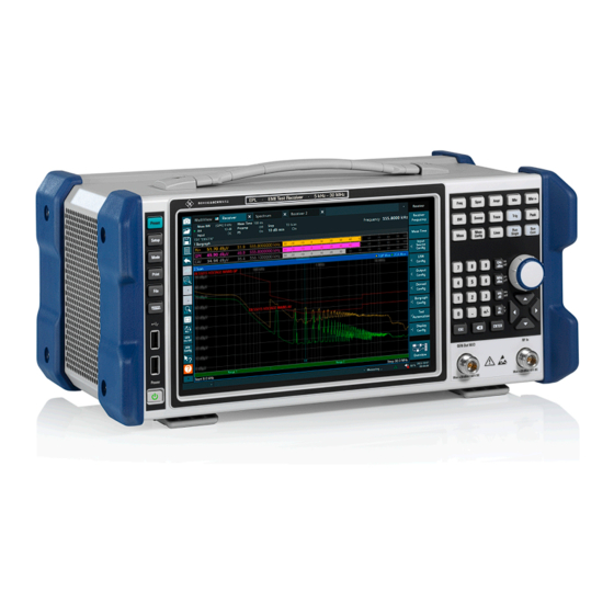
- Page 34 ® Instrument tour R&S EPL1000 Front panel view Instrument tour Front panel view This chapter describes the front panel, including all function keys and connectors. Figure 5-1: Front panel view of R&S EPL1000 1 = Power key 2 = USB (2.0) connectors 3 = System keys 4 = Touchscreen 5 = Function keys...
- Page 35 ® Instrument tour R&S EPL1000 Front panel view ing an alternative means of user interaction for quick and easy handling of the instrument. Figure 5-2: Touchscreen elements 1 = Toolbar with standard application functions, e.g. print, save/open file etc. 2 = Tabs for individual channel setups 3 = Channel setup bar for firmware and measurement settings 4 = Measurement results area 5 = Window title bar with diagram-specific (trace) information...
- Page 36 ® Instrument tour R&S EPL1000 Front panel view ● Zooming into a diagram ● Selecting a new evaluation method ● Scrolling through a result list or table ● Saving or printing results and settings To imitate a right-click by mouse using the touchscreen, for example to open a context-sensitive menu for a specific item, press the screen for about 1 second.
- Page 37 ® Instrument tour R&S EPL1000 Front panel view Table 5-1: System keys System key Assigned functions [Preset] Resets the instrument to the default state. [Setup] Provides basic instrument configuration functions, e.g.: ● Reference frequency (external/internal) ● Date, time, display configuration ●...
- Page 38 ® Instrument tour R&S EPL1000 Front panel view Function key Assigned functions [Sweep] Provides functionality to configure the measurement, for exam- ple: ● the measurement mode (single or continuous measure- ments) ● the measurement time [Trace] Configures the graphical analysis of the measurement data [Meas] Provides the measurement functions [Meas Config]...
- Page 39 ® Instrument tour R&S EPL1000 Front panel view Type of key Description Unit keys Adds the selected unit to the entered numeric value and com- plete the entry. (GHz/-dBm MHz/dBm, kHz/dB, Hz/dB etc.) For level entries (e.g. in dB) or dimensionless values, all units have the value "1"...
- Page 40 ® Instrument tour R&S EPL1000 Front panel view ● In lists: toggles between entries ● For markers, limit lines, and other graphical elements on the screen: moves their position ● For active scroll bars: moves the scroll bar vertically ● For dialog boxes: Same effect as the Enter key when pressed 5.1.7.2 Navigation keys The navigation keys can be used alternatively to the rotary knob to navigate...
- Page 41 ® Instrument tour R&S EPL1000 Rear panel view 5.1.9 GEN output 50 Ohm Provides signal output from the (optional) internal generator (requires Internal Generator option R&S EPL1-B9 or option R&S EPL1-B91). Output levels range from -60 dBm to +10 dBm, with a resolution of 0.1 dB. For details, see the data sheet.
- Page 42 ® Instrument tour R&S EPL1000 Rear panel view 13 = "USB" (3.0) connectors 14 = "LAN" connector 15 = "DisplayPort" connector for external display The meanings of the labels on the R&S EPL1000 are described in Chap- ter 1.2, "Labels on R&S EPL1000", on page 9.
- Page 43 ® Instrument tour R&S EPL1000 Rear panel view Description Plus Ground Not used If you use an external power supply unit to supply safety extra-low DC voltage (SELV) to the instrument, be sure to meet the requirements for reinforced/double insulation in accordance with DIN/EN/IEC 61010 (UL 3111, CSA C22.2 No. 1010.1) or DIN/EN/IEC 60950 (UL 1950, CSA C22.2 No.
- Page 44 ® Instrument tour R&S EPL1000 Rear panel view Connector Reference signal Usage Ref. In 10 MHz To provide an external reference signal on the R&S EPL1000. 10 dBm Ref. Out 10 MHz To provide the internal reference signal from the R&S EPL1000 to another device continuously.
- Page 45 ® Instrument tour R&S EPL1000 Rear panel view 5.2.8 Aux. Port A 25-pole SUB-D male connector used as an input and output for low-voltage TTL control signals (max. 5 V). Short-circuit hazard Always observe the designated pin assignment. A short-circuit can damage the port.
- Page 46 ® Instrument tour R&S EPL1000 Rear panel view Signal Description Ground 24 to 25 not used for spectrum analysis 5.2.9 Headphones connector The R&S EPL1000 provides demodulators for AM and FM signals, which can be routed to the headphone connector. With headphones or an external loudspeaker connected to the 3.5 mm headphone socket, the displayed signal can be identi- fied acoustically.
- Page 47 ® Instrument tour R&S EPL1000 Rear panel view For details, see Chapter 4.14, "Considerations for test setup", on page 32. 5.2.14 Device ID The unique device identifier is provided as a barcode sticker on the rear panel of the R&S EPL1000. It consists of the device order number and a serial number.
- Page 48 ® Operating the instrument R&S EPL1000 Understanding the display information Operating the instrument This chapter provides an overview on how to work with the R&S EPL1000. Remote control In addition to working with the R&S EPL1000 interactively, located directly at the instrument, it is also possible to operate and control it from a remote PC.
- Page 49 ® Operating the instrument R&S EPL1000 Understanding the display information 1 = Channel bar: shows firmware and measurement settings 2 = Window title bar: shows diagram-specific (trace) information 3 = Diagram area: contains the measurement results and other information related to the mea- surement (marker etc.) 4 = Diagram footer: shows diagram-specific information, depending on measurement application 5 = Instrument status bar: shows error messages, measurement progress, date/time etc.
- Page 50 ® Operating the instrument R&S EPL1000 Understanding the display information If many tabs are open, you can also select the tab selection list icon at the right end of the channel bar and select the channel you want to see. MultiView tab An additional tab labeled "MultiView"...
- Page 51 ® Operating the instrument R&S EPL1000 Understanding the display information The exclamation mark icon ( ) indicates that an error or warning is available for that measurement channel. This is particularly useful if the MultiView tab is dis- played. icon indicates the currently active channel during an automatic measure- ment sequence (sequencer functionality).
- Page 52 ® Operating the instrument R&S EPL1000 Understanding the display information Label Information "SGL" Indicates the progress of single measure- ments. The first number is the current measurement. The second number is the total number of measurements. Only displayed for single measurements and if the scan count is greater than 1.
- Page 53 ® Operating the instrument R&S EPL1000 Understanding the display information valid and the measurement is correct. A red bullet indicates an invalid setting that does not provide useful results. 6.1.2 Window title bar Each channel in the R&S EPL1000 display can contain several windows. Each window can display either a graph or a table as a result of the channel measure- ment.
- Page 54 ® Operating the instrument R&S EPL1000 Understanding the display information Marker information in marker table In addition to the marker information displayed within the diagram grid, a separate marker table can be displayed beneath the diagram. This table provides the fol- lowing information for all active markers: Label Information...
- Page 55 ® Operating the instrument R&S EPL1000 Understanding the display information In the MultiView tab, the status bar always displays the information for the cur- rently selected measurement. The following information is displayed: Instrument status The instrument is configured for operation with an external reference. Battery loading status Date and time The date and time settings of the instrument are displayed in the status bar.
- Page 56 ® Operating the instrument R&S EPL1000 Accessing the functionality If any error information is available for a channel setup, an exclamation mark is displayed next to the channel setup name ( ). This is particularly useful when the MultiView tab is displayed, as the status bar in the Multi- View tab always displays the information for the currently selected channel setup only.
- Page 57 ® Operating the instrument R&S EPL1000 Accessing the functionality You can hide the toolbar display, e.g. when using remote control, to enlarge the display area for the measurement results ( "Setup" > "Display" > "Dis- played Items" ). See the R&S EPL1000 User Manual. Print immediately....................
- Page 58 ® Operating the instrument R&S EPL1000 Accessing the functionality The undo function is useful, for example, if you are performing a zero span mea- surement with several markers and a limit line defined and accidentally select a different measurement. In this case, many settings would be lost. However, if you press [UNDO] immediately afterwards, the previous status is retrieved, i.e.
- Page 59 ® Operating the instrument R&S EPL1000 Accessing the functionality Chapter 6.5, "Getting help", on page 66 Disconnect RF2 RF2 input off: Signal applied to the RF2 input is not measured (instead the signal path of the calibration signal is used). Frequency lock Frequency does not change when you turn the rotary knob.
- Page 60 ® Operating the instrument R&S EPL1000 Accessing the functionality You can hide the softkey display, e.g. when using remote control, to enlarge the display area for the measurement results ( "Setup" > "Display" > "Dis- played Items" ). See the User Manual for details. 6.2.3 Context menus Several items in the diagram area have context menus (for example markers,...
- Page 61 ® Operating the instrument R&S EPL1000 Entering data The on-screen keyboard display can be switched on and off as desired using the "On-Screen Keyboard" function key beneath the screen. When you press this key, the display switches between the following options: ●...
- Page 62 ® Operating the instrument R&S EPL1000 Entering data Transparent dialog boxes You can change the transparency of the dialog boxes to see the results in the windows behind the dialog box. Thus, you can see the effects that the changes you make to the settings have on the results immediately. To change the transparency, select the transparency icon at the top of the dialog box.
- Page 63 ® Operating the instrument R&S EPL1000 Touchscreen gestures Correcting an entry 1. Using the arrow keys, move the cursor to the right of the entry you want to delete. 2. Press the [Backspace] key. The entry to the left of the cursor is deleted. 3.
- Page 64 ® Operating the instrument R&S EPL1000 Touchscreen gestures Double-tapping Tap the screen twice, in quick succession. Double-tap a diagram or the window title bar to maximize a window in the display, or to restore the original size. Dragging Move your finger from one position to another on the display, keeping your finger on the display the whole time.
- Page 65 ® Operating the instrument R&S EPL1000 Touchscreen gestures Figure 6-3: Pinching Figure 6-4: Spreading Touch gestures in diagrams change measurement settings When you change the display using touch gestures, the corresponding mea- surement settings are adapted. This is different to selecting an area on the screen in zoom mode, where merely the resolution of the displayed trace points is changed temporarily (graphical zoom).
- Page 66 ® Operating the instrument R&S EPL1000 Getting help Mouse operation Touch operation Drag-&-drop (= click and hold, then drag and Touch, then drag and release release) n.a. (Change hardware settings) Spread and pinch two fingers Mouse wheel to scroll up or down Swipe Dragging scrollbars to scroll up or down, left or Swipe...
- Page 67 ® Operating the instrument R&S EPL1000 Getting help The "Help" dialog box "View" tab is displayed. A topic containing information about the focused screen element is displayed. If no context-specific help topic is available, a more general topic or the "Con- tent"...
- Page 68 ® Customer support R&S EPL1000 Collecting information for support Customer support Collecting information for support If problems occur, the instrument generates error messages which in most cases will be sufficient for you to detect the cause of an error and find a remedy. Error messages are described in the "Troubleshooting"...
- Page 69 ® Customer support R&S EPL1000 Collecting information for support To collect the support information 1. Press the [Setup] key. 2. Select "Service" > "R&S Support" and then "Create R&S Support Informa- tion" . The file is stored as C:\Users\Public\Documents\Rohde-Schwarz\Analyzer\user\ <inst_model>_<serial-no>_<date_and_time>.zip For example C:\ProgramData\Rohde-Schwarz\ZNL-FPL\user\EPL1000__20220103_145113 To create windows event log files...
- Page 70 ® Customer support R&S EPL1000 Contacting customer support Figure 7-1: Event Viewer 5. Enter a file name and select "Save" Collect the error information and attach it to an email in which you describe the problem. Send the email to the customer support address for your region as listed Chapter 7.2, "Contacting customer support", on page 70.
- Page 71 ® Customer support R&S EPL1000 Contacting customer support Contact information Contact our customer support center at www.rohde-schwarz.com/support, or fol- low this QR code: Figure 7-2: QR code to the Rohde & Schwarz support page Getting Started 1179.5676.02 ─ 01...
- Page 72 ® Index R&S EPL1000 Index Symbols Diagram area Status display ........54 75 Ω (channel bar) ........52 Trace information ........ 53 Diagram footer .........54 Dialog boxes Alphanumeric parameters ....... 62 Slider ...........62 Application cards ........13 Transparency ........62 Application notes ........13 Display APX (channel bar) ........
- Page 73 ® Index R&S EPL1000 NOR (channel bar) ........52 Numeric parameters ........ 62 Headphones Connector ........... 46 Help ............66 On-screen keyboard ......60, 62 Online help Working with ........66 IF/VIDEO/DEMOD Out (channel bar) ........51 Connector ........... 44 Input (channel bar) ........
- Page 74 ® Index R&S EPL1000 Tabs MultiTab ..........50 Switching ..........49 Tdf (channel bar) ........52 Technical support ........68 Touchscreen Overview ..........34 Trace information ........53 Detector type ........53 Trace number ........53 Window title bar ........53 TRG (channel bar) ........52 Trigger In Connector ...........
Need help?
Do you have a question about the R&S EPL1000 and is the answer not in the manual?
Questions and answers