Table of Contents
Advertisement
Quick Links
Advertisement
Table of Contents

Related Manuals for Rohde & Schwarz R&S ESW


Summary of Contents for Rohde & Schwarz R&S ESW
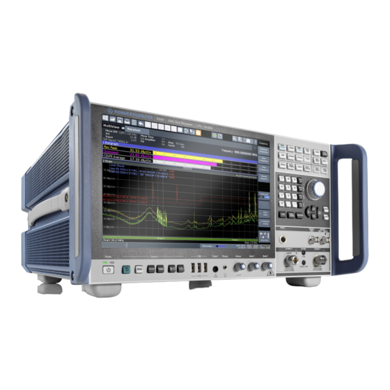
- Page 1 ® R&S EMI Test Receiver Getting Started (=LaF2) 1328492202 Version 09...
- Page 2 ® This manual describes the following R&S ESW models: ● R&S ® ESW8 (1328.4100K08) ● R&S ® ESW8 (1328.4100K09) ● R&S ® ESW26 (1328.4100K26) ● R&S ® ESW26 (1328.4100K27) ● R&S ® ESW44 (1328.4100K44) ● R&S ® ESW44 (1328.4100K45) The contents of this manual correspond to firmware version 2.10 and higher. ©...
-
Page 3: Table Of Contents
® Contents R&S Contents 1 Safety and Regulatory Information........7 1.1 Safety Instructions................7 1.2 Warning Messages in the Documentation........12 1.3 Korea Certification Class B..............13 2 Documentation Overview............14 2.1 Getting Started Manual...............14 2.2 User Manuals and Help..............14 2.3 Service Manual..................15 2.4 Instrument Security Procedures............ - Page 4 ® Contents R&S 4.5 Connecting the AC Power..............22 4.6 Switching the Instrument On and Off..........23 4.7 Connecting to LAN................24 4.8 Connecting a Keyboard..............26 4.9 Connecting an External Monitor............26 4.10 Windows Operating System...............28 4.11 Logging On..................30 4.12 Checking the Supplied Options............32 4.13 Performing a Self-Alignment.............
- Page 5 ® Contents R&S 5.2.2 AC Power Supply Connection and Main Power Switch......49 5.2.3 Display Port and DVI................50 5.2.4 LAN Connector..................50 5.2.5 USB Ports..................... 50 5.2.6 IF / Video / Demod Output..............50 5.2.7 Sync Trigger Input and Output.............. 51 5.2.8 GPIB Interface..................
- Page 6 ® Contents R&S 6.4 Entering Data..................69 6.4.1 Entering Numeric Parameters...............70 6.4.2 Entering Alphanumeric Parameters............70 6.5 Touchscreen Gestures............... 72 6.6 Displaying Results................76 6.6.1 Activating and Deactivating Channels..........76 6.6.2 Laying out the Result Display with the SmartGrid.........78 6.6.3 Changing the Size of Windows............. 82 6.6.4 Switching Between a Split and Maximized Window Display....83 6.6.5 Changing the Display................84 6.7 Getting Help..................84...
-
Page 7: Safety And Regulatory Information
® Safety and Regulatory Information R&S Safety Instructions Safety and Regulatory Information The product documentation helps you use the product safely and efficiently. Fol- low the instructions provided here and in the Chapter 1.1, "Safety Instructions", on page 7. Intended use The product is intended for the development, production and verification of elec- tronic components and devices in industrial, administrative, and laboratory envi- ronments. - Page 8 ® Safety and Regulatory Information R&S Safety Instructions Never open the casing of the product. Only service personnel authorized by Rohde & Schwarz are allowed to repair the product. If any part of the product is damaged or broken, stop using the product. Contact Rohde & Schwarz customer service at http://www.customersupport.rohde-schwarz.com.
- Page 9 ® Safety and Regulatory Information R&S Safety Instructions uct is moved without lifting it. The foldable feet are designed to carry the weight of the product, but not an extra load. If stacking is possible, keep in mind that a stack of products can fall over and cause injury.
- Page 10 ® Safety and Regulatory Information R&S Safety Instructions these requirements, provide an easily accessible circuit breaker at the system level. Using laser products Lasers are classified according to their potential risk. If exposure to the laser beam is possible, the product is labeled as shown in the table explaining the safety labels.
- Page 11 ® Safety and Regulatory Information R&S Safety Instructions ● Only use the appropriate Rohde & Schwarz charger to charge the batteries. If the batteries are improperly charged, there is a risk of explosion. For charging and discharging temperature ranges, see the product documentation. ●...
-
Page 12: Warning Messages In The Documentation
® Safety and Regulatory Information R&S Warning Messages in the Documentation Electrical hazard Indicates live parts. Risk of electric shock, fire, personal injury or even death. Hot surface Do not touch. Risk of skin burns. Risk of fire. Protective conductor terminal Connect this terminal to a grounded external conductor or to protective ground. -
Page 13: Korea Certification Class B
® Safety and Regulatory Information R&S Korea Certification Class B Korea Certification Class B 이 기기는 가정용(B급) 전자파 적합기기로서 주로 가정에서 사용하는 것을 목적으 로 하며, 모든 지역에서 사용할 수 있습니다. Getting Started 1328.4922.02 ─ 09... -
Page 14: Documentation Overview
® Documentation Overview R&S User Manuals and Help Documentation Overview This section provides an overview of the R&S ESW user documentation. You find it on the product page at: www.rohde-schwarz.com/manual/esw Getting Started Manual Introduces the R&S ESW and describes how to set up and start working with the product. -
Page 15: Service Manual
® Documentation Overview R&S Data Sheets and Brochures Service Manual Describes the performance test for checking the rated specifications, module replacement and repair, firmware update, troubleshooting and fault elimination, and contains mechanical drawings and spare part lists. The service manual is available for download for registered users on the global Rohde &... -
Page 16: Release Notes And Open Source Acknowledgment (Osa)
® Documentation Overview R&S Application Notes, Application Cards, White Papers, etc. Release Notes and Open Source Acknowledg- ment (OSA) The release notes list new features, improvements and known issues of the cur- rent firmware version, and describe the firmware installation. The open source acknowledgment document provides verbatim license texts of the used open source software. -
Page 17: Conventions Used In The Documentation
® Conventions Used in the Documentation R&S Conventions for Procedure Descriptions Conventions Used in the Documentation Typographical Conventions The following text markers are used throughout this documentation: Convention Description "Graphical user interface All names of graphical user interface elements on the screen, elements"... -
Page 18: Notes On Screenshots
® Conventions Used in the Documentation R&S Notes on Screenshots Notes on Screenshots When describing the functions of the product, we use sample screenshots. These screenshots are meant to illustrate as many as possible of the provided functions and possible interdependencies between parameters. The shown values may not represent realistic usage scenarios. -
Page 19: Preparing For Use
® Preparing for Use R&S Unpacking and Checking Preparing for Use Here, you can find basic information about setting up the instrument for the first time. ● Lifting and Carrying..................19 ● Unpacking and Checking................19 ● Choosing the Operating Site................ -
Page 20: Choosing The Operating Site
® Preparing for Use R&S Setting Up the Product 4. Check the equipment for damage. If the delivery is incomplete or equipment is damaged, contact Rohde & Schwarz. Choosing the Operating Site Specific operating conditions ensure proper operation and avoid damage to the product and connected devices. -
Page 21: Placing The Product On A Bench Top
® Preparing for Use R&S Setting Up the Product 4.4.1 Placing the Product on a Bench Top To place the product on a bench top 1. Place the product on a stable, flat and level surface. Ensure that the surface can support the weight of the product. -
Page 22: Mounting The R&S Esw In A Rack
® Preparing for Use R&S Connecting the AC Power 4.4.2 Mounting the R&S ESW in a Rack To prepare the rack 1. Observe the requirements and instructions in "Setting up the product" on page 8. 2. NOTICE! Insufficient airflow can cause overheating and damage the product. Design and implement an efficient ventilation concept for the rack. -
Page 23: Switching The Instrument On And Off
® Preparing for Use R&S Switching the Instrument On and Off The R&S ESW can be used with different AC power voltages and adapts itself automatically to it. Refer to the datasheet for the requirements of voltage and fre- quency. For safety information, see "Connecting to power"... -
Page 24: Connecting To Lan
® Preparing for Use R&S Connecting to LAN 2. Press the Power key. Chapter 5.1.2, "Power Key", on page 40. The LED changes to green. The R&S ESW boots. After booting, the instrument is ready for operation. To shut down the product The product is in the ready state. - Page 25 ® Preparing for Use R&S Connecting to LAN ● To access or control the measurement from a remote computer using the "Remote Desktop" application (or a similar tool) ● To connect external network devices (e.g. printers) ● To transfer data from a remote computer and back, e.g. using network folders Network environment Before connecting the product to a local area network (LAN), consider the follow- ing:...
-
Page 26: Connecting A Keyboard
® Preparing for Use R&S Connecting an External Monitor For more information on LAN configuration, see the R&S ESW user manual. Connecting a Keyboard The keyboard is detected automatically when it is connected. The default input language is English – US. However, you can also connect foreign language keyboards;... - Page 27 ® Preparing for Use R&S Connecting an External Monitor Screen resolution and format The touchscreen of the R&S ESW is calibrated for a 16:10 format. If you connect a monitor or projector using a different format (e.g. 4:3), the calibra- tion is not correct and the screen does not react to your touch actions prop- erly.
-
Page 28: Windows Operating System
® Preparing for Use R&S Windows Operating System 5. Select the instrument for display: ● "Display 1" : internal monitor only ● "Display 2" : external monitor only ● "Duplicate" : both internal and external monitor 6. Tap "Apply" to try out the settings before they are accepted permanently, then you can easily return to the previous settings, if necessary. - Page 29 ® Preparing for Use R&S Windows Operating System Tested software The drivers and programs used on the instrument under Microsoft Windows are adapted to the instrument. Only install update software released by Rohde & Schwarz to modify existing instrument software. You can install additional software on the instrument;...
-
Page 30: Logging On
® Preparing for Use R&S Logging On To access the "Start" menu The Windows "Start" menu provides access to the Microsoft Windows functional- ity and installed programs. ► Select the "Windows" icon in the toolbar, or press the "Windows" key or the [CTRL + ESC] key combination on the (external) keyboard. - Page 31 ® Preparing for Use R&S Logging On Passwords Note that the default passwords are very weak, and it is recommended that you change the password for all users after initial login. An administrator can change the password in Microsoft Windows for any user at any time via "Start > Settings >...
-
Page 32: Checking The Supplied Options
® Preparing for Use R&S Checking the Supplied Options Switching users when using the auto-login function Which user account is used is defined during login. If auto-login is active, the login window is not displayed. However, you can switch the user account to be used even when the auto-login function is active. -
Page 33: Performing A Self-Alignment
® Preparing for Use R&S Considerations for Test Setup 4.13 Performing a Self-Alignment When strong temperature changes occur in the environment of the R&S ESW, or after updating the firmware, you have to perform a self-alignment to align the data to a reference source. -
Page 34: Protecting Data Using The Secure User Mode
® Preparing for Use R&S Protecting Data Using the Secure User Mode To suppress electromagnetic radiation during operation: ● Use high-quality shielded cables, for example, double-shielded RF and LAN cables. ● Always terminate open cable ends. ● Ensure that connected external devices comply with EMC regulations. Preventing electrostatic discharge (ESD) Electrostatic discharge is most likely to occur when you connect or disconnect a DUT. - Page 35 ® Preparing for Use R&S Protecting Data Using the Secure User Mode ● Firmware shutdown files containing information on last instrument state ● Self-alignment data ● General instrument settings such as the IP address ● Measurement settings ● User data created during operation ●...
- Page 36 ® Preparing for Use R&S Protecting Data Using the Secure User Mode ● Activating a new option key Furthermore, since the "SecureUser" used in secure user mode does not have administrator rights, administrative tasks such as LAN configuration and some general instrument settings are not available.
- Page 37 ® Preparing for Use R&S Protecting Data Using the Secure User Mode softkey > "Config" tab > "Secure User Mode": "ON", see the R&S ESW user man- ual). Remote control Initially after installation of the R&S ESW-K33 option, secure user mode must be enabled manually once before remote control is possible.
-
Page 38: Instrument Tour
® Instrument Tour R&S The Front Panel Instrument Tour On the instrument tour, you can learn about the different control elements and connectors on the front and back panel of the R&S ESW. The Front Panel The front panel contains the main control elements of the R&S ESW in addition to various connectors as shown in Figure 5-1. -
Page 39: Display (Touchscreen)
® Instrument Tour R&S The Front Panel 11 = Headphone jack 12 = Probe 1 power connector 13 = USB ports 14 = System control keys 15 = Power key 5.1.1 Display (Touchscreen) The touchscreen on the front panel of the R&S ESW displays the measurement results. -
Page 40: Power Key
® Instrument Tour R&S The Front Panel mouse pointer can also be tapped on the screen to trigger the same behavior, and vice versa. Using the touchscreen, the following tasks (among others) can be performed by the tap of your finger: ●... -
Page 41: Usb Ports
® Instrument Tour R&S The Front Panel Provides functionality to configure basic instrument characteristics, for example: ● the LAN connection ● the date and time ● the display configuration ● the reference frequency ● firmware update and application installation ● service functions ●... -
Page 42: Headphone Jack And Volume Control
® Instrument Tour R&S The Front Panel 5.1.6 Headphone Jack and Volume Control The female headphone jack allows you to connect headphones (or external speakers) with a miniature jack plug. You can control the output voltage with the volume control next to the headphone jack. -
Page 43: Trigger Input And Output
® Instrument Tour R&S The Front Panel levels smaller than 10 dB at RF Input 2 are only possible when the pulse limiter is not active (refer to the User Manual for more information). Risk of instrument damage Do not overload the RF input. For maximum allowed values, see the data sheet. -
Page 44: 5.1.10 Navigation Controls
® Instrument Tour R&S The Front Panel 5.1.10 Navigation Controls The navigation controls include a rotary knob, navigation keys, and Undo / Redo keys. They allow you to navigate within the display or within dialog boxes. Navigating in tables The easiest way to navigate within tables (both in result tables and configu- ration tables) is to scroll through the entries with your finger on the touch- screen. -
Page 45: Keypad
® Instrument Tour R&S The Front Panel Arrow Left/Arrow Right Keys The <arrow left> or <arrow right> keys do the following: ● In an alphanumeric edit dialog box, move the cursor. ● In a list, scroll forward and backward through the list entries. ●... -
Page 46: 5.1.12 The Function Keys
® Instrument Tour R&S The Front Panel Type of key Description Unit keys (GHz/-dBm MHz/ Adds the selected unit to the entered numeric value and com- dBm, kHz/dB and Hz/dB) plete the entry. For level entries (e.g. in dB) or dimensionless values, all units have the value "1"... - Page 47 ® Instrument Tour R&S The Front Panel Provides functionality to automatically define various parameters like the level or frequency. Provides functionality to define various filter bandwidths. Provides functionality to configure the measurement, for example: ● the measurement mode (single or continuous measurements) ●...
-
Page 48: The Rear Panel
® Instrument Tour R&S The Rear Panel Provides functionality to control display and limit lines. Provides functionality to configure inputs and outputs. Starts a measurement in single measurement mode. Starts a measurement in continuous measurement mode. The Rear Panel The rear panel contains various connectors as shown in Figure 5-2. -
Page 49: Removable Hard Disk
® Instrument Tour R&S The Rear Panel 7 = GPIB interface 8 = AUX port 9 = REF inputs and outputs 10 = Trigger in- and output 11 = IF / Video / Demod output 12 = Instrument Serial Number 13 = Ground connector ●... -
Page 50: Display Port And Dvi
® Instrument Tour R&S The Rear Panel For details, refer to "Connecting to power" on page 9 and Chapter 4.5, "Connect- ing the AC Power", on page 22. 5.2.3 Display Port and DVI You can connect an external monitor or other display device to the R&S ESW to provide an enlarged display. -
Page 51: Sync Trigger Input And Output
® Instrument Tour R&S The Rear Panel Details about configuring the output type and characteristics are part of the user manual. 5.2.7 Sync Trigger Input and Output The "Sync Trigger Input / Output" connectors allow you to synchronize several devices (for example two R&S ESWs) with respect to the trigger signal, but also the reference frequency. -
Page 52: Ocxo (Optional)
® Instrument Tour R&S The Rear Panel For details on connecting an external generator, see the "External Generator Control" section of the R&S ESW User Manual. 5.2.11 OCXO (Optional) This optional OCXO generates a 10 MHz reference signal with a very precise fre- quency. -
Page 53: 5.2.13 Labels On R&S Esw
® Instrument Tour R&S The Rear Panel Connector Reference signal Usage REF OUTPUT 100 MHz To provide a 100 MHz reference signal from the R&S ESW to another device. 6 dBm REF OUTPUT 640 MHz To provide a 640 MHz reference signal from the R&S ESW to another device. - Page 54 ® Instrument Tour R&S The Rear Panel The serial number is used to define the default instrument name, which is: <Type><variant>-<serial_number> For example, ESW26-123456. The instrument name is required to establish a connection to the instrument in a LAN. Getting Started 1328.4922.02 ─ 09...
-
Page 55: Operating The Instrument
® Operating the Instrument R&S Understanding the Display Information Operating the Instrument The following topics provide an overview on how to work with the R&S ESW. They describe what kind of information is displayed in the diagram area, how to interact with the R&S ESW, and how to use the online help. - Page 56 ® Operating the Instrument R&S Understanding the Display Information 1 = Channel bar: shows firmware and measurement settings 2 = Window title bar: shows diagram-specific (trace) information 3 = Diagram area: contains the measurement results and other information related to the mea- surement (marker etc.) 4 = Diagram footer: shows diagram-specific information, depending on measurement application 5 = Instrument status bar: shows error messages, measurement progress, date/time etc.
-
Page 57: Channel Bar
® Operating the Instrument R&S Understanding the Display Information 6.1.1 Channel Bar Using the R&S ESW you can handle several different measurement tasks (chan- nels) at the same time (although they can only be performed asynchronously). For each channel, a separate tab is displayed on the screen. To switch from one channel display to another, simply select the corresponding tab. - Page 58 ® Operating the Instrument R&S Understanding the Display Information icon indicates the currently active channel during an automatic measure- ment sequence (sequencer functionality). Beneath the channel name, information about channel-specific settings for the measurement is displayed in the channel bar. Channel information varies depending on the active application.
-
Page 59: Window Title Bar
® Operating the Instrument R&S Understanding the Display Information Label Information "LISN" Currently selected LISN and LISN phase. For R&S ENV216, it also shows the state of the highpass filter. Only displayed when a LISN is included in the measurement. "SGL"... - Page 60 ® Operating the Instrument R&S Understanding the Display Information Trace information in window title bar Information on the displayed traces is indicated in the window title bar. Trace number Trace mode Trace color Detector Trace color Color of trace display in diagram Trace no.
-
Page 61: Marker Information
® Operating the Instrument R&S Understanding the Display Information Trace Mode Abbreviation of the trace mode: ● Clrw Clear Write: Shows the currently measured values. ● Max Hold: Shows the maximum values that have been measured. ● Min Hold: Shows the minimum values that have been measured. ●... -
Page 62: Frequency And Span Information In Diagram Footer
® Operating the Instrument R&S Understanding the Display Information Label Information "X-value" x-value of the marker "Y-value" y-value of the marker 6.1.4 Frequency and Span Information in Diagram Footer The information in the diagram footer (beneath the diagram) depends on the cur- rent application. -
Page 63: Error Information
® Operating the Instrument R&S Understanding the Display Information Progress The status of the current operation is displayed in the status bar. In the MultiView tab, the progress bar indicates the status of the currently selected measurement, not the measurement currently being performed by a sequencer, for example. -
Page 64: Accessing Functions
® Operating the Instrument R&S Accessing Functions Table 6-2: Status bar information - color coding Color Type Description Error An error occurred at the start or during a measurement, e.g. due to missing data or wrong settings, so that the measurement cannot be started or completed correctly. -
Page 65: Toolbar
® Operating the Instrument R&S Accessing Functions ● Icons on the tool bar in the touchscreen ● Displayed setting on the touchscreen ● Toolbar......................65 ● Softkeys......................67 ● Context Menus....................67 ● On-screen Keyboard..................68 6.2.1 Toolbar The icons in the toolbar provide access to general functions. You can hide the toolbar display, for example when using remote control, in order to enlarge the display area for the measurement results ("Setup >... - Page 66 ® Operating the Instrument R&S Accessing Functions Measurement zoom: applies to the next display you select; Displays a dotted rectangle in the diagram that can be expanded to define the zoom area; the selected diagram is replaced by a new diagram with adapted measurement settings which displays the selected extract of the trace.
-
Page 67: Softkeys
® Operating the Instrument R&S Accessing Functions RF input off: Signal applied to the RF input is not measured (instead the sig- nal path of the calibration signal is used). Note that this icon is only visible if you deliberately turn it on. ([SETUP] >... -
Page 68: On-Screen Keyboard
® Operating the Instrument R&S Accessing Functions it for about 1 second), a menu is displayed which contains the same functions as the corresponding softkey. This is useful, for example, when the softkey display is hidden. 6.2.4 On-screen Keyboard The on-screen keyboard is an additional means of interacting with the instrument without having to connect an external keyboard. -
Page 69: Changing The Focus
® Operating the Instrument R&S Entering Data ● Keyboard displayed at the top of the screen ● Keyboard displayed at the bottom of the screen ● No keyboard displayed You can use the TAB key on the on-screen keyboard to move the focus from one field to another in dialog boxes. -
Page 70: Entering Numeric Parameters
® Operating the Instrument R&S Entering Data Transparent dialog boxes You can change the transparency of the dialog boxes to see the results in the windows behind the dialog box. Thus, you can see the effects that the changes you make to the settings have on the results immediately. To change the transparency, select the transparency icon at the top of the dialog box. - Page 71 ® Operating the Instrument R&S Entering Data Alternatively, you can use the keypad. Every alphanumeric key represents sev- eral characters and one number. The decimal point key (.) represents special characters, and the sign key (-) toggles between capital and small letters. For the assignment, refer to Table 6-3.
-
Page 72: Touchscreen Gestures
® Operating the Instrument R&S Touchscreen Gestures To complete the entry ► Press the [ENTER] key or the rotary knob. To abort the entry ► Press the [ESC] key. The dialog box is closed without changing the settings. Table 6-3: Keys for alphanumeric parameters Key name Series of (special) characters and number provided (upper inscription) - Page 73 ® Operating the Instrument R&S Touchscreen Gestures You can tap most elements on the screen; in particular, any elements you can also click on with a mouse pointer. Figure 6-1: Tapping Double-tapping Tap the screen twice, in quick succession. Double-tap a diagram or the window title bar to maximize a window in the display, or to restore the original size.
- Page 74 ® Operating the Instrument R&S Touchscreen Gestures You can pinch or spread your fingers vertically, horizontally, or diagonally. The direction in which you move your fingers determines which dimension of the dis- play is changed. Figure 6-3: Pinching Figure 6-4: Spreading Touch gestures in diagrams change measurement settings When you change the display using touch gestures, the corresponding mea- surement settings are adapted.
- Page 75 ® Operating the Instrument R&S Touchscreen Gestures Mouse vs. touch actions Any user interface elements that react to actions by a mouse pointer also react to finger gestures on the screen, and vice versa. The following touch actions corre- spond to mouse actions: Table 6-4: Correlation of mouse and touch actions Mouse operation Touch operation...
-
Page 76: Displaying Results
® Operating the Instrument R&S Displaying Results Displaying Results The R&S ESW provides several instrument applications for different analysis tasks and different types of signals, for example the Receiver application, the Spectrum application or the I/Q Analyzer. For each application, a new measure- ment channel is created and displayed in a separate tab on the screen. - Page 77 ® Operating the Instrument R&S Displaying Results To start a new channel 1. Select the [Mode] key. 2. In the "Mode" dialog box, select the required application on the "New Chan- nel" tab. A new tab is displayed for the new channel. To change the application in an active channel 1.
-
Page 78: Laying Out The Result Display With The Smartgrid
® Operating the Instrument R&S Displaying Results Select the "Close" icon on the tab of the measurement channel. The tab is closed, any running measurements are aborted, and all results for that channel are deleted. 6.6.2 Laying out the Result Display with the SmartGrid Measurement results can be evaluated in many different ways, for example graphically, as summary tables, statistical evaluations etc. -
Page 79: Background Information: The Smartgrid Principle
® Operating the Instrument R&S Displaying Results ● Background Information: The SmartGrid Principle..........79 ● How to Activate SmartGrid Mode..............80 ● How to Add a New Result Window..............81 ● How to Close a Result Window...............81 ● How to Arrange the Result Windows.............. -
Page 80: How To Activate Smartgrid Mode
® Operating the Instrument R&S Displaying Results 6-6). If an existing window would be replaced, the drop area is highlighted in a darker color shade. Positioning the window The screen can be divided into up to four rows. Each row can be split into up to four columns, where each row can have a different number of columns. -
Page 81: How To Add A New Result Window
® Operating the Instrument R&S Displaying Results the SmartGrid mode is deactivated again, the previous softkey menu display is restored. ► To activate SmartGrid mode, do one of the following: ● Select the "SmartGrid" icon from the toolbar. ● Select the "Display Config" button in the configuration "Overview" . ●... -
Page 82: Changing The Size Of Windows
® Operating the Instrument R&S Displaying Results 6.6.2.5 How to Arrange the Result Windows 1. Select an icon from the evaluation bar or the "Move" icon for an existing eval- uation window. 2. Drag the evaluation over the SmartGrid. A blue area shows where the window will be placed. 3. -
Page 83: Switching Between A Split And Maximized Window Display
® Operating the Instrument R&S Displaying Results The splitters are not available in SmartGrid mode. ► To change the size of two neighboring windows, drag the splitter between the windows in either direction. 6.6.4 Switching Between a Split and Maximized Window Dis- play To get an overview of the results, displaying several windows at the same time may be helpful. -
Page 84: Changing The Display
® Operating the Instrument R&S Getting Help Alternatively, double-tap the title bar of a window to maximize it. 6.6.5 Changing the Display The display can be optimized for your individual needs. The following display functions are available and are described in detail in the User Manual. ●... -
Page 85: Remote Control
® Operating the Instrument R&S Remote Control The "Help" dialog box "View" tab is displayed. A topic containing information about the focused screen element is displayed. If no context-specific help topic is available, a more general topic or the "Con- tent"... -
Page 86: Remote Desktop Connection
® Operating the Instrument R&S Remote Control 6.8.1 Remote Desktop Connection Remote Desktop is a Windows application which can be used to access and con- trol the instrument from a remote computer through a LAN connection. While the instrument is in operation, the instrument screen contents are displayed on the remote computer. -
Page 87: Contacting Customer Support
® Contacting Customer Support R&S Contacting Customer Support Technical support – where and when you need it For quick, expert help with any Rohde & Schwarz product, contact our customer support center. A team of highly qualified engineers provides support and works with you to find a solution to your query on any aspect of the operation, program- ming or applications of Rohde &... -
Page 88: Index
® Index R&S Index Symbols Connectors OCXO ..........52 75 Ω (channel bar) ........59 SYNC TRIGGER ........ 51 Trigger Input ........43 Trigger Output ........43 AC (trace information) ......60 USB ............ 41 Alphanumeric parameters ....... 70 Context-sensitive menus ......67 AP (trace information) ...... - Page 89 ® Index R&S External reference Keypad ............ 71 Status message ........62 Key layout ........... 72 Overview ..........45 Firmware updates see User Manual .........19 Focus Configuration - see user Manual ..19 Changing ..........69 Connector ........... 50 Frequency (channel bar) ......59 LISN (channel bar) ........
- Page 90 ® Index R&S Options Saving Secure user mode (K33) .....34 Classified data ........34 Out (channel bar) ........58 Secure user mode Overheating Activating/deactivating ......36 Shutdown ..........24 Background information ...... 34 Passwords .......... 36 Redirecting storage ......34 Restricted operation ......35 Parameters Self-alignment data ......
- Page 91 ® Index R&S Touch-sensitivity De-/activating - see User Manual ..84 Touchscreen Overview ..........39 Trace information ........60 Detector type ........60 Trace number ........60 Window title bar ........60 TRG (channel bar) ........59 Trigger Input ............ 43 Output ..........43 Undo Key ............45 Connector ...........
Need help?
Do you have a question about the R&S ESW and is the answer not in the manual?
Questions and answers