
Related Manuals for Rohde & Schwarz 890 Series


Summary of Contents for Rohde & Schwarz 890 Series
- Page 1 ® R&S Series 890 VLF-HF Receivers ® ® R&S EK895/ R&S EK896 User Manual 6164.0171.02 - 01...
- Page 2 The documentation describes following models: ® R&S EK895 — 6057.8996.xx — SW Version: 04.00 — DSP Version: 02.00 ® R&S EK896 — 6038.2509.xx — SW Version: 04.00 — DSP Version: 02.00 © 03/2010 Rohde & Schwarz GmbH & Co. KG 81671 Munich, Germany Printed in Germany —...
- Page 3 KONFORMITÄTSERKLÄRUNG gemäß dem Gesetz über Funkanlagen und Telekommunikationsendeinrichtungen (FTEG) und der Richtlinie 1999/5/EG (R&TTE) DECLARATION OF CONFORMITY in accordance with the Radio and Telecommunications Terminal Equipment Act (FTEG) and Directive 1999/5/EC (R&TTE Directive) Zertifikat-Nr.: / 2006-77 Certificate No.: Hiermit wird bescheinigt, dass die Funkanlage This is to certify that the radio equipment Gerätetyp Materialnummer...
- Page 5 KONFORMITÄTSERKLÄRUNG gemäß dem Gesetz über Funkanlagen und Telekommunikationsendeinrichtungen (FTEG) und der Richtlinie 1999/5/EG (R&TTE) DECLARATION OF CONFORMITY in accordance with the Radio and Telecommunications Terminal Equipment Act (FTEG) and Directive 1999/5/EC (R&TTE Directive) Anlage zu Zertifikat-Nr.: 2006-77 Enclosure to Certificate No.: Gerätetyp Materialnummer Benennung...
- Page 7 KONFORMITÄTSERKLÄRUNG gemäß dem Gesetz über Funkanlagen und Telekommunikationsendeinrichtungen (FTEG) und der Richtlinie 1999/5/EG (R&TTE) DECLARATION OF CONFORMITY in accordance with the Radio and Telecommunications Terminal Equipment Act (FTEG) and Directive 1999/5/EC (R&TTE Directive) Zertifikat-Nr.: / 2006-37 Certificate No.: Hiermit wird bescheinigt, dass die Funkanlage This is to certify that the radio equipment Gerätetyp Materialnummer...
- Page 9 KONFORMITÄTSERKLÄRUNG gemäß dem Gesetz über Funkanlagen und Telekommunikationsendeinrichtungen (FTEG) und der Richtlinie 1999/5/EG (R&TTE) DECLARATION OF CONFORMITY in accordance with the Radio and Telecommunications Terminal Equipment Act (FTEG) and Directive 1999/5/EC (R&TTE Directive) Anlage zu Zertifikat-Nr.: 2006-37 Enclosure to Certificate No.: Gerätetyp Materialnummer Benennung...
- Page 11 ® ® HF RECEIVERS R&S EK 895 / R&S EK 896 User Manual Notice: ® ® The HF Receivers R&S EK 895 / R&S EK 896 were tested in accordance with ETSI EN 300 373-1 V1.2.1 (2002-10) with following deviations: ETSI EN 300 373-1 / 7.5 Temperature Tests ®...
- Page 13 V L F > H F R E C E I V E R S R & S E K 8 9 5 / R & S E K 8 9 6 User Manual C A U T I O N When switching the VLF>HF Receiver EK 895 on at an ambient temperature of >25!∞C, allow approx.
- Page 15 V L F > H F R E C E I V E R S E K 8 9 5 / E K 8 9 6 User Manual Definitions In the BIT (built>in test) it is checked whether all modules of the basic unit are installed and operative.
- Page 16 V L F > H F R E C E I V E R S E K 8 9 5 / E K 8 9 6 User Manual Visual examination This is a visual inspection of the outer appearance and com> pleteness of a component / module / unit without manual in>...
- Page 17 V L F > H F R E C E I V E R S E K 8 9 5 / E K 8 9 6 User Manual Notices The three different notices used in this User Manual have the following meaning: Note: W A R N I N G This heading is used to draw the reader's atten>...
- Page 19 V L F > H F R E C E I V E R S E K 8 9 5 / E K 8 9 6 User Manual Application User Information Purpose of the Manual This Manual provides all information the operators and service staff need to maintain levels 1 and 2 of repairs.
- Page 21 User Manual VLF > HF RECEIVERS R&S EK 895 R&S EK 896 CHARACTERISTICS Application, Design and Functioning of the VLF>HF Receivers, Design and Functioning of Modules, Technical Data, Explanation of Models PREPARATION FOR USE Safety Notes, Unpacking and Checking, Operating Functions, Installation, Cabling, Cables for Control and Status Data OPERATION Control Unit 2 'LOCAL' (R&S EK 895, = Option 'Control Unit R&S GB 890') or...
-
Page 23: Table Of Contents
V L F > H F R E C E I V E R S R & S E K 8 9 5 / R & S E K 8 9 6 User Manual List of Contents 1. Characteristics Page Application . - Page 24 V L F > H F R E C E I V E R S R & S E K 8 9 5 / R & S E K 8 9 6 User Manual Page 1.3.10 Preselection R&S FK 890H1 (Option) ..... 1.26 1.3.11 BCD Interface R&S GC 890 (Option) .
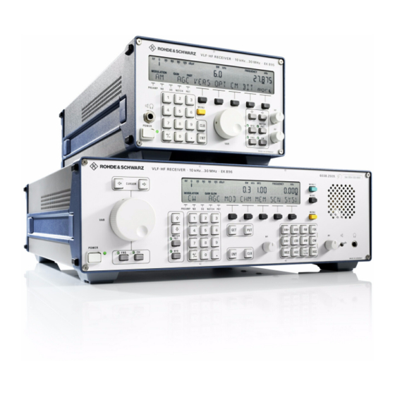
- Page 25 V L F > H F R E C E I V E R S R & S E K 8 9 5 / R & S E K 8 9 6 User Manual List of Figures Fig. Title Page VLF>HF Receivers R&S EK 895 / R&S EK 896 .
- Page 26 V L F > H F R E C E I V E R S R & S E K 8 9 5 / R & S E K 8 9 6 User Manual Appendix Data Sheet ........PD 758.0251.32 Circuit Diagram (R&S EK 895) .
-
Page 27: Application
V L F > H F R E C E I V E R S R & S E K 8 9 5 / R & S E K 8 9 6 User Manual Application Characteristics Application The digital VLF>HF Receiver R&S EK!895 is a The receiver is also suitable for remote control powerful receiver for voice reception and data via a conventional PC or an ASCII terminal. -
Page 28: Design And Functioning
V L F > H F R E C E I V E R S R & S E K 8 9 5 / R & S E K 8 9 6 User Manual Application Design and Functioning 1.2.1 Design of VLF>HF Receiver R&S EK 895 The VLF>HF Receiver R&S EK 895 is accommo>... - Page 29 V L F > H F R E C E I V E R S R & S E K 8 9 5 / R & S E K 8 9 6 User Manual Application Fig. 1.2 Design of VLF>HF Receiver R&S EK 895 6164.0717.02_01 >...
-
Page 30: Design Of Vlf>Hf Receiver R&S Ek 896
V L F > H F R E C E I V E R S R & S E K 8 9 5 / R & S E K 8 9 6 User Manual Application 1.2.2 Design of VLF>HF Receiver R&S EK 896 This rear panel part is nearly identical with the R&S EK!895 rear panel. - Page 31 V L F > H F R E C E I V E R S R & S E K 8 9 5 / R & S E K 8 9 6 User Manual Application Fig. 1.3 Design of VLF>HF Receiver R&S EK 896 6164.0717.02_01 >...
-
Page 32: Functioning
V L F > H F R E C E I V E R S R & S E K 8 9 5 / R & S E K 8 9 6 User Manual Application 1.2.3 Functioning (See Figs. 1.20 and 1.21) The input signal from the antenna is routed via modulator. -
Page 33: Design And Functioning Of Modules
V L F > H F R E C E I V E R S R & S E K 8 9 5 / R & S E K 8 9 6 User Manual Frame Design and Functioning of Modules 1.3.1 Frame 1.3.1.1... - Page 34 V L F > H F R E C E I V E R S R & S E K 8 9 5 / R & S E K 8 9 6 User Manual Control Unit 1 ∫LOCAL∫ 1.3.2 Control Unit 1 ∫REMOTE∫ (EK 895) 1.3.2.1 Design Control unit 1 ∫REMOTE∫...
- Page 35 V L F > H F R E C E I V E R S R & S E K 8 9 5 / R & S E K 8 9 6 User Manual Control Unit 1 ∫LOCAL∫ CM MAINS MAINS LED0 RF UNIT...
- Page 36 V L F > H F R E C E I V E R S R & S E K 8 9 5 / R & S E K 8 9 6 User Manual Control Unit 2 ∫LOCAL∫ 1.3.3 Control Unit 2 ∫LOCAL∫ (R&S EK 895, = Option 'Control Unit R&S GB 890') 1.3.3.1 Design...
- Page 37 V L F > H F R E C E I V E R S R & S E K 8 9 5 / R & S E K 8 9 6 User Manual Control Unit 2 ∫LOCAL∫ BFO, PBT, FRQ, CH Buffer Driver Driver...
- Page 38 V L F > H F R E C E I V E R S R & S E K 8 9 5 / R & S E K 8 9 6 User Manual Control Unit 1.3.4 Control Unit (R&S EK 896) 1.3.4.1 Design The control unit consists of a mounting plate, a...
-
Page 39: Control Unit (R&S Ek 896), Block Diagram
V L F > H F R E C E I V E R S R & S E K 8 9 5 / R & S E K 8 9 6 User Manual Control Unit Tuning Knob Key Matrix Driver Driver Driver... - Page 40 V L F > H F R E C E I V E R S R & S E K 8 9 5 / R & S E K 8 9 6 User Manual Processor 1.3.5 Processor 1.3.5.1 Design The processor consists of a printed circuit The settings of coding switches S1 and S4, board, a set of screens, two screw tops, two which are stored in an intermediate memory,...
-
Page 41: Processor, Block Diagram
V L F > H F R E C E I V E R S R & S E K 8 9 5 / R & S E K 8 9 6 User Manual Processor IRQF IRQCM Address Latch 15 MHz EPROM RS423 >... - Page 42 V L F > H F R E C E I V E R S R & S E K 8 9 5 / R & S E K 8 9 6 User Manual Synthesizer 1.3.6 Synthesizer 1.3.6.1 Design The synthesizer consists of a printed circuit For this the EPROM (stored sine table) is con>...
-
Page 43: Synthesizer, Block Diagram
V L F > H F R E C E I V E R S R & S E K 8 9 5 / R & S E K 8 9 6 User Manual Synthesizer Switchover TCXO (mod. 02) Internal/External OCXO (mod. - Page 44 V L F > H F R E C E I V E R S R & S E K 8 9 5 / R & S E K 8 9 6 User Manual HF Unit 1.3.7 HF Unit 1.3.7.1 Design The HF unit consists of a printed circuit board, a In the 1st converter stage, the antenna signal is...
-
Page 45: Hf Unit, Block Diagram
V L F > H F R E C E I V E R S R & S E K 8 9 5 / R & S E K 8 9 6 User Manual HF Unit 40 MHz WB OUT 1st OSC (only mod. - Page 46 V L F > H F R E C E I V E R S R & S E K 8 9 5 / R & S E K 8 9 6 User Manual Power Supply 1.3.8 Power Supply age regulator as well as to the reset and moni> toring circuit.
-
Page 47: Power Supply, Block Diagram
V L F > H F R E C E I V E R S R & S E K 8 9 5 / R & S E K 8 9 6 User Manual Power Supply Control Unit V P /VAC V S /VAC +15 V / AF Mains... - Page 48 V L F > H F R E C E I V E R S R & S E K 8 9 5 / R & S E K 8 9 6 User Manual IF / AF Processor Evaluation of the MGC voltage adjusted by 1.3.9 IF / AF Processor means of the HF control (control unit 2...
- Page 49 V L F > H F R E C E I V E R S R & S E K 8 9 5 / R & S E K 8 9 6 User Manual IF / AF Processor LINE 2 Z B [ Z B [ Z B [...
- Page 50 V L F > H F R E C E I V E R S R & S E K 8 9 5 / R & S E K 8 9 6 User Manual IF / AF Processor The HF signal from the antenna or the repeated for as long as an overload is being optional 'Preselection FK 890H1' is applied via detected.
- Page 51 V L F > H F R E C E I V E R S R & S E K 8 9 5 / R & S E K 8 9 6 User Manual IF / AF Processor DSP Bus HF OUT HF IN 100 kHz...
- Page 52 V L F > H F R E C E I V E R S R & S E K 8 9 5 / R & S E K 8 9 6 User Manual Preselection R&S FK 890H1 (Option) 1.3.10 Preselection R&S FK 890H1 (Option) 1.3.10.1 Design...
-
Page 53: Preselection R&S Fk 890H1 (Option), Block Diagram
V L F > H F R E C E I V E R S R & S E K 8 9 5 / R & S E K 8 9 6 User Manual Preselection R&S FK 890H1 (Option) 10 to 500 kHz 0.500. -
Page 54: Bcd Interface R&S Gc 890 (Option), Block Diagram
V L F > H F R E C E I V E R S R & S E K 8 9 5 / R & S E K 8 9 6 User Manual BCD Interface R&S GC 890 (Option) 1.3.11 BCD Interface R&S GC 890 (Option) 1.3.11.1... -
Page 55: Tty Line Current Source R&S Gh 890 (Option), Block Diagram
V L F > H F R E C E I V E R S R & S E K 8 9 5 / R & S E K 8 9 6 User Manual TTY Line Current Source R&S GH 890 (Option) 1.3.12 TTY Line Current Source R&S GH 890 (Option) 1.3.12.1... -
Page 56: If Converter R&S Ux 895 (Option), Block Diagram
V L F > H F R E C E I V E R S R & S E K 8 9 5 / R & S E K 8 9 6 User Manual IF Converter R&S UX 895 (Option) 1.3.13 IF Converter R&S UX 895 (Option) 1.3.13.1... -
Page 57: Block Diagram
V L F > H F R E C E I V E R S R & S E K 8 9 5 / R & S E K 8 9 6 User Manual IF Processor GM 893 (Option) 1.3.14 IF Processor R&S GM 893 (Mod. - Page 58 V L F - H F R E C E I V E R S R & S E K 8 9 5 / R & S E K 8 9 6 User Manual Digitally Tuned RF Selector R&S FK 896D (Option) 1.3.15 Digitally Tunded RF Selector R&S FK 896D (Option) 1.3.15.1...
- Page 59 V L F - H F R E C E I V E R S R & S E K 8 9 5 / R & S E K 8 9 6 User Manual Digitally Tuned RF Selector R&S FK 896D (Option) Fig.
- Page 60 V L F > H F R E C E I V E R S R & S E K 8 9 5 / R & S E K 8 9 6 User Manual Technical Data Technical Data The Technical Data of the VLF>HF receivers are described in the Data Sheet PD!0758.0251.32 (appended to this Section 1).
- Page 61 V L F > H F R E C E I V E R S R & S E K 8 9 5 / R & S E K 8 9 6 User Manual Explanation of Models Explanation of Models R&S EK 895 R&S EK 896 Model...
- Page 63 VLF - HF RECEIVERS • R&S EK 895 / R&S EK 896 User Manual • Block Diagram Fig. 1.20 VLF-HF Receivers R&S EK 895, Block Diagram 6164.0717.02_01 – 1.37 / 1.38 –...
- Page 65 VLF - HF RECEIVERS • R&S EK 895 / R&S EK 896 User Manual • Block Diagram Fig. 1.21 VLF-HF Receivers R&S EK 896, Block Diagram 6164.0717.02_01 – 1.39 / 1.40 –...
- Page 67 V L F > H F R E C E I V E R S R & S E K 8 9 5 / R & S E K 8 9 6 User Manual List of Contents 2. Preparation for Use Page Safety Notes .
- Page 68 V L F > H F R E C E I V E R S R & S E K 8 9 5 / R & S E K 8 9 6 User Manual Page Cabling ......... 2.8 Cabling Examples .
- Page 69 V L F > H F R E C E I V E R S R & S E K 8 9 5 / R & S E K 8 9 6 User Manual List of Figures Fig. Title Page Possible Positions for Installation .
- Page 70 V L F > H F R E C E I V E R S R & S E K 8 9 5 / R & S E K 8 9 6 User Manual Fig. Title Page 2.20 Operating Mode: Four>wire Bus (RS232) with XON>XOFF Handshake .
-
Page 71: Safety Notes
V L F > H F R E C E I V E R S R & S E K 8 9 5 / R & S E K 8 9 6 User Manual Safety Notes Preparation for Use Safety Notes In the setting up of premises for the operation W A R N I N G of electrical installations and in the setting up... -
Page 72: Operating Functions Set Ex Works
V L F > H F R E C E I V E R S E K 8 9 5 / E K 8 9 6 User Manual Operating Functions Operations Functions Set Ex Works 2.3.1 Power Supply 2.3.4 Synthesizer The power supply is set ex works to an The synthesizer is set ex works to operating voltage of... -
Page 73: Installation
V L F > H F R E C E I V E R S R & S E K 8 9 5 / R & S E K 8 9 6 User Manual Installation Installation 2.4.1 General The VLF>HF receivers are designed for oper> The installation into such a rack can be carried ation under adverse environmental conditions out in a fix manner or with the aid of telescopic... -
Page 74: Installation Into A 19" Rack
V L F > H F R E C E I V E R S R & S E K 8 9 5 / R & S E K 8 9 6 User Manual Installation into a 19" Rack 2.4.2 Installation into a 19∫... -
Page 75: Installation Of A Single Receiver R&S Ek 895 With
V L F > H F R E C E I V E R S R & S E K 8 9 5 / R & S E K 8 9 6 User Manual Installation into a 19" Rack 2.4.2.2 Installation of a Single Receiver R&S EK 895 with 19∫... -
Page 76: Installation Of Two Receivers R&S Ek 895 With Parts Set R&S Ka 890L1
V L F > H F R E C E I V E R S R & S E K 8 9 5 / R & S E K 8 9 6 User Manual Installation into a 19" Rack 2.4.2.3 Installation of Two Receivers R&S EK 895 with Parts Set R&S KA 890L1 1. -
Page 77: Installation Of One Receiver R&S Ek 896 With
V L F > H F R E C E I V E R S R & S E K 8 9 5 / R & S E K 8 9 6 User Manual Installation into a 19" Rack 2.4.2.4 Installation of One Receiver R&S EK 896 with 19∫... - Page 78 V L F > H F R E C E I V E R S R & S E K 8 9 5 / R & S E K 8 9 6 User Manual Cabling Cabling (See also Appendix A2 as well as Figs. 2.27 and 2.28) C A U T I O N Before beginning the cabling make sure that the equipment has been switched off and is not connected to the external mains.
- Page 79 V L F > H F R E C E I V E R S R & S E K 8 9 5 / R & S E K 8 9 6 User Manual Cabling Connection of a FET analyzer Note: If the optional IF Converter R&S UX 895 is installed, interface IF 0...40!kHz will also...
- Page 80 V L F > H F R E C E I V E R S R & S E K 8 9 5 / R & S E K 8 9 6 User Manual Cabling Connection of a data line (AF and FSK signals) Connect the 25>way female connector strip via a data line to an external device.
- Page 81 V L F > H F R E C E I V E R S R & S E K 8 9 5 / R & S E K 8 9 6 User Manual Cabling Connection of an HF selector (option) Note: For this the optional BCD Interfac R&S GC!890 is required.
- Page 82 V L F > H F R E C E I V E R S R & S E K 8 9 5 / R & S E K 8 9 6 User Manual Cabling 10. Connection of a mains voltage Connect the recessed 3>way socket via the supplied power cable to the external mains.
- Page 83 V L F > H F R E C E I V E R S R & S E K 8 9 5 / R & S E K 8 9 6 User Manual Cabling Examples Basic Cabling The following figures show various cabling examples. 6164.0717.02_01 >...
- Page 84 V L F > H F R E C E I V E R S R & S E K 8 9 5 / R & S E K 8 9 6 User Manual Cabling Examples Loudspeaker Headphones Antenna Mains Fig.
- Page 85 V L F > H F R E C E I V E R S R & S E K 8 9 5 / R & S E K 8 9 6 User Manual Cabling Examples Antenna Mains Fig. 2.7 Basic Cabling, EK 896 6164.0717.02_01 >...
- Page 86 V L F > H F R E C E I V E R S R & S E K 8 9 5 / R & S E K 8 9 6 User Manual Cabling Examples Model 03 Loudspeaker Headphones Mains Control and Status Data (see also 2.7) AF Signals...
- Page 87 V L F > H F R E C E I V E R S R & S E K 8 9 5 / R & S E K 8 9 6 User Manual Cabling Examples e.g. Laptop Control and Status Data (see also 2.7) Antenna Mains Fig.
- Page 88 V L F > H F R E C E I V E R S R & S E K 8 9 5 / R & S E K 8 9 6 User Manual Cabling Examples e.g. Laptop Control and Status Data (see also 2.7) Antenna Mains Fig.
- Page 89 V L F > H F R E C E I V E R S R & S E K 8 9 5 / R & S E K 8 9 6 User Manual Cables for Control and Status Data Cables for Control and Status Data The following figures show various cables for control and status data.
- Page 90 V L F > H F R E C E I V E R S R & S E K 8 9 5 / R & S E K 8 9 6 User Manual Cables for Control and Status Data GB 899 EK 89x (GND) .1...
- Page 91 V L F > H F R E C E I V E R S R & S E K 8 9 5 / R & S E K 8 9 6 User Manual Cables for Control and Status Data +5 V EK 89x GB 899...
- Page 92 V L F > H F R E C E I V E R S R & S E K 8 9 5 / R & S E K 8 9 6 User Manual Cables for Control and Status Data EK 89x Computer (GND) .1...
- Page 93 V L F > H F R E C E I V E R S R & S E K 8 9 5 / R & S E K 8 9 6 User Manual Cables for Control and Status Data EK 89x MODEM (GND) .1...
- Page 94 V L F > H F R E C E I V E R S R & S E K 8 9 5 / R & S E K 8 9 6 User Manual Cables for Control and Status Data EK 89x Computer (GND) .1...
- Page 95 V L F > H F R E C E I V E R S R & S E K 8 9 5 / R & S E K 8 9 6 User Manual Cables for Control and Status Data +5 V EK 89x Interface...
- Page 96 V L F - H F R E C E I V E R S R & S E K 8 9 5 / R & S E K 8 9 6 • User Manual Cables for Control and Status Data •...
- Page 97 V L F > H F R E C E I V E R S R & S E K 8 9 5 / R & S E K 8 9 6 User Manual Cables for Control and Status Data EK 89x (Slave) EK 89x (Master) 150 ]...
- Page 99 V L F > H F R E C E I V E R S R & S E K 8 9 5 / R & S E K 8 9 6 User Manual Installation Drawing 482.6 (max.) 132.1 57.1 37.5 426.7 (max.) 8.75...
- Page 101 V L F > H F R E C E I V E R S R & S E K 8 9 5 / R & S E K 8 9 6 User Manual Installed Options Fig. 2.25 Installed Options (R&S EK 895) 6164.0717.02_01 >...
- Page 103 V L F > H F R E C E I V E R S R & S E K 8 9 5 / R & S E K 8 9 6 User Manual Installed Options Fig. 2.26 Installed Options (R&S EK 896) 6164.0717.02_01 >...
- Page 105 VLF - HF RECEIVERS • R&S EK 895 / R&S EK 896 User Manual • Location of External Interfaces Connection of a Connection of an data line HF selector Connection of (digital IF signal) (option) headphones Connection of a control line (RS232C-RS485) Connection of a data line...
- Page 107 VLF - HF RECEIVERS • R&S EK 895 / R&S EK 896 User Manual • Location of External Interfaces Connection of headphones Connection of a Connection of an data line Connection of a Connection of a HF selector (digital IF signal) control line data line (option)
- Page 109 V L F > H F R E C E I V E R S R & S E K 8 9 5 / R & S E K 8 9 6 User Manual Password C A U T I O N The system administrator should remove this sheet from the manual immediately and keep it at a safe place for protection against unauthorized access.
- Page 111 V L F > H F R E C E I V E R S R & S E K 8 9 5 / R & S E K 8 9 6 User Manual List of Contents 3. Operation Page Control Unit 2 ∫LOCAL∫...
- Page 112 V L F > H F R E C E I V E R S R & S E K 8 9 5 / R & S E K 8 9 6 User Manual Page 3.1.10 Passband Tuning and Notch Filter ......3.24 3.1.10.1 Altering the Frequency Offset or the Filter Frequency...
- Page 113 V L F > H F R E C E I V E R S R & S E K 8 9 5 / R & S E K 8 9 6 User Manual Page 3.1.18 Special Functions ........3.44 3.1.18.1 Altering the Stepwidth of the Tuning Knob .
- Page 114 V L F > H F R E C E I V E R S R & S E K 8 9 5 / R & S E K 8 9 6 User Manual Page 3.1.22 Master / Slave Operation (R&S EK 895) ....3.64 3.1.22.1 Altering the Slave Address .
- Page 115 V L F > H F R E C E I V E R S R & S E K 8 9 5 / R & S E K 8 9 6 User Manual List of Figures Fig. Title Page Control and Display Elements of VLF>HF Receiver R&S EK 896 .
-
Page 117: Control Unit 2 ∫Local∫ (R&S Ek 895, = Option 'Control Unit R&S Gb 890') Or Control Unit (R&S Ek 896)
V L F > H F R E C E I V E R S R & S E K 8 9 5 / R & S E K 8 9 6 User Manual General Operation Control Unit 2 ∫LOCAL∫ (R&S EK 895, = Option 'Control Unit R&S GB 890') or Control Unit (R&S EK 896) (see Fig. - Page 118 V L F > H F R E C E I V E R S R & S E K 8 9 5 / R & S E K 8 9 6 User Manual General The LEDs assigned to keys FRQ and CH indicate Once the minimum or maximum value is which function the tuning knob and the nu>...
-
Page 119: Display
V L F > H F R E C E I V E R S R & S E K 8 9 5 / R & S E K 8 9 6 User Manual Display 3.1.2 Display In all operating modes the following receiver Frequency with a resolution of 1 Hz settings are continuously displayed: BFO frequency with a resolution of 10 Hz... -
Page 120: Operating Modes
V L F > H F R E C E I V E R S R & S E K 8 9 5 / R & S E K 8 9 6 User Manual Operating Modes 3.1.3 Operating Modes The receiver can be operated in the following For all manipulations with the exception of sys>... -
Page 121: Channel
V L F > H F R E C E I V E R S R & S E K 8 9 5 / R & S E K 8 9 6 User Manual Operating Modes 3.1.3.3 CHANNEL In the operating mode CHANNEL there is a Cleared (inhibited) channels between the start channel set. -
Page 122: Switching On
V L F > H F R E C E I V E R S R & S E K 8 9 5 / R & S E K 8 9 6 User Manual Switching On and Off 3.1.5 Switching On Actuate switch POWER. - Page 123 V L F > H F R E C E I V E R S R & S E K 8 9 5 / R & S E K 8 9 6 User Manual Switching On and Off LED Test: For EK 895: For EK 896: NOTCH...
-
Page 124: Frequency
V L F > H F R E C E I V E R S R & S E K 8 9 5 / R & S E K 8 9 6 User Manual Frequency 3.1.7 Frequency 3.1.7.2 Altering the Frequency with the Tuning Knob If the LED assigned to key FRQ is illuminated, the frequency can be altered by means of the... - Page 125 V L F > H F R E C E I V E R S R & S E K 8 9 5 / R & S E K 8 9 6 User Manual Frequency For R&S EK 895: For R&S EK 896: Frequency Entry CURSOR...
-
Page 126: Modulation Mode
V L F > H F R E C E I V E R S R & S E K 8 9 5 / R & S E K 8 9 6 User Manual Demodulation Mode 3.1.8 Modulation Mode 3.1.8.1 Modulation Mode Menu (R&S EK 895) The modulation mode can be selected by ac>... - Page 127 V L F > H F R E C E I V E R S R & S E K 8 9 5 / R & S E K 8 9 6 User Manual Demodulation Mode Main Menu MOD GAIN BW SCN more Modulation Mode Menu more...
-
Page 128: Selecting The Modulation Mode (R&S Ek 896)
V L F > H F R E C E I V E R S R & S E K 8 9 5 / R & S E K 8 9 6 User Manual Demodulation Mode 3.1.8.2 Selecting the Modulation 3.1.8.3 Modulation Mode Menu Mode (R&S EK 896) - Page 129 V L F > H F R E C E I V E R S R & S E K 8 9 5 / R & S E K 8 9 6 User Manual Demodulation Mode Main Menu * MOD CHM MEM SCN SYS >...
-
Page 130: Demodulation Parameter Menu
V L F > H F R E C E I V E R S R & S E K 8 9 5 / R & S E K 8 9 6 User Manual Demodulation Mode 3.1.8.4 Demodulation Parameter Menu 3.1.8.4.2 Entering the Frequency Offset (for FSK and AFSK only) - Page 131 V L F > H F R E C E I V E R S R & S E K 8 9 5 / R & S E K 8 9 6 User Manual Demodulation Mode For R&S EK 895: For R&S EK 896: Main Menu Main Menu *...
- Page 132 V L F > H F R E C E I V E R S R & S E K 8 9 5 / R & S E K 8 9 6 User Manual Demodulation Mode 3.1.8.5 Modulation Menu (Data Link) The modulation mode can be selected by soft>...
-
Page 133: Modulation Mode Menu (Data Link)
V L F > H F R E C E I V E R S R & S E K 8 9 5 / R & S E K 8 9 6 User Manual Demodulation Mode For EK 895: For EK 896: Main Menu Main Menu MOD GAIN BW... -
Page 134: Bandwidth
V L F > H F R E C E I V E R S R & S E K 8 9 5 / R & S E K 8 9 6 User Manual Bandwidth 3.1.9 Bandwidth 3.1.9.1 Selecting a Bandwidth (R&S EK 895) By actuating particular softkeys while in the Note:... - Page 135 V L F > H F R E C E I V E R S R & S E K 8 9 5 / R & S E K 8 9 6 User Manual Bandwidth Main Menu MOD GAIN BW SCN more Bandwidth Selection BW= BW>...
-
Page 136: Altering The Bandwidth Quasi>Continuously Or Selecting A Fixed Bandwidth (R&S Ek 895)
V L F > H F R E C E I V E R S R & S E K 8 9 5 / R & S E K 8 9 6 User Manual Bandwidth 3.1.9.2 Altering the Bandwidth Quasi>continuously or Selecting a Fixed Bandwidth (R&S EK 895) Note: 3.1.9.2.2... - Page 137 V L F > H F R E C E I V E R S R & S E K 8 9 5 / R & S E K 8 9 6 User Manual Bandwidth Main Menu MOD GAIN BW SCN more Bandwidth Selection BW= BW>...
- Page 138 V L F > H F R E C E I V E R S R & S E K 8 9 5 / R & S E K 8 9 6 User Manual Bandwidth 3.1.9.3 Altering the Bandwidth Quasi>continuously or Selecting a Fixed Bandwidth (R&S EK 896) The bandwidth can be either selected from a 3.1.9.3.2...
- Page 139 V L F > H F R E C E I V E R S R & S E K 8 9 5 / R & S E K 8 9 6 User Manual Bandwidth BW> Bandwidth Selection BW= BW> VAR 3 6 9 HZ BW>...
-
Page 140: Passband Tuning And Notch Filter
V L F > H F R E C E I V E R S R & S E K 8 9 5 / R & S E K 8 9 6 User Manual Passband Tuning and Notch Filter 3.1.10 Passband Tuning and Notch Filter Note: Default Setting is inhibited (see 3.1.18.11):... - Page 141 V L F > H F R E C E I V E R S R & S E K 8 9 5 / R & S E K 8 9 6 User Manual Passband Tuning and Notch Filter In order to reduce the frequency offset or the In order to increase the frequency offset or filter frequency actuate step key Ø.
-
Page 142: Control Type
V L F > H F R E C E I V E R S R & S E K 8 9 5 / R & S E K 8 9 6 User Manual Control Type 3.1.11 Control Type If in the control types A+M and A+D respec> tively the receive level exceeds the set control The type of control can be selected by actuat>... - Page 143 V L F > H F R E C E I V E R S R & S E K 8 9 5 / R & S E K 8 9 6 User Manual Control Type For EK 895: For EK 896: Main Menu MOD GAIN BW SCN more...
-
Page 144: Entering A Dgc Value
V L F > H F R E C E I V E R S R & S E K 8 9 5 / R & S E K 8 9 6 User Manual Control Type 3.1.11.3 Entering a DGC Value 3.1.11.4 Setting the Control Voltage Upon actuation of softkey A+D (R&S EK 895,... - Page 145 V L F > H F R E C E I V E R S R & S E K 8 9 5 / R & S E K 8 9 6 User Manual Control Type For R&S EK 895: For R&S EK 896: Main Menu MOD GAIN BW...
-
Page 146: Control Time
V L F > H F R E C E I V E R S R & S E K 8 9 5 / R & S E K 8 9 6 User Manual Control Time 3.1.12 Control Time 3.1.12.1 Control Time Menu The control time can be selected by actuating Upon actuation of softkeys GAIN and more... - Page 147 V L F > H F R E C E I V E R S R & S E K 8 9 5 / R & S E K 8 9 6 User Manual Control Time For R&S EK 895: For R&S EK 896: Main Menu MOD GAIN BW...
-
Page 148: Bfo Frequency
V L F > H F R E C E I V E R S R & S E K 8 9 5 / R & S E K 8 9 6 User Manual BFO Frequency 3.1.13 BFO Frequency Note: BFO _ For modulation modes CW, FSK, AFSK and FAX If the frequency (e 5 kHz) is to be increased... - Page 149 V L F > H F R E C E I V E R S R & S E K 8 9 5 / R & S E K 8 9 6 User Manual BFO Frequency For R&S EK 895: For R&S EK 896: BFO Frequency Entry...
-
Page 150: Channel
V L F > H F R E C E I V E R S R & S E K 8 9 5 / R & S E K 8 9 6 User Manual Channel 3.1.14 Channel If the LED assigned to the key CH is illuminated, The following channel settings are effective: each channel stored and not cleared (inhibited) can be called up via the tuning knob or the... - Page 151 V L F > H F R E C E I V E R S R & S E K 8 9 5 / R & S E K 8 9 6 User Manual Channel Channel Entry CHANNEL Tuning knob enabled? (see 3.1.18.2) 6164.0717.02_01...
-
Page 152: Storing And Clearing
V L F > H F R E C E I V E R S R & S E K 8 9 5 / R & S E K 8 9 5 User Manual Storing and Clearing 3.1.15 Storing and Clearing 3.1.15.1 Clearing All Channels By actuation of softkeys more and MEM (R&S... - Page 153 V L F > H F R E C E I V E R S R & S E K 8 9 5 / R & S E K 8 9 5 User Manual Storing and Clearing For R&S EK 895: For R&S EK 896: Main Menu Main Menu *...
-
Page 154: Editing The Channel Contents
V L F > H F R E C E I V E R S R & S E K 8 9 5 / R & S E K 8 9 6 User Manual Editing the Channel Contents 3.1.16 Editing the Channel 3.1.16.1 Entering the Digital Threshold Contents... - Page 155 V L F > H F R E C E I V E R S R & S E K 8 9 5 / R & S E K 8 9 6 User Manual Editing the Channel Contents For R&S EK 896: For R&S EK 895: Main Menu Main Menu *...
-
Page 156: Scanning
V L F > H F R E C E I V E R R & S E K 8 9 5 / R & S E K 8 9 6 User Manual Scanning 3.1.17 Scanning 3.1.17.1 Starting Frequency Scanning Upon actuation of softkey SCN the following Upon actuation of softkeys SCN and FRQ the display appears:... - Page 157 V L F > H F R E C E I V E R R & S E K 8 9 5 / R & S E K 8 9 6 User Manual Scanning STOP FRQ xxxx _ KHZ NEXT The flashing cursor (_) indicates that an entry is STEP FRQ xxxx _ KHZ...
-
Page 158: Programming A Channel Scanning Process (Freely Programmable Channel List)
V L F > H F R E C E I V E R R & S E K 8 9 5 / R & S E K 8 9 6 User Manual Scanning scanning is to be stopped as soon as the dwell and!/!or hold time via the numeric key>... - Page 159 V L F > H F R E C E I V E R R & S E K 8 9 5 / R & S E K 8 9 6 User Manual Scanning For R&S EK 895: For R&S EK 896: Main Menu Main Menu * SCN more...
-
Page 160: Special Functions
V L F > H F R E C E I V E R S R & S E K 8 9 5 / R & S E K 8 9 6 User Manual Special Functions 3.1.18 Special Functions 3.1.18.1 Altering the Stepwidth of the Tuning Knob By actuation of softkeys more, more and SPEC... - Page 161 V L F > H F R E C E I V E R S R & S E K 8 9 5 / R & S E K 8 9 6 User Manual Special Functions For R&S EK 895: For R&S EK 896: MORE Main Menu...
-
Page 162: Enabling The Level Control For Pzg Line And / Or
V L F > H F R E C E I V E R S R & S E K 8 9 5 / R & S E K 8 9 6 User Manual Special Functions 3.1.18.4 Enabling the Level Control for 3.1.18.7 Enabling the Syllabic Control for PZG Line and!/!or Altering Level... - Page 163 V L F > H F R E C E I V E R S R & S E K 8 9 5 / R & S E K 8 9 6 User Manual Special Functions For R&S EK 895: For R&S EK 896: Main Menu Main Menu *...
-
Page 164: Calling Up The Serial>Interface Setting
V L F > H F R E C E I V E R S R & S E K 8 9 5 / R & S E K 8 9 6 User Manual Special Functions 3.1.18.9 Calling Up the Serial>interface The display ON is now underlined. - Page 165 V L F > H F R E C E I V E R S R & S E K 8 9 5 / R & S E K 8 9 6 User Manual Special Functions For R&S EK 895: For R&S EK 896: MORE Main Menu...
-
Page 166: Selecting The Bargraph Mode (R&S Ek 895)
V L F > H F R E C E I V E R S R & S E K 8 9 5 / R & S E K 8 9 6 User Manual Special Functions 3.1.18.14 Selecting the SSB Rx Filter Mode 3.1.18.15 Selecting the Bargraph Mode (R&S EK 895) - Page 167 V L F > H F R E C E I V E R S R & S E K 8 9 5 / R & S E K 8 9 6 User Manual Special Functions Main Menu more MOD GAIN BW Main Menu 2 CHM MEM SQL more...
-
Page 168: If Processor R&S Gm
V L F - H F R E C E I V E R S R & S E K 8 9 5 / R & S E K 8 9 6 • User Manual System Functions • 3.1.19 System Functions 3.1.19.2 Indicating Installed Options Upon actuation of softkeys more, more and... - Page 169 V L F > H F R E C E I V E R S R & S E K 8 9 5 / R & S E K 8 9 6 User Manual System Functions For R&S EK 895: For R&S EK 896: Main Menu Main Menu *...
-
Page 170: Initiating A System Reset
V L F > H F R E C E I V E R S R & S E K 8 9 5 / R & S E K 8 9 6 User Manual System Functions 3.1.19.5 Initiating a System Reset From now on only stored channels can be called up. - Page 171 V L F > H F R E C E I V E R S R & S E K 8 9 5 / R & S E K 8 9 6 User Manual System Functions For R&S EK 895: For R&S EK 896: Main Menu Main Menu *...
-
Page 172: If Menu
V L F > H F R E C E I V E R S R & S E K 8 9 5 / R & S E K 8 9 6 User Manual System Functions 3.1.19.11 IF Menu Upon actuation of softkeys more, more, SYS In order to increase the new IF frequency in and more (R&S EK 895) or of softkey SYS and steps of 1 Hz turn tuning knob clockwise. - Page 173 V L F > H F R E C E I V E R S R & S E K 8 9 5 / R & S E K 8 9 6 User Manual System Functions For R&S EK 895: For R&S EK 896: Main Menu Main Menu *...
-
Page 174: Separate Functions 1
V L F > H F R E C E I V E R S R & S E K 8 9 5 / R & S E K 8 9 6 User Manual Separate Functions 1 3.1.20 Separate Functions 1 By actuating the key ENT the separate func>... - Page 175 V L F > H F R E C E I V E R S R & S E K 8 9 5 / R & S E K 8 9 6 User Manual Separate Functions 1 Separate Functions Menu 1 IND PAMP NTCH Level indication, e.g.
-
Page 176: Switching The Notch Filters On Or Off
V L F > H F R E C E I V E R S R & S E K 8 9 5 / R & S E K 8 9 6 User Manual Separate Functions 1 3.1.20.2 Switching the Notch Filters On or 3.1.20.4 Switching the Squelch Function On or Off... -
Page 177: Separate Functions 2 (R&S Ek 896)
V L F > H F R E C E I V E R S R & S E K 8 9 5 / R & S E K 8 9 6 User Manual Separate Functions 2 3.1.21 Separate Functions 2 (R&S EK 896) By actuating key MENU1 the separate func>... -
Page 178: Switching Remote Control Off
V L F > H F R E C E I V E R S R & S E K 8 9 5 / R & S E K 8 9 6 User Manual Separate Functions 2 3.1.21.1 Switching Remote Control Off 3.1.21.6 Deactivating the Digitally Tuned RF Selector R&S FK 896D (Option) - Page 179 V L F > H F R E C E I V E R S R & S E K 8 9 5 / R & S E K 8 9 6 User Manual Separate Functions 2 Note: Softkey BYP will only be dis> played when the optional Digitally Tuned RF Selector R&S FK 896D is installed.
-
Page 180: Master / Slave Operation (R&S Ek 895)
V L F > H F R E C E I V E R S R & S E K 8 9 5 / R & S E K 8 9 6 User Manual Master / Slave Operation 3.1.22 Master / Slave Operation (R&S EK 895) By actuation of softkeys more, more and M!/!S Via the command GET one's own receiver (Æ... - Page 181 V L F > H F R E C E I V E R S R & S E K 8 9 5 / R & S E K 8 9 6 User Manual Master / Slave Operation Main Menu MOD GAIN BW more Main Menu 2...
-
Page 182: Master / Slave Operation (R&S Ek 896)
V L F > H F R E C E I V E R S R & S E K 8 9 5 / R & S E K 8 9 6 User Manual Master / Slave Operation 3.1.23 Master / Slave Operation (R&S EK 896) Via the master!/!slave menu the operator can 11, 23, 56, 67 and 98 are the last stored slave make up to 14 receivers (e.g. - Page 183 V L F > H F R E C E I V E R S R & S E K 8 9 5 / R & S E K 8 9 6 User Manual Master / Slave Operation Selection Menu Selection Menu MORE MORE...
-
Page 184: Squelch Type Setting
V L F > H F R E C E I V E R S R & S E K 8 9 5 / R & S E K 8 9 6 User Manual Squelch Type 3.1.24 Squelch Type Setting Note: In order to increase the new level squelch thre>... - Page 185 V L F > H F R E C E I V E R S R & S E K 8 9 5 / R & S E K 8 9 6 User Manual Squelch Type For R&S EK 895: For R&S EK 896: MORE Main Menu...
-
Page 186: Loudspeaker (R&S Ek 896)
V L F > H F R E C E I V E R S R & S E K 8 9 5 / R & S E K 8 9 6 User Manual Loudspeaker 3.1.25 Loudspeaker (EK 896) 3.1.25.1 Switching the Loudspeaker On Actuate switch as shown by the figure below. -
Page 187: Control Unit 1 ∫Remote∫ (R&S Ek 895)
V L F > H F R E C E I V E R S R & S E K 8 9 5 / R & S E K 8 9 5 User Manual Switching On and Off Control Unit 1 ∫REMOTE∫ (R&S EK 895) (see Fig. -
Page 188: Switching Off
V L F > H F R E C E I V E R S R & S E K 8 9 5 / R & S E K 8 9 5 User Manual Switching On and Off Æ After the BIT none of the yellow LEDs is allowed to be illuminated. HF>TEIL RF UNIT ZF / NF PROZESSOR... - Page 189 V L F > H F R E C E I V E R S R & S E K 8 9 5 / R & S E K 8 9 5 User Manual Control and Display Elements Control and Display Elements of Control Unit 2 ∫LOCAL∫ (R&S EK 895) or Control Unit (R&S EK 896) (see Fig.
- Page 190 V L F > H F R E C E I V E R S R & S E K 8 9 5 / R & S E K 8 9 5 User Manual Control and Display Elements Control or display Design Description element...
- Page 191 V L F > H F R E C E I V E R S R & S E K 8 9 5 / R & S E K 8 9 5 User Manual Control and Display Elements Control or display Design Description elements...
- Page 192 V L F > H F R E C E I V E R S R & S E K 8 9 5 / R & S E K 8 9 5 User Manual Control and Display Elements Control or display Design Description element...
- Page 193 V L F > H F R E C E I V E R S R & S E K 8 9 5 / R & S E K 8 9 6 User Manual Control and Display Elements Control or display Design Description element...
- Page 194 V L F > H F R E C E I V E R S R & S E K 8 9 5 / R & S E K 8 9 6 User Manual Control and Display Elements Control or display Design Description element...
- Page 195 V L F > H F R E C E I V E R S R & S E K 8 9 5 / R & S E K 8 9 6 User Manual Control and Display Elements Control or display Design Description element...
- Page 196 V L F > H F R E C E I V E R S R & S E K 8 9 5 / R & S E K 8 9 6 User Manual Control and Display Elements Control or display Design Description element...
- Page 197 V L F > H F R E C E I V E R S R & S E K 8 9 5 / R & S E K 8 9 6 User Manual Control and Display Elements Control or display Design Description element...
- Page 198 V L F > H F R E C E I V E R S R & S E K 8 9 5 / R & S E K 8 9 6 User Manual Control and Display Elements Control or display Design Description element...
- Page 199 V L F > H F R E C E I V E R S R & S E K 8 9 5 / R & S E K 8 9 6 User Manual Control and Display Elements Control or display Design Description element...
- Page 200 V L F > H F R E C E I V E R S R & S E K 8 9 5 / R & S E K 8 9 6 User Manual Control and Display Elements Control or display Design Description element...
- Page 201 V L F > H F R E C E I V E R S R & S E K 8 9 5 / R & S E K 8 9 6 User Manual Control and Display Elements Control or display Design Description element...
- Page 202 V L F > H F R E C E I V E R S R & S E K 8 9 5 / R & S E K 8 9 6 User Manual Control and Display Elements Control or display Design Description element...
- Page 203 V L F > H F R E C E I V E R S R & S E K 8 9 5 / R & S E K 8 9 6 User Manual Control and Display Elements Control or display Design Description element...
- Page 204 V L F > H F R E C E I V E R S R & S E K 8 9 5 / R & S E K 8 9 6 User Manual Control and Display Elements Control or display Design Description element...
- Page 205 V L F > H F R E C E I V E R S R & S E K 8 9 5 / R & S E K 8 9 6 User Manual Control and Display Elements Control or display Design Description element...
- Page 206 V L F > H F R E C E I V E R S R & S E K 8 9 5 / R & S E K 8 9 6 User Manual Control and Display Elements Control or display Design Description element...
- Page 207 V L F > H F R E C E I V E R S R & S E K 8 9 5 / R & S E K 8 9 6 User Manual Control and Display Elements Control or display Design Description element...
- Page 208 V L F > H F R E C E I V E R S R & S E K 8 9 5 / R & S E K 8 9 6 User Manual Control and Display Elements Control or display Design Description element...
- Page 209 V L F > H F R E C E I V E R S R & S E K 8 9 5 / R & S E K 8 9 6 User Manual Control and Display Elements Control or display Design Description element...
- Page 210 V L F > H F R E C E I V E R S R & S E K 8 9 5 / R & S E K 8 9 6 User Manual Control and Display Elements Control or display Design Description element...
- Page 211 V L F > H F R E C E I V E R S R & S E K 8 9 5 / R & S E K 8 9 6 User Manual Control and Display Elements Control or display Design Description element...
- Page 212 V L F > H F R E C E I V E R S R & S E K 8 9 5 / R & S E K 8 9 6 User Manual Control and Display Elements Control and Display Elements of Control Unit 1 ∫REMOTE∫ (R&S EK 895) (see Fig.
- Page 213 V L F > H F R E C E I V E R S R & S E K 8 9 5 / R & S E K 8 9 6 User Manual Control and Display Elements Control or display Design Description element...
- Page 215 VLF - HF RECEIVERS • R&S EK 895 / R&S EK 896 User Manual • Control and Display Elements Display: • Level or tuning display Cursor keys: Softkeys: Cursor keys: • Channel number display Increases increment • Activate a function •...
- Page 217 VLF - HF RECEIVERS • R&S EK 895 / R&S EK 896 User Manual • Control and Display Elements Display: • Level or tuning display • Channel number display • Bandwidth display • BFO frequency display • Frequency display • Function or menu asignment for softkes status display (CM, BIT) or installed option display or software display...
- Page 219 VLF - HF RECEIVERS • R&S EK 895 / R&S EK 896 User Manual • Control and Display Elements LED HF-Teil - RF UNIT: LED on: • LED test (by power on or BIT) • Module RF unit defective LED ZF/NF PROZESSOR - IF/AF PROCESSOR: LED on: •...
- Page 221 Main Menu GAIN more Main Menu 2 more Main Menu 3 SPEC Special Menu Storage Menu Squelch Menu Master/Slave Menu System Menu Modulation Menu Control Type Menu Bandwidth Menu Scanning Menu Channel Edit Menu CLCH STCH VERS more KNOB more more more GAIN...
- Page 223 Main Menu * SYS > MORE Main Menu 2 * > MORE Special Menu KNOB Modulation Menu 2 * Channel Edit Menu * Scanning Menu Squelch Menu Default Menu Storage Menu System Menu * AFSK > THLD MORE CLCH STCH VERS >...
- Page 225 V L F > H F R E C E I V E R S R & S E K 8 9 5 / R & S E K 8 9 6 User Manual List of Contents 4. Maintenance and Troubleshooting Page Maintenance .
- Page 226 V L F > H F R E C E I V E R S R & S E K 8 9 5 / R & S E K 8 9 6 User Manual Page Replacement of Modules ......4.22 4.3.1 Preparations .
- Page 227 V L F > H F R E C E I V E R S R & S E K 8 9 5 / R & S E K 8 9 6 User Manual List of Figures Fig. Title Page Test Setup .
-
Page 229: Maintenance
V L F > H F R E C E I V E R S R & S E K 8 9 5 / R & S E K 8 9 6 User Manual Maintenance Maintenance and Troubleshooting Maintenance C A U T I O N 4.1.1 General The VLF>HF Receivers R&S EK 895 and R&S... -
Page 230: Troubleshooting
V L F > H F R E C E I V E R S R & S E K 8 9 5 / R & S E K 8 9 6 User Manual Lists of Faults Troubleshooting Note: Under normal operating conditions the lithium battery in the processor of the VLF>HF receivers has a service life of at least 5 years. -
Page 231: Bit Messages
V L F > H F R E C E I V E R S R & S E K 8 9 5 / R & S E K 8 9 6 User Manual Lists of Faults 4.2.1.2 BIT Messages Fault message Measure SYNTH NOGO... -
Page 232: Troubleshooting With Control Unit 2 ∫Local∫ (R&S Ek 895, = Option 'Control Unit R&S Gb!890') Or Control Unit (R&S Ek 895)
V L F > H F R E C E I V E R S R & S E K 8 9 5 / R & S E K 8 9 6 User Manual Fault Recognition Through Switch>on 4.2.2 Troubleshooting with Control Unit 2 ∫LOCAL∫ (R&S EK 895, = Option 'Control Unit R&S GB!890') or Control Unit (R&S EK 895) 4.2.2.1 Fault Recognition Through Switch>on... - Page 233 V L F > H F R E C E I V E R S R & S E K 8 9 5 / R & S E K 8 9 6 User Manual Fault Recognition Through Switch>on After initialization, the LCD illumination is switched on. Æ...
- Page 234 V L F > H F R E C E I V E R S R & S E K 8 9 5 / R & S E K 8 9 6 User Manual Fault Recognition Through Switch>on The built>in equipment test (BIT, see 4.2.2.4) is and options, if available, one after another initiated.
-
Page 235: Automatic Fault Recognition During Operation
V L F > H F R E C E I V E R S R & S E K 8 9 5 / R & S E K 8 9 6 User Manual Fault Recognition During Operation (CM) 4.2.2.2 Automatic Fault Recognition During Operation Within the synthesizer the phase>locked loops for the 40>MHz signal (required for conversion of the 1st IF into the 2nd IF and as system clock for the... - Page 236 V L F > H F R E C E I V E R S R & S E K 8 9 5 / R & S E K 8 9 6 User Manual Fault Recognition During Operation (CM) If during operation the CM status changes, the display changes as follows:. Synthesizer defective or IF / AF processor defective or both synthesizer and IF / AF processor defective...
-
Page 237: Fault Recognition During Operation By Inquiry Of The Cm Status
V L F > H F R E C E I V E R S R & S E K 8 9 5 / R & S E K 8 9 5 User Manual Fault Recognition During Operation (CM) 4.2.2.3 Fault Recognition During Operation by Inquiry of the CM Status R&S EK 895 R&S EK 896... -
Page 238: Fault Recognition During Operation By Initiation Of The Bit
V L F > H F R E C E I V E R S R & S E K 8 9 5 / R & S E K 8 9 6 User Manual Fault Recognition During Operation (BIT) 4.2.2.4 Fault Recognition During Operation by Initiation of the BIT R&S EK 895 R&S EK 896... - Page 239 V L F > H F R E C E I V E R S R & S E K 8 9 5 / R & S E K 8 9 6 User Manual Fault Recognition During Operation (BIT) Via the LCD test, the function of the LCD is checked. dBoV W CHANNEL FREQUENCY...
- Page 240 V L F > H F R E C E I V E R S R & S E K 8 9 5 / R & S E K 8 9 6 User Manual Fault Recognition During Operation (BIT) Subsequently, a 100>kHz test signal instead of the antenna signal is fed into the receive path and the receiver is set to a receive frequency of 100 kHz.
- Page 241 V L F > H F R E C E I V E R S R & S E K 8 9 5 / R & S E K 8 9 6 User Manual Fault Recognition During Operation (BIT) If the fault cannot be pinpointed to one of the modules synthesizer, HF unit or IF / AF proces>...
- Page 242 V L F > H F R E C E I V E R S R & S E K 8 9 5 / R & S E K 8 9 6 User Manual Fault Recognition During Operation (BIT) IF DIGITAL Check cabling on interface X69.
-
Page 243: Troubleshooting With Control Unit 1 ∫Remote∫ (R&S Ek 895 Only)
V L F > H F R E C E I V E R S R & S E K 8 9 5 / R & S E K 8 9 6 User Manual Troubleshooting with Control Unit 1 4.2.3 Troubleshooting with Control Unit 1 ∫REMOTE∫... - Page 244 V L F > H F R E C E I V E R S R & S E K 8 9 5 / R & S E K 8 9 6 User Manual Troubleshooting with Control Unit 1 Via the LED test, functioning of the LEDs RF UNIT, IF / AF PROCESSOR, SYNTHESIZER, OP>...
- Page 245 V L F - H F R E C E I V E R S R & S E K 8 9 5 / R & S E K 8 9 6 • User Manual Troubleshooting with Control Unit 1 •...
- Page 246 V L F > H F R E C E I V E R S R & S E K 8 9 5 / R & S E K 8 9 6 User Manual Troubleshooting with Control Unit 1 BCD>INTERFACE Check cabling on interface X89.
-
Page 247: Troubleshooting With A Computer
V L F > H F R E C E I V E R S R & S E K 8 9 5 / R & S E K 8 9 5 User Manual Troubleshooting with a Computer 4.2.4 Troubleshooting with a Computer In the case that the VLF>HF receiver is remotely If the control program does not cover one of controlled, the troubleshooting can be carried... -
Page 248: Simple Measurements
V L F > H F R E C E I V E R S R & S E K 8 9 5 / R & S E K 8 9 6 User Manual Simple Measurements 4.2.5 Simple Measurements 4.2.5.1 Required Test Equipment 4.2.5.4 Automatic Gain Control... - Page 249 V L F > H F R E C E I V E R S R & S E K 8 9 5 / R & S E K 8 9 6 User Manual Simple Measurements Audio Analyzer Signal Generator Fig.
-
Page 250: Replacement Of Modules
V L F > H F R E C E I V E R S R & S E K 8 9 5 / R & S E K 8 9 6 User Manual Replacement of Modules Replacement of Modules 4.3.1 Preparations 1. -
Page 251: Control Unit 1 ∫Remote∫ (R&S Ek 895)
V L F > H F R E C E I V E R S R & S E K 8 9 5 / R & S E K 8 9 6 User Manual Replacement of Modules 4.3.2 Control Unit 1 ∫REMOTE∫ (R&S EK 895) Removal 1. -
Page 252: Control Unit 2 ∫Local∫ (R&S Ek 895,= Option 'Control Unit R&S Gb 890')
V L F > H F R E C E I V E R S R & S E K 8 9 5 / R & S E K 8 9 6 User Manual Replacement of Modules 4.3.3 Control Unit 2 ∫LOCAL∫ (R&S EK 895,= Option 'Control Unit R&S GB 890') Removal 1. -
Page 253: Control Unit (R&S Ek 896)
V L F > H F R E C E I V E R S R & S E K 8 9 5 / R & S E K 8 9 6 User Manual Replacement of Modules 4.3.4 Control Unit (R&S EK 896) Removal 1. -
Page 254: Processor
V L F > H F R E C E I V E R S R & S E K 8 9 5 / R & S E K 8 9 6 User Manual Replacement of Modules 4.3.5 Processor Removal 1. -
Page 255: Synthesizer
V L F > H F R E C E I V E R S R & S E K 8 9 5 / R & S E K 8 9 6 User Manual Replacement of Modules 4.3.6 Synthesizer Removal 1. -
Page 256: Hf Unit
V L F > H F R E C E I V E R S R & S E K 8 9 5 / R & S E K 8 9 6 User Manual Replacement of Modules 4.3.7 HF Unit Removal 1. -
Page 257: Power Supply
V L F > H F R E C E I V E R S R & S E K 8 9 5 / R & S E K 8 9 6 User Manual Replacement of Modules 4.3.8 Power Supply Removal 6. -
Page 258: If / Af Processor
V L F > H F R E C E I V E R S R & S E K 8 9 5 / R & S E K 8 9 6 User Manual Replacement of Modules 4.3.9 IF / AF Processor Removal 9. -
Page 259: Tty Line Current Source R&S Gh 890
V L F > H F R E C E I V E R S R & S E K 8 9 5 / R & S E K 8 9 6 User Manual Replacement of Modules 4.3.10 TTY Line Current Source R&S GH 890 Removal 1. -
Page 260: Bcd Interface R&S Gc 890
V L F > H F R E C E I V E R S R & S E K 8 9 5 / R & S E K 8 9 6 User Manual Replacement of Modules 4.3.11 BCD Interface R&S GC 890 4.3.11.1 Interface Removal... -
Page 261: Preselection R&S Fk 890H1
V L F - H F R E C E I V E R S R & S E K 8 9 5 / R & S E K 8 9 6 • User Manual Replacement of Modules • 4.3.12 Preselection R&S FK 890H1 Removal 1. -
Page 262: If Converter R&S Ux 895
V L F > H F R E C E I V E R S R & S E K 8 9 5 / R & S E K 8 9 6 User Manual Replacement of Modules 4.3.13 IF Converter R&S UX 895 Removal Installation 1. -
Page 263: If Processor R&S Gm 893
V L F > H F R E C E I V E R S R & S E K 8 9 5 / R & S E K 8 9 6 User Manual Replacement of Modules 4.3.14 IF Processor R&S GM 893 Removal 1. -
Page 264: 4.3.15 Digitally Tuned Rf Selector R&S Fk 896D
V L F > H F R E C E I V E R S R & S E K 8 9 5 / R & S E K 8 9 6 User Manual Replacement of Modules 4.3.15 Digitally Tuned RF Selector R&S FK 896D Note: 4.3.15.3 Adapter... - Page 265 VLF - HF RECEIVERS • R&S EK 895 / R&S EK 896 User Manual • Replacement of Modules C A U T I O N Before replacing any modules switch of the VLF-HF Receiver and disconnect the Recei- ver from the mains. Fig.
- Page 267 VLF - HF RECEIVERS • R&S EK 895 / R&S EK 896 User Manual • Replacement of Modules C A U T I O N Before replacing any modules switch of the VLF-HF Receiver and disconnect the Recei- ver from the mains. Fig.
- Page 269 VLF - HF RECEIVERS • R&S EK 895 / R&S EK 896 User Manual • Replacement of Modules Fig. 4.10 Location of Screws to Be Undone On Front (R&S EK 895) 6164.0717.02_01 – 4.41 / 4.42 –...
- Page 271 VLF - HF RECEIVERS • R&S EK 895 / R&S EK 896 User Manual • Replacement of Modules Fig. 4.11 Location of Screws to Be Undone On Front (R&S EK 896) 6164.0717.02_01 – 4.43 / 4.44 –...
- Page 273 VLF - HF RECEIVERS • R&S EK 895 / R&S EK 896 User Manual • Replacement of Modules SYNTHESIZER IF/AF PROCESSOR HF UNIT PROCESSOR POWER SUPPLY Plug-in Slot for Options: R&S FK 890H1 R&S GC 890 R&S GM 893 R&S GH 890 (Option) CARRIER BOARD Fig.
- Page 275 VLF - HF RECEIVERS • R&S EK 895 / R&S EK 896 User Manual • Replacement of Modules Digital Selection *) SYNTHESIZER IF/AF PROCESSOR POWER SUPPLY HF UNIT PROCESSOR Plug-in Slot for Options: R&S GH 890 R&S FK 890H1 (Option) R&S GC 890 R&S GC 896 R&S GM 893...
- Page 277 VLF - HF RECEIVERS • R&S EK 895 / R&S EK 896 User Manual • Replacement of Modules Fig. 4.14 Internal Cabling 6164.0717.02_01 – 4.49 / 4.50 –...
- Page 279 VLF - HF RECEIVERS • R&S EK 895 / R&S EK 896 User Manual • Replacement of Modules R&S FK 890H1 R&S GM 893 Fig. 4.15 Internal Cabling (with Options) 6164.0717.02_01 – 4.51 / 4.52 –...
- Page 281 VLF - HF RECEIVERS • R&S EK 895 / R&S EK 896 User Manual • Replacement of Modules Fig. 4.16 Removal of Digitally Tuned RF Selector R&S FK 896D 6164.0717.02_01 – 4.53 / 4.54 –...
- Page 283 VLF - HF RECEIVERS • R&S EK 895 / R&S EK 896 User Manual • Replacement of Modules Fig. 4.17 Cabling of VLF-HF Receiver R&S EK 896 with Digitally Tuned RF Selector R&S FK 896D 6164.0717.02_01 – 4.55 / 4.56 –...
- Page 285 V L F > H F R E C E I V E R S R & S E K 8 9 5 / R & S E K 8 9 6 User Manual List of Contents A1. Settings Page A1.1 Preparations .
- Page 286 V L F > H F R E C E I V E R S R & S E K 8 9 5 / R & S E K 8 9 6 User Manual List of Figures Fig. Title Page A1.1 Location of Variable Resistor LINE and Test Setup .
-
Page 287: A1. Settings
V L F > H F R E C E I V E R S R & S E K 8 9 5 / R & S E K 8 9 6 User Manual Preparations Settings A1.1 Preparations 1. Switch the VLF>HF receiver off. 3. -
Page 288: A1.2 Altering The Operating Voltage
V L F > H F R E C E I V E R S R & S E K 8 9 5 / R & S E K 8 9 6 User Manual Altering the Operating Voltage A1.2 Altering the Operating Voltage 1. -
Page 289: A1.3 Use Of An External Frequency Standard
V L F > H F R E C E I V E R S R & S E K 8 9 5 / R & S E K 8 9 6 User Manual Use of an External Frequency Standard A1.3 Use of an External Frequency Standard 1. -
Page 290: A1.4 Setting The Rs232C > Rs485 Interface Parameters
V L F > H F R E C E I V E R S R & S E K 8 9 5 / R & S E K 8 9 6 Setting the RS232C > RS485 Interface Parameters User Manual Setting the RS232C >... - Page 291 V L F > H F R E C E I V E R S R & S E K 8 9 5 / R & S E K 8 9 6 Setting the RS232C > RS485 Interface Parameters User Manual 8.
-
Page 292: A1.5
V L F > H F R E C E I V E R S R & S E K 8 9 5 / R & S E K 8 9 6 User Manual Altering the Direction of Rotation for the HF Control A1.5 Altering the Direction for Rotation for the HF Control (EK 896 only) -
Page 293: A1.6 Setting The Af Output Level
V L F > H F R E C E I V E R S R & S E K 8 9 5 / R & S E K 8 9 6 User Manual Setting the AF Output Level A1.6 Setting the AF Output Level A1.6.1 Required Test Equipment... -
Page 294: A1.7 Altering The Type Of Current (Single Current Double Current, Option)
V L F > H F R E C E I V E R S R & S E K 8 9 5 / R & S E K 8 9 6 User Manual Altering the Type of Current (Single Current Double Current) A1.7 Altering the Type of Current (Single Current... -
Page 295: A1.8 Setting The Af2 Output Level
V L F > H F R E C E I V E R S R & S E K 8 9 5 / R & S E K 8 9 6 User Manual Altering the AF2 Output Level A1.8 Setting the AF2 Output Level A1.8.1 Required Test Equipment... - Page 297 V L F > H F R E C E I V E R S R & S E K 8 9 5 / R & S E K 8 9 6 User Manual Settings Fig. A1.3 Location of Screws to Be Undone on Rear (EK 895) 6164.0717.02_01 >...
- Page 299 V L F > H F R E C E I V E R S R & S E K 8 9 5 / R & S E K 8 9 6 User Manual Settings Fig. A1.4 Location of Screws to Be Undone on Rear (EK 896) 6164.0717.02_01 >...
- Page 301 VLF - HF RECEIVERS • R&S EK 895 / R&S EK 896 User Manual • Settings SYNTHESIZER IF/AF PROCESSOR HF UNIT PROCESSOR POWER SUPPLY Plug-in Slot for Options: R&S FK 890H1 R&S GC 890 R&S GM 893 R&S GH 890 (Option) CARRIER BOARD Fig.
- Page 303 VLF - HF RECEIVERS • R&S EK 895 / R&S EK 896 User Manual • Settings Digital Selection *) SYNTHESIZER IF/AF PROCESSOR POWER SUPPLY HF UNIT PROCESSOR Plug-in Slot for Options: R&S GH 890 R&S FK 890H1 (Option) R&S GC 890 R&S GC 896 R&S GM 893 Interface *)
- Page 305 VLF - HF RECEIVERS • R&S EK 895 / R&S EK 896 User Manual • Settings Fig. A1.7 Internal Cabling 6164.0717.02_01 – A1.19 / A1.20 –...
- Page 307 VLF - HF RECEIVERS • R&S EK 895 / R&S EK 896 User Manual • Settings R&S FK 890H1 R&S GM 893 Fig. A1.8 Internal Cabling (with Options) 6164.0717.02_01 – A1.21 / A1.22 –...
- Page 309 V L F > H F R E C E I V E R S R & S E K 8 9 5 / R & S E K 8 9 6 User Manual Settings Fig. A1.9 Location of Jumpers on Synthesizer 6164.0717.02_01 >...
- Page 311 V L F > H F R E C E I V E R S R & S E K 8 9 5 / R & S E K 8 9 6 User Manual Settings Fig. A1.10 Location of Jumper and Switches on Processor 6164.0717.02_01 >...
- Page 313 VHF - HF RECEIVERS • R&S EK 895 / R&S EK 896 User Manual • Settings C A U T I O N Before replacing any modules switch of the VLF-HF Receiver and disconnect the Recei- ver from the mains. Fig.
- Page 315 V L F > H F R E C E I V E R S R & S E K 8 9 5 / R & S E K 8 9 6 User Manual Settings Fig. A1.12 Location of Jumpers on Control Unit (EK 896 only) 6164.0717.02_01 >...
- Page 317 V L F > H F R E C E I V E R S R & S E K 8 9 5 / R & S E K 8 9 6 User Manual Settings Fig. A1.13 Location of Jumpers on Optional 'TTY Line Current Source GH 890' 6164.0717.02_01 >...
- Page 319 V L F > H F R E C E I V E R S R & S E K 8 9 5 / R & S E K 8 9 6 User Manual List of Contents A2. External Interfaces Page A2.1 Headphone Connection (EK 896, Rear) .
- Page 320 V L F > H F R E C E I V E R S R & S E K 8 9 5 / R & S E K 8 9 6 User Manual Page A2.8 HF Selector Connection (Option) ....A2.7 A2.9 Data Line Connection (Digital IF Signal) .
-
Page 321: A2. External Interfaces
V L F > H F R E C E I V E R S R & S E K 8 9 5 / R & S E K 8 9 6 User Manual External Interfaces External Interfaces (See Fig. A2.2 for VLF>HF Receiver EK 895 and Fig. A2.3 for VLF>HF Receiver EK 896) A2.1 Headphone Connection (EK 896, Rear) Recessed jack>type socket,... -
Page 322: Frequency Standard Connection
V L F > H F R E C E I V E R S R & S E K 8 9 5 / R & S E K 8 9 6 User Manual External Interfaces A2.3 Frequency Standard Connection Recessed RF socket, system BNC (FJ 017.6636) Contact... -
Page 323: Fet Analyzer Connection
V L F > H F R E C E I V E R S R & S E K 8 9 5 / R & S E K 8 9 6 User Manual External Interfaces A2.4 FET Analyzer Connection Recessed RF socket, system BNC (FJ 017.6636) Contact... -
Page 324: Spectrum Display Connection (Option)
V L F > H F R E C E I V E R S R & S E K 8 9 5 / R & S E K 8 9 6 User Manual External Interfaces A2.5 Spectrum Display Connection (Option) Note: The recessed RF socket is part of the optional 'IF Processor GM 893, Mod. -
Page 325: Data Line Connection (Af And Fsk Signals)
V L F > H F R E C E I V E R S R & S E K 8 9 5 / R & S E K 8 9 6 User Manual External Interfaces A2.6 Data Line Connection (AF and FSK Signals) Female connector strip, 25>way (FM 570.4345) Contact... -
Page 326: Control Line Connection (Rs232C > Rs485)
V L F > H F R E C E I V E R S R & S E K 8 9 5 / R & S E K 8 9 6 User Manual External Interfaces Control Line Connection (RS232C > RS485) A2.7 Male connector strip, 25>way (FM 099.8573) - Page 327 V L F > H F R E C E I V E R S R & S E K 8 9 5 / R & S E K 8 9 6 User Manual External Interfaces A2.8 HF Selector Connection (Option) Note: The female connector strip is part of the optional 'BCD Interface GC 890'.
- Page 328 V L F > H F R E C E I V E R S R & S E K 8 9 5 / R & S E K 8 9 6 User Manual External Interfaces A2.9 Data Line Connection (Digital IF Signal) Female circular connector, 5>way Contact...
- Page 329 V L F > H F R E C E I V E R S R & S E K 8 9 5 / R & S E K 8 9 6 User Manual External Interfaces BFORESET f 10 os SCITXD 40 os SFRAME...
- Page 330 V L F > H F R E C E I V E R S R & S E K 8 9 5 / R & S E K 8 9 6 User Manual External Interfaces A2.10 Mains Connection Recessed plug with filter, volt> age selector and fuse holder, 3>...
- Page 331 V L F > H F R E C E I V E R S R & S E K 8 9 5 / R & S E K 8 9 6 User Manual External Interfaces A2.11 Headphone Connection (EK 895, Remote>controlled) Recessed jack>type socket, 3>way Contact...
- Page 332 V L F > H F R E C E I V E R S R & S E K 8 9 5 / R & S E K 8 9 6 User Manual External Interfaces A2.13 Headphone Connection (EK 896, Front) Recessed jack>type socket, 3>way Contact...
- Page 333 VHF - HF RECEIVERS • R&S EK 895 / R&S EK 896 User Manual • External Interfaces Connection of a Connection of an data line HF selector Connection of (digital IF signal) (option) headphones Connection of a control line (RS232C-RS485) Connection of a data line (AF and FSK Signals)
- Page 335 VHF - HF RECEIVERS • R&S EK 895 / R&S EK 896 User Manual • External Interfaces Connection of headphones Connection of a Connection of an data line Connection of a Connection of a HF selector (digital IF signal) control line data line (option) (RS232C-RS485)
- Page 337 V L F > H F R E C E I V E R S R & S E K 8 9 5 / R & S E K 8 9 6 User Manual List of Contents A3. Remote Control Page A3.1 General .
- Page 338 V L F > H F R E C E I V E R S R & S E K 8 9 5 / R & S E K 8 9 6 User Manual Page A3.4 Frequency Scanning ......A3.11 A3.4.1 Start Frequency Scanning .
- Page 339 V L F > H F R E C E I V E R S R & S E K 8 9 5 / R & S E K 8 9 6 User Manual Page A3.6.6 Hold Time ..........A3.22 A3.6.7 Programming Example .
- Page 340 V L F > H F R E C E I V E R S R & S E K 8 9 5 / R & S E K 8 9 6 User Manual Page A3.7.23 Switching the Preamplifier On or Off ....A3.35 A3.7.24 Setting the USB Rx Filter Mode .
-
Page 341: A3.1 General
V L F > H F R E C E I V E R S R & S E K 8 9 5 / R & S E K 8 9 6 User Manual General Remote Control A3.1 General The commands entered on the computer have to be in a specific format. The format or the com> mand block consists of up to 150 characters. -
Page 342: Operating Modes
V L F > H F R E C E I V E R S R & S E K 8 9 5 / R & S E K 8 9 6 User Manual Operating Modes A3.2 Operating Modes The receiver can be operated in the following Frequency scanning (STS, see A3.2.2) five operating modes: Channel scanning (STQ, see A3.2.4) -
Page 343: Frequency Scanning
V L F > H F R E C E I V E R S R & S E K 8 9 5 / R & S E K 8 9 6 User Manual Operating Modes A3.2.2 FREQUENCY SCANNING A3.2.4 CHANNEL SCANNING Frequency scanning is started via the command CHANNEL SCANNING is started via the com>... -
Page 344: Basic Settings
V L F > H F R E C E I V E R S R & S E K 8 9 5 / R & S E K 8 9 6 User Manual Basic Settings A3.3 Basic Settings In the MANUAL mode the following values can be entered or altered: F (frequency) B (BFO frequency) W (bandwidth) -
Page 345: Modulation Mode
V L F > H F R E C E I V E R S R & S E K 8 9 5 / R & S E K 8 9 6 User Manual Basic Settings A3.3.3 Modulation Mode Command syntax: Note: To each modulation mode an appropriate Code: I... -
Page 346: A3.3.4
V L F > H F R E C E I V E R S R & S E K 8 9 5 / R & S E K 8 9 6 User Manual Basic Settings A3.3.4 Bandwidth (R&S EK 895) Command syntax: Note: In the IF / AF processor 17 bandwidths are firm>... -
Page 347: A3.3.5
V L F > H F R E C E I V E R S R & S E K 8 9 5 / R & S E K 8 9 6 User Manual Basic Settings A3.3.5 Quasi>continuous Bandwidth (R&S EK 896 and R&S EK 895 with Option R&S EK 895S7) Command syntax: Example 1:... -
Page 348: Control Type
V L F > H F R E C E I V E R S R & S E K 8 9 5 / R & S E K 8 9 6 User Manual Basic Settings A3.3.6 Control Type A3.3.7 Control Time Command syntax: Command syntax... -
Page 349: Dgc Value
V L F > H F R E C E I V E R S R & S E K 8 9 5 / R & S E K 8 9 6 User Manual Basic Settings A3.3.8 DGC Value Command syntax Example 1: Setting DGC value to 35 dBoV Code: D... - Page 350 V L F > H F R E C E I V E R S R & S E K 8 9 5 / R & S E K 8 9 6 User Manual Basic Settings A3.3.9 Programming Examples Example 1: The unaddressed VLF>HF receiver is to be set to the following basic values: Frequency: 801 kHz = F801000 Type of modulation: AM = I1...
-
Page 351: Frequency Scanning
V L F > H F R E C E I V E R S R & S E K 8 9 5 / R & S E K 8 9 6 User Manual Frequency Scanning A3.4 Frequency Scanning In the modes MANUAL and CHANNEL it is possible to start a frequency scanning process or to alter the scanning process via the following codes (parameters): SW (start frequency, stop frequency, stepwidth) -
Page 352: Frequency Scanning Parameters
V L F > H F R E C E I V E R S R & S E K 8 9 5 / R & S E K 8 9 6 User Manual Frequency Scanning A3.4.4 Frequency Scanning Parameters Command syntax: Code: SW Parameter: .... -
Page 353: Digital Level Threshold
V L F > H F R E C E I V E R S R & S E K 8 9 5 / R & S E K 8 9 6 User Manual Frequency Scanning A3.4.5 Digital Level Threshold A3.4.6 Dwell Time Command syntax:... -
Page 354: Hold Time
V L F > H F R E C E I V E R S R & S E K 8 9 5 / R & S E K 8 9 6 User Manual Frequency Scanning A3.4.7 Hold Time Command syntax: Example 1: Code: HTS Entering a hold time of 3.5 s. -
Page 355: Programming Example
V L F > H F R E C E I V E R S R & S E K 8 9 5 / R & S E K 8 9 6 User Manual Frequency Scanning A3.4.8 Programming Example Example: The unaddressed VLF>HF receiver is to be set to the following frequency scanning parameters: Start frequency: 6 MHz Stop frequency: 6.5 MHz... -
Page 356: Channel Scanning
V L F > H F R E C E I V E R S R & S E K 8 9 5 / R & S E K 8 9 6 User Manual Channel Scanning A3.5 Channel Scanning In the operating modes MANUAL and CHANNEL it is possible to start channel scanning or alter the scan process via the following codes (parameters): CS (start channel, stop channel) -
Page 357: A3.5.4
V L F > H F R E C E I V E R S R & S E K 8 9 5 / R & S E K 8 9 6 User Manual Channel Scanning A3.5.4 Channel Scanning Parameters Command syntax: Code: CS Parameter: .... -
Page 358: Dwell Time
V L F > H F R E C E I V E R S R & S E K 8 9 5 / R & S E K 8 9 6 User Manual Channel Scanning A3.5.5 Dwell Time A3.5.6 Hold Time Command syntax: Command syntax:... -
Page 359: A3.5.7
V L F > H F R E C E I V E R S R & S E K 8 9 5 / R & S E K 8 9 6 User Manual Channel Scanning A3.5.7 Programming Example Example: The unaddressed VLF>HF receiver is to be set to the following channel scanning parameters: Start channel: 100 CS100,150... -
Page 360: A3.6 Channel Scanning With Freely Programmable Channel List
V L F > H F R E C E I V E R S R & S E K 8 9 5 / R & S E K 8 9 6 User Manual Channel Scanning with Freely Programmable Channel List A3.6 Channel Scanning with Freely Programmable Channel List In the operating modes MANUAL and CHANNEL it is possible to... -
Page 361: Channel List
V L F > H F R E C E I V E R S R & S E K 8 9 5 / R & S E K 8 9 6 User Manual Channel Scanning with Freely Programmable Channel List A3.6.4 Channel List Command syntax:... -
Page 362: A3.6.6
V L F > H F R E C E I V E R S R & S E K 8 9 5 / R & S E K 8 9 6 User Manual Channel Scanning with Freely Programmable Channel List A3.6.5 Dwell Time A3.6.6... -
Page 363: Programming Example
V L F > H F R E C E I V E R S R & S E K 8 9 5 / R & S E K 8 9 6 User Manual Channel Scanning with Freely Programmable Channel List A3.6.7 Programming Example Example:... -
Page 364: Special Functions
V L F > H F R E C E I V E R S R & S E K 8 9 5 / R & S E K 8 9 6 User Manual Special Functions A3.7 Special Functions The following special functions are possible: Passband tuning Inhibiting or enabling level control for the PZG line Setting the level squelch threshold... -
Page 365: Passband Tuning
V L F > H F R E C E I V E R S R & S E K 8 9 5 / R & S E K 8 9 6 User Manual Special Functions A3.7.1 Passband Tuning A3.7.2 Inquiry of PZG Line Status Command syntax: Command syntax:... -
Page 366: Inhibiting Or Enabling The Level Control For Pzg Line
V L F > H F R E C E I V E R S R & S E K 8 9 5 / R & S E K 8 9 6 User Manual Special Functions A3.7.3 Inhibiting or Enabling the A3.7.4 Setting the Level Threshold Level Control for PZG Line... -
Page 367: Inhibiting Or Enabling The Syllabic Control For Pzg Line
V L F > H F R E C E I V E R S R & S E K 8 9 5 / R & S E K 8 9 6 User Manual Special Functions A3.7.5 Inhibiting or Enabling the A3.7.6 Setting the Syllabic Squelch Syllabic Control for PZG Line... -
Page 368: Initiation Of Bit And / Or Inquiry Of Bit Status
V L F > H F R E C E I V E R S R & S E K 8 9 5 / R & S E K 8 9 6 User Manual Special Functions A3.7.7 Initiation of BIT and / or A3.7.8 Inquiry of CM Status Inquiry of BIT Status... -
Page 369: A3.7.10
V L F > H F R E C E I V E R S R & S E K 8 9 5 / R & S E K 8 9 6 User Manual Special Functions A3.7.10 Storage into a Channel A3.7.12 Editing the Channel Contents... -
Page 370: A3.7.13 Inquiry Of Channel Contents
V L F > H F R E C E I V E R S R & S E K 8 9 5 / R & S E K 8 9 6 User Manual Special Functions A3.7.13 Inquiry of Channel Contents BFO frequency: B>100 = >100 Hz Command syntax: Bandwidth: W31 = 3.1 kHz... -
Page 371: A3.7.14
V L F > H F R E C E I V E R S R & S E K 8 9 5 / R & S E K 8 9 6 User Manual Special Functions A3.7.14 Inhibiting a Channel A3.7.15 Reactivating a Channel Command syntax:... -
Page 372: A3.7.16 Master / Slave Operation
V L F > H F R E C E I V E R S R & S E K 8 9 5 / R & S E K 8 9 6 User Manual Special Functions A3.7.16 Master / Slave Operation A3.7.17 Inquiry of Frequency Deviation and / or Offset... -
Page 373: A3.7.18
V L F > H F R E C E I V E R S R & S E K 8 9 5 / R & S E K 8 9 6 User Manual Special Functions A3.7.18 Setting the Notch Filters, A3.7.19 Switching the Noise Blanker Switching On or Off On or Off... - Page 374 V L F > H F R E C E I V E R S R & S E K 8 9 5 / R & S E K 8 9 6 User Manual Special Functions A3.7.21 Switching the Squelch Func> A3.7.22 Setting the Squelch Func>...
-
Page 375: A3.7.23 Switching The Preamplifier On Or Off
V L F > H F R E C E I V E R S R & S E K 8 9 5 / R & S E K 8 9 6 User Manual Special Functions A3.7.23 Switching the Preamplifier A3.7.25 Enabling or Disabling the On or Off... -
Page 376: A3.7.25.1
V L F > H F R E C E I V E R S R & S E K 8 9 5 / R & S E K 8 9 6 User Manual Special Functions A3.7.25.1 Default Settings ISBUSB AFSK FAX1 FAX2... -
Page 377: System Functions
V L F > H F R E C E I V E R S R & S E K 8 9 5 / R & S E K 8 9 6 User Manual System Functions A3.8 System Functions The following system functions are possible: Addressed operation Inquiry of software version Inquiry of IF filter bandwidths... -
Page 378: Inquiry Of Software Version
V L F > H F R E C E I V E R S R & S E K 8 9 5 / R & S E K 8 9 6 User Manual System Functions A3.8.2 Inquiry of Software Version A3.8.3 Inquiry of IF Filter Bandwidth... -
Page 379: Inquiry Of Options
V L F > H F R E C E I V E R S R & S E K 8 9 5 / R & S E K 8 9 6 User Manual System Functions A3.8.4 Inquiry of Options A3.8.5 Signal BYPASS Command syntax:... -
Page 380: Inquiry Of Operating Status
V L F > H F R E C E I V E R S R & S E K 8 9 5 / R & S E K 8 9 6 User Manual System Functions A3.8.6 Inquiry of Operating Status A3.8.7 Inquiry of Scanning Status Command syntax:... -
Page 381: Inquiry Of Error Status
V L F > H F R E C E I V E R S R & S E K 8 9 5 / R & S E K 8 9 6 User Manual System Functions A3.8.8 Inquiry of Error Status A3.8.9 Initiating a Reset Command syntax:... -
Page 382: A3.8.10 Activating Command If
V L F > H F R E C E I V E R S R & S E K 8 9 5 / R & S E K 8 9 6 User Manual System Functions A3.8.10 Activating Command IF A3.8.11 Enabling or Disabling Local Control... -
Page 383: A3.8.12
V L F > H F R E C E I V E R S R & S E K 8 9 5 / R & S E K 8 9 6 User Manual System Functions A3.8.12 Inquiry of Software Type A3.8.13 Inquiry of Software and DSP and Ident. -
Page 384: A3.9 List Of Commands
V L F > H F R E C E I V E R S R & S E K 8 9 5 / R & S E K 8 9 6 User Manual List of Commands A3.9 List of Commands Output Code Function (entry in) - Page 385 V L F > H F R E C E I V E R S R & S E K 8 9 5 / R & S E K 8 9 6 User Manual List of Commands Output Code Function (entry in) Input Remark (requested with ?)
- Page 386 V L F > H F R E C E I V E R S R & S E K 8 9 5 / R & S E K 8 9 6 User Manual List of Commands Output Code Function (entry in) Input Remark (requested with ?)
- Page 387 V L F > H F R E C E I V E R S R & S E K 8 9 5 / R & S E K 8 9 6 User Manual List of Commands Output Code Function (entry in) Input Remark (requested with ?)
- Page 388 V L F > H F R E C E I V E R S R & S E K 8 9 5 / R & S E K 8 9 6 User Manual List of Commands Output Code Function (entry in) Input Remark (requested with ?)
- Page 389 V L F > H F R E C E I V E R S R & S E K 8 9 5 / R & S E K 8 9 6 User Manual List of Commands Output Code Function (entry in) Input Remark (requested with ?)
- Page 390 V L F > H F R E C E I V E R S R & S E K 8 9 5 / R & S E K 8 9 6 User Manual List of Commands Output Code Function (entry in) Input Remark (requested with ?)
- Page 391 V L F > H F R E C E I V E R S R & S E K 8 9 5 / R & S E K 8 9 6 User Manual List of Commands Output Code Function (entry in) Input Remark (requested with ?)
- Page 392 V L F > H F R E C E I V E R S R & S E K 8 9 5 / R & S E K 8 9 6 User Manual List of Commands Output Code Function (entry in) Input Remark (requested with ?)
- Page 393 V L F > H F R E C E I V E R S R & S E K 8 9 5 / R & S E K 8 9 6 User Manual List of Abbreviations List of Abbreviations Address .
- Page 394 V L F > H F R E C E I V E R S R & S E K 8 9 5 / R & S E K 8 9 6 User Manual List of Abbreviations CHannel Sequence ..... . Channel scanning with ascending channel number sequence CLear .
- Page 395 V L F > H F R E C E I V E R S R & S E K 8 9 5 / R & S E K 8 9 6 User Manual List of Abbreviations ........Frequency .
- Page 396 V L F > H F R E C E I V E R S R & S E K 8 9 5 / R & S E K 8 9 6 User Manual List of Abbreviations ........Single sideband (= SSB, LSB, USB) .
- Page 397 V L F > H F R E C E I V E R S R & S E K 8 9 5 / R & S E K 8 9 6 User Manual List of Abbreviations ........Level line status PreAmplifier .
- Page 398 V L F > H F R E C E I V E R S R & S E K 8 9 5 / R & S E K 8 9 6 User Manual List of Abbreviations TESTSIG ........Test signal THLD THreshoLD .
- Page 399 V L F > H F R E C E I V E R S R & S E K 8 9 5 / R & S E K 8 9 6 User Manual List of Abbreviations ........Frequency offset .
- Page 401 Remote Control Software For the VLF>HF receiver the Remote Control Software R&S EK 895S2 is available on special order under the order number 6073.2260.02. Stored on a 3Ω∫ program disk, it offers a high convenience for remote control of the EK!895. The program disk contains the following files: f EK895.EXE f EK895.DOC f README.BAT...
- Page 402 EK895.TXT ============================================================================== EK895 / EK896 Remote Control Software Version 01.02 (c) 1995 ROHDE & SCHWARZ ============================================================================== !!!!!!!!!!!!!!!!!!!!!!!!!!!!!!!!!!!!!!!!!!!!! Remote Control Software 01.02 requires a EK895' SW Version of 01.27 or higher. a EK896' SW Version of 01.04 or higher. !!!!!!!!!!!!!!!!!!!!!!!!!!!!!!!!!!!!!!!!!!!!! Demo software for operating one or several EK895 / EK896' receivers from an IBM-compatible computer.
- Page 403 EK895.TXT Setting the active BFO frequency in kHz (not for AM) M (modulation): setting the active demodulation mode with cursor up/down U (baud): setting the active baudrate with cursor up/down only available in modulation FSK AFSK F7B H (shift): setting the active shift with cursor up/down only available in modulation FSK AFSK F7B L (polarity): the polarity is toggled...
- Page 404 EK895.TXT F3: setting the frequency with the highest level F3: RS 232 interface configuration: COM port: selection of active COM port (COM1, COM2) on computer baud rate: selection of active baud rate (110 to 19200) parity: setting the active parity (even, odd) save parameter: saving the following parameters in file ek895.cfg - COM Port...
- Page 405 EK895.TXT F (forever) infinite hold time Channel Sequenz Sweep: S (startchannel) value range (0 to 999) T (stopchannel) value range (0 to 999) D (dwell time) value range (10 to 65535 ms) H (hold time) value range (0 to 65534 ms) F (forever) infinite hold time display channel contents...
Need help?
Do you have a question about the 890 Series and is the answer not in the manual?
Questions and answers