Powermatic PJ-882 Operating Instructions And Parts Manual
8-inch parallelogram jointer
Hide thumbs
Also See for PJ-882:
- Operating instructions and parts manual (48 pages) ,
- Operating instructions and parts manual (44 pages) ,
- Operating instructions and parts manual (96 pages)
Table of Contents
Advertisement
This .pdf document is bookmarked
Operating Instructions and Parts Manual
8-inch Parallelogram Jointer
Model PJ-882 and PJ-882HH
WALTER MEIER (Manufacturing) Inc.
427 New Sanford Road
LaVergne, TN 37086
Part No. M-1610079
Ph.: 800-274-6848
Revision E1 01/2010
www.powermatic.com
Copyright © 2010 Walter Meier (Manufacturing) Inc.
Advertisement
Table of Contents

Related Manuals for Powermatic PJ-882


Summary of Contents for Powermatic PJ-882
- Page 1 This .pdf document is bookmarked Operating Instructions and Parts Manual 8-inch Parallelogram Jointer Model PJ-882 and PJ-882HH WALTER MEIER (Manufacturing) Inc. 427 New Sanford Road LaVergne, TN 37086 Part No. M-1610079 Ph.: 800-274-6848 Revision E1 01/2010 www.powermatic.com Copyright © 2010 Walter Meier (Manufacturing) Inc.
-
Page 2: Warranty And Service
This warranty covers only the initial purchaser of the product. WHAT IS THE PERIOD OF COVERAGE? The general POWERMATIC warranty lasts for the ti m e period specified in the product literature of each product. WHAT IS NOT COVERED? The Five Year Warranty does not cover products used for commercial, industrial or educational purposes. Products with a Five Year Warranty that are used for commercial, industrial or education purposes revert to a One Year Warranty. -
Page 3: Table Of Contents
Replacement Parts ........................... 32 Parts List: Stand Assembly ......................33 Stand Assembly ..........................35 Parts List: Cutterhead Assembly (Model PJ-882 only) ..............36 Parts List: Cutterhead Assembly (Model PJ-882HH only) ..............37 Parts List: Fence Assembly ......................38 Fence Assembly..........................39... - Page 4 Outfeed Table and Base Assembly ....................41 Parts List: Infeed Table Assembly....................42 Electrical Connections – 1 Phase, 230 Volt..................44 Electrical Connections – 3 Phase, 230 Volt..................45 Electrical Connections – 3 Phase, 460 Volt..................46...
-
Page 5: Warning
Warning Read and understand the entire owner’s manual before attempting assembly or operation. Read and understand the warnings posted on the machine and in this manual. Failure to comply with all of these warnings may cause serious injury. Replace the warning labels if they become obscured or removed. This jointer is designed and intended for use by properly trained and experienced personnel only. - Page 6 23. Use the right tool at the correct speed and feed rate. Do not force a tool or attachment to do a job for which it was not designed. The right tool will do the job better and safer. 24. Use recommended accessories; improper accessories may be hazardous. 25.
-
Page 7: Introduction
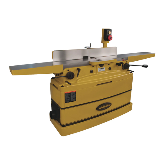
Description The PJ-882 Jointers are built upon a parallelogram design. This design allows independent adjustment of sections of the infeed and outfeed tables to ensure the tables remain parallel with the cutterhead and with each other. The fence has a tilting capacity of 45 degrees forward and backward, with positive stops. -
Page 8: Unpacking
Report any damage immediately to Push blocks your distributor and shipping agent. Do not discard any shipping material until the Jointer is 8mm/10mm Open-end wrench (PJ-882 only) assembled and running properly. 3mm Hex wrench (PJ-882 only) Compare the contents of your container with the... -
Page 9: Installation And Assembly
Installation and Assembly Tools required for assembly Forklift or hoist with straps/slings 14mm (or 9/16”) wrench or socket Cross-point (Phillips) screwdriver 3mm and 5mm hex wrenches (provided) 1. Remove any boards or straps that secure the Jointer to the pallet, and remove protective wrapping. -
Page 10: Installing Switch Arm
Installing Switch Arm 1. The switch arm was shipped in horizontal position. Loosen and remove the four socket head cap screws and flat washers on the bracket of the switch arm (Figure 3) with a 5mm hex wrench. Hold on to the switch arm while doing this, to prevent the arm from falling. -
Page 11: Dust Collection
cutterhead guard should have sufficient spring tension. Test it by swinging the guard away from the fence and then releasing it. The guard must always have enough spring tension to cover the unused part of the cutterhead during the cutting operation, and to swing back to contact the fence when the workpiece has cleared the area. -
Page 12: Extension Cords
*based on limiting the line voltage drop to 5V at 150% of the As received from the factory, the single-phase rated amperes. model of the PJ-882 Jointer is designed to run NR: Not Recommended. on 230 volt power only. Figure 8 The jointer has a grounding plug that looks like the plug illustrated in Figure 9;... -
Page 13: Adjustments
Three-Phase Test Run On the three-phase unit, after wiring has been completed, you should check that the wires have been connected properly: 1. Connect machine to power source and press the start button, shown in Figure 10. (See “Operating Controls” on page 25 for further information on the control switch.) 2. -
Page 14: Fence Movement
3. On the motor base plate, loosen the top hex nut (A, Figure 13), and lift up on the motor to create slack in the drive belt. Remove the drive belt from both pulleys. 4. Install the new drive belt around top and bottom pulleys, and tension it appropriately (see “Drive Belt Tension”). -
Page 15: Fence Stops
3. Rotate handwheel (C, Figure 16) until the desired angle is indicated on the scale (D, Figure 16). Or you can place your beveled workpiece on the table and against the fence, and rotate the handwheel (C, Figure 16) until the angle of the fence matches the bevel of your workpiece. -
Page 16: Fence Removal
Setting the 45° Backward Stop 1. The 45° backward stop is controlled by the screw (G, Figure 18), which will contact the back of the fence when the fence is tilted backward. 2. Flip the stop block (E, Figure 18) out of the way. -
Page 17: Setting Tables Coplanar
Setting Tables Coplanar For optimum performance of the jointer, the infeed and outfeed tables must be coplanar; that is, parallel front-to-back and side-to-side. If they are not parallel in both planes, the finished workpiece may have a slight taper across its width or length. -
Page 18: Setting Knives At Correct Height And Parallel To Outfeed Table
NOTE: On the front of the Jointer, the two outside cams are concealed by the hubs. You must remove the hub to expose the cam adjustment device. Remove the socket head cap screw and flat washer at the center with a 6mm hex wrench, and loosen the two setscrews in the hub (Figure 21 shows one of the two set screw holes). - Page 19 When you receive the jointer, the knives have been pre-set at the factory. However, the height and parallelism of the knives with the outfeed table should be checked, and any needed adjustments made, before operating the jointer. Height setting of knives is not applicable to the helical head models, in which the knife inserts are immediately at the proper height after installing.
- Page 20 Figure 27 illustrates the correct setting of outfeed table level with the knives. The workpiece will rest firmly on both tables with no open space under the finished cut. The outfeed table has now been locked at a standard height, level with the arc of the knives. NOTE: After the outfeed table has been set at the correct height, it should not be changed except for special operations or after replacing...
- Page 21 14. Slightly loosen the five gib screws (see Figure 31) with an 8mm wrench. (NOTE: The springs below the knife will cause the knife to rise.) 15. Turn the jack screw(s) with a hex wrench; clockwise to lower the setting of the knife in the cutterhead, counterclockwise to raise the setting of the knife.
-
Page 22: Outfeed Table Stop Screws
Outfeed Table Stop Screws The stop screw (B, Figure 33) limits the amount of fall of the outfeed table. The stop screw has been pre-set at the factory, but if future adjustment is ever needed, simply loosen the hex nut (A, Figure 33) and turn the screw (B, Figure 33) as needed with a 14mm wrench. -
Page 23: Replacing Knives (Straight Cutterhead Only)
Replacing Knives (Straight Cutterhead Only) Jointer knives are extremely sharp. Use caution and proceed slowly when working with or around the cutterhead. 1. Disconnect jointer from power source. 2. Remove the belt guard so that you can rotate the cutterhead by turning the motor pulley or by moving the drive belt. -
Page 24: Replacing Or Rotating Knife Inserts (Helical Cutterhead Only)
Replacing or Rotating Knife Inserts (Helical Cutterhead Only) Knife inserts are sharp; use caution when working with or around them. The knife inserts on the model PJ-882HH are four-sided. When dull, simply remove eac h insert, rotate it 90° for a fresh edge, and re- install it. -
Page 25: Operating Controls
3. Tighten hex nut (B, Figure 38). 4. Repeat for the other set screws as needed. NOTE: The outfeed table is pre-set at the factory tighter than the infeed table. If you find the outfeed table difficult to move with the lifting handle, loosen the two set screws on the outfeed table, as just described. -
Page 26: Hand Placement
Hand Placement At the start of the cut, the left hand holds the workpiece firmly against the infeed table and fence while the right hand pushes the workpiece in a smooth, even motion toward the cutterhead. After the cut is under way, the new surface rests firmly on the outfeed table. -
Page 27: Jointing Short Or Thin Work
NOTE: The knives must be extended beyond the cutterhead by 1/32”. (see “Replacing Knives – Straight Cutterhead Only” on page 23 for this procedure). 4. Re-connect power. It is easier and safer to take a series of shallow cuts. Lower the infeed table 1/32”... -
Page 28: Maintenance
1. Release the fence locking handle (A, Figure 46) and remove the two hex nuts and washer (B, Figure 46) holding the fence to the slide bracket. Remove the fence assembly. 2. Remove the key (C, Figure 46) from the fence support. -
Page 29: Sharpening Standard Knives
Sharpening Standard Knives Knives should be kept sharp. This will contribute to better stock finish, longer machine life, and safer operation. A jointer knife hone provides a simple way to sharpen knives. Hones are available from many woodworking supply stores. Carefully read any instructions that accompany the hone. - Page 30 Troubleshooting – Operating Problems Trouble Probable Cause Remedy Finished stock is Knife or knife insert is higher than Raise outfeed table until it aligns with concave on back outfeed table. tip of knife/insert. See page 19. end. Finished stock is Outfeed table is higher than knife or Lower outfeed table until it aligns with concave on front end.
- Page 31 Troubleshooting – Mechanical and Electrical Problems Trouble Probable Cause Remedy Machine will not Verify unit is connected to power, on- start/restart or button is pushed in completely, and No incoming power. repeatedly trips stop-button is disengaged. See page circuit breaker or blows fuses.
-
Page 32: Optional Accessories
Optional Accessories 6296046...Knives (set of 3) – for model PJ-882 only 1791212...Knife Inserts (set of 10) – for model PJ-882HH only Replacement Parts Replacement parts are listed on the following pages. To order parts or reach our service department, call 1-800-274-6848, Monday through Friday (see our website for business hours, www.waltermeier.com). -
Page 33: Parts List: Stand Assembly
16 .... TS-081F032 ....Pan Head Screw..........1/4”-20x1/2”....4 17 .... TS-0680021 ....Flat Washer............1/4” ......4 18 .... 60B-425 ....Dust Chute ..................1 19 .... 3520B-140 ....Powermatic Nameplate ............... 1 20 .... 6296150 ....Warning Label ..................1 21 .... PJ882-521....Stand ...............1PH ......1 .... - Page 34 Index No. Part No. Description Size 43 .... PJ882-543....Electric Label............1Ph......1 ....PJ882-543A ....Electric Label............3Ph......1 45 .... 60B-447 ....Strain Relief .............1Ph......1 ....60B-447A ....Strain Relief .............3Ph......1 46 .... PJ882-546....Control Switch ..................1 47 .... PJ882-547....Switch Bracket..................1 48 ....
-
Page 35: Stand Assembly
Stand Assembly... -
Page 36: Parts List: Cutterhead Assembly (Model Pj-882 Only)
Parts List: Cutterhead Assembly (Model PJ-882 only) Index No. Part No. Description Size ....PJ882-CHA .....Cutterhead Assembly (Items 1 thru 5, and 10 thru 13) ......1 ....6296046 ....Knife ....................3 2 ....6296153 ....Knife Gib .................... 3 3 ....6296048 ....Key ..............5x5x25 mm ....1 4 .... -
Page 37: Parts List: Cutterhead Assembly (Model Pj-882Hh Only)
Parts List: Cutterhead Assembly (Model PJ-882HH only) Index No. Part No. Description Size ....PJ882HH-CA ...Cutterhead Assembly (Index # 1-10) ............ 1 1 ....TS-0267021 ....Socket Set Screw ..........1/4”-20x1/4”....2 2 ....PJ882-407....Cutterhead Pulley ................1 3 ....PJ882-405....Bearing Housing ................. 2 4 .... -
Page 38: Parts List: Fence Assembly
Parts List: Fence Assembly Index No. Part No. Description Size ....PJ882-FA ....Fence Assembly (Index #1 thru #49)............1 ....PJ882-101....Hand Wheel ..................1 2 ....TS-0267021 ....Socket Set Screw ..........1/4”-20x1/4”....3 3 ....TS-0207031 ....Socket Head Cap Screw ........1/4”-20x5/8”....4 4 .... -
Page 39: Fence Assembly
Fence Assembly... -
Page 40: Parts List: Outfeed Table And Base Assembly
Parts List: Outfeed Table and Base Assembly Index No. Part No. Description Size 1 ....PJ882-201....Rear (Outfeed) Table ................1 2 ....6285917 ....Push Block ..................2 3 ....PJ882-203....Shaft ....................2 4 ....PJ882-204....Shaft ....................1 5 ....PJ882-205....Key ..............5x5x22 mm ....1 6 .... -
Page 41: Outfeed Table And Base Assembly
Outfeed Table and Base Assembly... -
Page 42: Parts List: Infeed Table Assembly
Parts List: Infeed Table Assembly Index No. Part No. Description Size 1 ....PJ882-301....Front (Infeed) Table ................1 2 ....PJ882-302....Scale Label ..................1 3 ....PJ882-203....Shaft ....................2 4 ....PJ882-304....Shaft ....................1 5 ....PJ882-205....Key ..............5x5x22 mm ....1 6 .... - Page 43 Index No. Part No. Description Size 56 .... PJ882-246....Key ..............5x5x20 mm ....2 57 .... TS-0209031 ....Socket Head Cap Screw ........3/8”-16x3/4”....2 58 .... TS-0050031 ....Hex Cap Screw ..........1/4"-20x3/4”....2 59 .... PJ882-248....Table Raising Link ................1...
-
Page 44: Electrical Connections - 1 Phase, 230 Volt
Electrical Connections – 1 Phase, 230 Volt... -
Page 45: Electrical Connections - 3 Phase, 230 Volt
Electrical Connections – 3 Phase, 230 Volt... -
Page 46: Electrical Connections - 3 Phase, 460 Volt
Electrical Connections – 3 Phase, 460 Volt... - Page 48 WALTER MEIER (Manufacturing) Inc. 427 New Sanford Road LaVergne, Tennessee 37086 Phone: 800-274-6848 www.powermatic.com www.waltermeier.com...
Need help?
Do you have a question about the PJ-882 and is the answer not in the manual?
Questions and answers