Sign In
Upload
Download
Table of Contents
Contents
Add to my manuals
Delete from my manuals
Share
URL of this page:
HTML Link:
Bookmark this page
Add
Manual will be automatically added to "My Manuals"
Print this page
×
Bookmark added
×
Added to my manuals
Manuals
Brands
Powermatic Manuals
Power Tool
PJ882T
Operating instructions and parts manual
Powermatic PJ882T Operating Instructions And Parts Manual
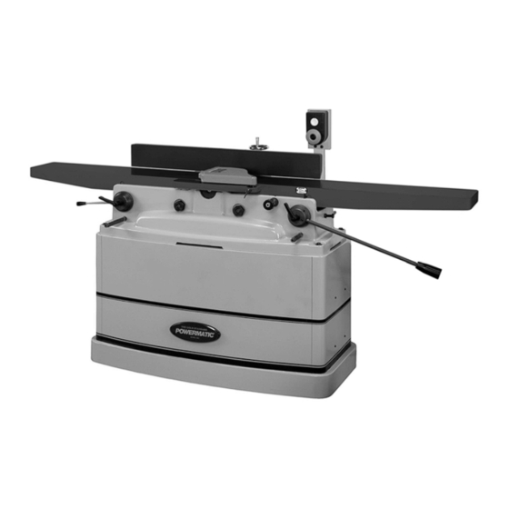
8-inch parallelogram jointer
Hide thumbs
1
2
Table Of Contents
3
4
5
6
7
8
9
10
11
12
13
14
15
16
17
18
19
20
21
22
23
24
25
26
27
28
29
30
31
32
33
34
35
36
37
38
39
40
41
42
43
44
page
of
44
Go
/
44
Contents
Table of Contents
Bookmarks
Table of Contents
Warranty and Service
Table of Contents
Warning
Introduction
Description
Specifications
Unpacking
Contents of the Shipping Container
Installation and Assembly
Installing Switch Arm
Installing Cutterhead Guard
Dust Collection
Grounding Instructions
Extension Cords
230 Volt, Single Phase Operation
Adjustments
Drive Belt Tension
Drive Belt Replacement
Fence Movement
Fence Stops
Fence Removal
Locking Handles
Setting Tables Coplanar
Setting Knives at Correct Height and Parallel to Outfeed Table
Outfeed Table Stop Screws
Setting Infeed Table (Depth of Cut)
Infeed Table Depth Stop
Infeed Table Stop Screws
Replacing Knives (Straight Cutterhead Only)
Replacing or Rotating Knife Inserts (Helical Cutterhead Only)
Eliminating "Play" in Tables
Operating Controls
Start/Stop
Safety Key
Operation
Hand Placement
Surfacing
Edge Jointing
Rabbeting
Jointing Short or Thin Work
Jointing Warped Surfaces
Beveling
Direction of Grain
Skewing (Shear Cutting)
Maintenance
Sharpening Standard Knives
Cutterhead Repairs
Optional Accessories
Replacement Parts
Parts List: Stand Assembly
Stand Assembly
Parts List: Cutterhead Assembly (Model PJ-882 & PJ882T Only)
Parts List: Cutterhead Assembly (Model PJ-882HH & PJ-882HHT Only)
Parts List: Fence Assembly
Fence Assembly
Parts List: Outfeed Table and Base Assembly
Outfeed Table and Base Assembly
Parts List: Infeed Table Assembly
Electrical Connections - 1 Phase, 230 Volt
Advertisement
Quick Links
Download this manual
Operating Instructions and Parts Manual
8-inch Parallelogram Jointer
Model PJ-882, PJ882T, PJ-882HH and PJ-882HHT
Powermatic
427 New Sanford Road
LaVergne, TN 37086
Part No. M-1610079
Ph.: 800-274-6848
Edition 12 04/2023
www.powermatic.com
Copyright © 2022 Powermatic
Table of
Contents
Previous
Page
Next
Page
1
2
3
4
5
Advertisement
Table of Contents
Need help?
Do you have a question about the PJ882T and is the answer not in the manual?
Ask a question
Questions and answers
Related Manuals for Powermatic PJ882T
Power Tool Powermatic PJ-882 Operating Instructions And Parts Manual
8-inch parallelogram jointer (96 pages)
Power Tool Powermatic PJ882 Operating Instructions And Parts Manual
8-inch parallelogram jointer (48 pages)
Power Tool Powermatic PJ-882 Operating Instructions And Parts Manual
8-inch parallelogram jointer (48 pages)
Power Tool Powermatic PJ-882HH Specification Sheet
8" parallelogram jointer (5 pages)
Power Tool Powermatic PJ1696 Operating Instructions And Parts Manual
16-inch jointer (40 pages)
Power Tool Powermatic PJ1696 Operating Instructions And Parts Manual
16-inch (36 pages)
Power Tool Powermatic PJ1696T Operating Instructions And Parts Manual
16-inch jointer (36 pages)
Power Tool Powermatic PJ1696 Specifications
16" jointer (4 pages)
Power Tool Powermatic 3-Roll Powered Stock Feeder PF3-JR Operating Instructions Manual
3-roll powered stock feeder (28 pages)
Power Tool Powermatic PF3-JR Operating Instructions And Parts Manual
3-roll powered stock feeder (28 pages)
Power Tool Powermatic PM2800 Brochure
18” variable speed drill press (4 pages)
Power Tool Powermatic PM2800B Operating Instructions And Parts Manual
18-inch variable speed drill press (24 pages)
Power Tool Powermatic PM2820EVS Operating Instructions And Parts Manual
20-inch variable speed drill press (36 pages)
Power Tool Powermatic PM2500 Series Operating Instructions And Parts Manual
(48 pages)
Power Tool Powermatic PJ-882HHT Operating Instructions And Parts Manual
8-inch parallelogram jointer (44 pages)
Power Tool Powermatic PM2815FS Operating Instructions And Parts Manual
15-inch variable speed drill press (32 pages)
This manual is also suitable for:
Pj-882
Pj-882hh
Pj-882hht
Table of Contents
Print
Rename the bookmark
Delete bookmark?
Delete from my manuals?
Login
Sign In
OR
Sign in with Facebook
Sign in with Google
Upload manual
Upload from disk
Upload from URL


Need help?
Do you have a question about the PJ882T and is the answer not in the manual?
Questions and answers