Powermatic PJ1696 Operating Instructions And Parts Manual
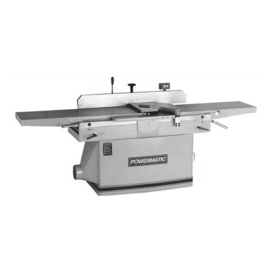
16-inch jointer
Hide thumbs
Also See for PJ1696:
- Specifications (4 pages) ,
- Operating instructions and parts manual (36 pages) ,
- Operating instructions and parts manual (36 pages)
Table of Contents
Advertisement
Quick Links
Advertisement
Table of Contents

Related Manuals for Powermatic PJ1696


Summary of Contents for Powermatic PJ1696
- Page 1 This Manual is Bookmarked Operating Instructions and Parts Manual 16-inch Jointer Model PJ1696 WMH TOOL GROUP 2420 Vantage Drive Elgin, Illinois 60124 Part No. M-0460269 Ph.: 800-274-6848 Revision B1 6/06 www.wmhtoolgroup.com Copyright © WMH Tool Group...
-
Page 2: Warranty And Service
This warranty covers only the initial purchaser of the product. WHAT IS THE PERIOD OF COVERAGE? The general POWERMATIC warranty lasts for the time period specified in the product literature of each product. WHAT IS NOT COVERED? The Five Year Warranty does not cover products used for commercial, industrial or educational purposes. Products with a Five Year Warranty that are used for commercial, industrial or education purposes revert to a One Year Warranty. -
Page 3: Table Of Contents
WMH Tool Group sells through distributors only. The specifications in WMH catalogs are given as general information and are not binding. Members of WMH Tool Group reserve the right to effect at any time, without prior notice, those alterations to parts, fittings, and accessory equipment which they may deem necessary for any reason whatsoever. -
Page 4: Safety Rules
Read the manual. Read, understand, and follow the safety instructions found in this manual. Know the limitations and hazards in using the model PJ1696 Jointer. Decals are placed on each machine as reminders of good safety practice. - Page 5 7-1/2 Horsepower at 5,200 R.P.M. Use of a larger horsepower motor or higher cutterhead speed voids the warranty and Powermatic holds itself harmless for any injury which may result. If you are not thoroughly familiar with the operation of jointers, obtain advice from your supervisor, instructor or other qualified person.
- Page 6 Familiarize yourself with the following safety notices used in this manual: CAUTION: (This means that if precautions are not heeded, it may result in minor or moderate injury, and/or possible machine damage) WARNING: (This means that if precautions are not heeded, it could result in serious injury or possibly even death).
-
Page 7: Features
FEATURES: PJ1696 Jointer FIGURE 4 Outfeed table 14. Guard Bracket Block Fence 15. Pushbutton Switch Fence Handle 16. Cabinet Lock Lever 17. Table Lock Cast Housing 18. Door Latch Control Handle - Forward/Backward 19. Cabinet Door Rack Column 20. Table Raising/Lowering Handle Cutterhead Guard Plate 21. -
Page 8: Specifications
Gross weight ........................1400 lbs. (636 kgs.) NOTE: The above specifications were current at the time this manual was published, but because of our policy of continuous improvement, Powermatic reserves the right to change specifications without notice and without incurring obligations. -
Page 9: Receiving The Jointer
RECEIVING THE JOINTER Carefully unpack the jointer and all loose items from the wood crate and inspect for damage. Any damage should be reported to your distributor and shipping agent immediately. Before proceeding further, read your manual thoroughly to familiarize yourself with proper assembly, set-up, maintenance, safety and operating procedures. -
Page 10: Fence Installation
Remove the bolts holding the jointer to the skid, and lift the machine from the skid using a hoist. The strap should be suitable to lift 1320 pounds of weight, and should be placed under the base casting as shown in Figure 6. DO NOT place strap under the tables. -
Page 11: Start/Stop Switch
START / STOP SWITCH The arm (E-Fig. 9) on which the pushbutton switch is located is shipped in the down position. The screws (F-Fig. 9) should be loosened with a 10mm hex wrench and the arm pivoted to upright position. Re-tighten screws. -
Page 12: Replacing Knife Inserts
See Figure 12. REPLACING KNIFE INSERTS The cutterhead on the PJ1696 is a solid steel helical insert design with 56 two-sided standard knives, and two rabbet knives on the outboard end of the cutterhead. Replacing... - Page 13 Lower the outfeed table until the straight edge contacts a knife. Rock the cutterhead slightly to make sure the apex of the knife is contacting the straight edge. Lock the outfeed table at that setting. After the outfeed table has been set at the correct height, it should not be changed except for special operations or after replacing knives.
-
Page 14: Table Raising Limit Blocks
TABLE RAISING LIMIT BLOCKS A limit block, shown in Figure 17, is mounted to the rear of each table. It sets the maximum height the tables can be raised, and is pre-set at the factory. If adjustment is ever needed, loosen the hex nut (E-Fig. 17) and turn the screw (F-Fig. -
Page 15: Hand Placement
HAND PLACEMENT At the start of the cut, the left hand holds the work firmly against the infeed table and fence while the right hand pushes the work toward the knives. After the cut is under way, the new surface rests firmly on the outfeed table. The left hand should press down on this part, at the same time maintaining flat contact with the fence. -
Page 16: Jointing Warped Surfaces
Use push blocks to rabbet cut whenever possible. The rabbeting capacity is 3/4”. 1. Disconnect machine from power source. 2. Set fence for desired width of rabbet. 3. Check width of the rabbet by measuring the distance from end of knife in the cutterhead to the fence. -
Page 17: Taper Cuts
TAPER CUTS One of the most useful jointer operations is cutting an edge to a taper. The method can be used on a wide variety of work. Tapered legs of furniture are a common example. Instead of laying the piece on the infeed table, lower the forward end of the work onto the outfeed table. -
Page 18: Cutterhead Repairs
(E- Fig. 26). IMPORTANT: If the bearings (G-Fig. 26) need replacement, Powermatic strongly recommends this be done by qualified service personnel. The bearings are press fitted and must be removed with an arbor press. -
Page 19: Blade Inserts
An advantage of the helical style cutterhead is that inserts. if knife inserts develop nicks, these inserts can be individually flipped or replaced without the need to disturb the other inserts. TROUBLE-SHOOTING (PJ1696 Jointer) PROBLEM POSSIBLE CAUSE SOLUTION [with page #] Finished stock is concave Knife tip is higher than outfeed table. -
Page 20: Cutterhead Assembly
Description Size Qty.... PJ1696-001 ....Cutterhead Assembly (Items 2 thru 12 & 17 thru 21) ......1 1 ..PJ1696-014 ....Cutterhead................... 1 2 ..PJ1696-002 ....Left Bearing Housing ................1 3 ..BB-6204ZZ ....Ball Bearing ..................2 4 .. -
Page 21: Cutterhead Assembly
Cutterhead Assembly (PJ1696 Jointer) - Page 22 35 ..PJ1696-120 ....Handle Rod..................1 36 ..PJ1696-121 ....Handle....................1 37 ..PJ1696-122 ....Stop Plate, -90 Degree ................ 1 38 ..PJ1696-123 ....Collar....................1 39 ..TS-2361081....Lock Washer ..........M8........1 40 ..
-
Page 23: Fence Assembly
Fence Assembly (PJ1696 Jointer) - Page 24 13 ..TS-1533032....Pan Head Machine Screw......M5 x 10 ......2 14 ..PJ1696-208 ....Terminal Strip..........30A ........1 15 ..PJ1696-209 ....Pan Head Machine Screw......M5 x 25 ......2 16 ..PJ1696-210 ....Switch Arm ..................1 17 ..
-
Page 25: Stand Assembly
Stand Assembly (PJ1696 Jointer) -
Page 26: Bed Assembly
12 ..PJ1696-305 ....Pivot Shaft................... 2 13 ..PJ1696-319 ....Cap Nut ............. 1/2-13........ 2 14 ..PJ1696-306 ....Hex Cap Screw.......... 1/2-13 x 2 3/4 ....2 15 ..TS-0680061....Flat Washer..........1/2........2 16 ..PJ1696-307 ....Lock Handle..................2 17 .. -
Page 27: Bed Assembly
Bed Assembly (PJ1696 Jointer) - Page 28 6 ..TS-1523051....Socket Set Screw ........M6 x 16 ......2 7 ..TS-1523031....Socket Set Screw ........M6 x 10 ......1 8 ..PJ1696-408 ....Special Washer ................... 1 9 ..PJ1696-409 ....Flat Head Machine Screw......M8 x 16 ......1...
-
Page 29: Cutterhead Guard Assembly
Cutterhead Guard Assembly (PJ1696 Jointer) -
Page 30: Infeed Table Assembly
12 ..PJ1696-508 ....Adjustment Shaft ................. 2 13 ..TS-1525031....Socket Set Screw ........M10 x 16 ......8 14 ..PJ1696-509 ....Special Bolt, for Spring ......1/4-20 x 3 ......2 15 ..TS-0570011....Hex Nut ............. 1/4-20........ 4... -
Page 31: Infeed Table Assembly
Infeed Table Assembly (PJ1696 Jointer) -
Page 32: Outfeed Table Assembly
Description Size Qty. 1 ..PJ1696-601 ....Outfeed Table Lip ................1 2 ..PJ1696-602 ....Outfeed Table..................1 3 ..TS-1505061....Socket Head Cap Screw ......M10 x 40 ......4 4 ..PJ1696-603 ....Table Lifting Support Base..............1 5 .. -
Page 33: Outfeed Table Assembly
Outfeed Table Assembly (PJ1696 Jointer) -
Page 34: Motor Assembly
Description Size Qty. 1 ..PJ1696-701 ....Motor........7-1/2HP, 3Ph 230/460V, 60Hz ....1 2 ..PJ1696-702 ....Motor Sheave ..................1 3 ..TS-1525011....Socket Set Screw ........M10 x 10 ......2 4 ..PJ1696-703 ....Motor Bracket ..................1 5 .. -
Page 35: Motor Assembly
Motor Assembly (PJ1696 Jointer) -
Page 36: Electrical Schematic
ELECTRICAL SCHEMATIC (PJ1696 Jointer) -
Page 37: Preventive Maintenance
Preventive Maintenance Checklist for Model PJ1696 Jointer Monthly: ] Inspect entire machine for loose bolts, nuts, screws. Tighten and replace as necessary. ] Clean table and cutterhead area, removing sawdust and chips with a soft bristle brush. Remove gum and pitch with oven cleaner. -
Page 38: Replacement Parts
Replacement Parts To order parts or reach our service department, call 1-800-274-6848 between 7:30 a.m. and 6:00 p.m. (CST), Monday through Friday. Having the Model Number and Serial Number of your machine available when you call will allow us to serve you quickly and accurately. - Page 40 WMH Tool Group 2420 Vantage Drive Elgin, Illinois 60124 Phone: 800-274-6848 www.wmhtoolgroup.com...
Need help?
Do you have a question about the PJ1696 and is the answer not in the manual?
Questions and answers