Table of Contents
Advertisement
Quick Links
Advertisement
Table of Contents

Related Manuals for Powermatic PM2815FS


Summary of Contents for Powermatic PM2815FS
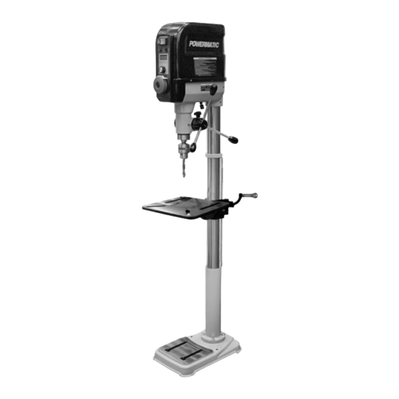
- Page 1 Operating Instructions and Parts Manual 15-inch Variable Speed Drill Press Model PM2815FS Powermatic 427 New Sanford Road LaVergne, Tennessee 37086 Part No. M-PM1-33 Ph.: 800-274-6848 Edition 1 08/2023 www.powermatic.com Copyright © 2023 Powermatic...
-
Page 2: Important Safety Instructions
If used for other purposes, “horseplay” are careless acts that can result in Powermatic disclaims any real or implied serious injury. warranty and holds itself harmless from any 21. Always maintain a balanced stance so that you injury that may result from that use. - Page 3 SAVE THESE INSTRUCTIONS Familiarize yourself with the following safety notices used in this manual: This means that if precautions are not heeded, it may result in minor injury and/or possible machine damage. This means that if precautions are not heeded, it may result in serious injury or possibly even death.
-
Page 4: About This Manual
If there are questions or comments, please contact your local supplier or Powermatic. Powermatic can also be reached at our web site: www.powermatic.com. -
Page 5: Table Of Contents
13.3.1 PM2815FS Control Panel – Exploded View ..................24 13.3.2 PM2815FS Control Panel – Parts List ....................24 13.4.1 PM2815FS Top Cover & PCB Assembly – Exploded View ..............25 13.4.2 PM2815FS Top Cover & PCB Assembly – Parts List ................25 13.5.1 PM2815FS Work Table Assembly –... -
Page 6: Specifications
L = length, W = width, H = height The specifications in this manual were current at time of publication, but because of our policy of continuous improvement, Powermatic reserves the right to change specifications at any time and without prior notice, without incurring obligations. -
Page 7: Base Hole Centers
4.1 Base Hole Centers Figure 4-1: Hole Centers... -
Page 8: Unpacking
If any parts are missing, contact your distributor or Powermatic. (Check machine first to see if any parts were pre-assembled.) Do not discard carton or packing material until drill press is assembled and running satisfactorily. -
Page 9: Assembly
6.0 Assembly vibration, sliding or moving of drill press during operation. Do not use a mobile base with this machine. The drill press should be placed in a dry area, with a level floor and good lighting. Provide enough 4. Insert shaft of worm drive (R, Figure 6-2) space around machine to allow for operations and through table bracket hole, while meshing worm any adjustments or servicing. - Page 10 block, and through-holes near each end to accept eye bolts with fasteners, as shown. 2. Place this block onto main spindle, run straps through the eyebolts, and another strap toward the rear of head as shown in Figure 6-9. 3. Carefully lift head and place on column. Figure 6-4 8.
- Page 11 Figure 6-10 2. Cut the corners of the shipping box and fold down the cardboard sides to better expose the drill head (Figure 6-11). Trim away excess to prevent a potential tripping hazard. Figure 6-12 2. Install three turret handles into hub on the side of drill head (Figure 6-12).
-
Page 12: Electrical Connections
The PM2815FS drill press is rated and prewired for 120V power. The drill press comes with a plug designed for use on a circuit with a grounded outlet that looks like the one pictured in A, Figure 7-1. -
Page 13: Chuck And Arbor Removal
8.2 Chuck and Arbor Removal column rack. Re-tighten locking handle (A) before attempting to drill. Refer to Figure 8-3 1. Disconnect machine from power source. 2. Lower quill assembly with turret handles to expose slot. Rotate chuck to align slots. 3. -
Page 14: Quill Retraction Lock
2. Rotate turret handles (G) to lower spindle to the point at which it is to be locked, and hold turret handles stationary in this position. 3. Rotate scale ring (H) clockwise all the way until it stops. You should be able to feel and hear when lock ring reaches the end of its rotation. -
Page 15: Led Light
Do not assume that no light means there is no power to the machine. If the bulb is bad, there will be no indication. Always check before use. Spindle rotation ON – (D) Spindle rotation OFF – (E). Spindle coasting will stop within 10 seconds from maximum RPM. -
Page 16: General Inspection
10.3 General Inspection Clean sawdust from the table with a brush (do not use bare hands). Before each operation of your PM2815FS drill Periodically: press, make a habit of checking that all locking handles, set screws, bolts, etc., are tight on the table Apply a light film of oil to the quill and column. -
Page 17: Troubleshooting The Pm2815Fs Drill Press
12.0 Troubleshooting the PM2815FS Drill Press 12.1 Mechanical and Electrical * WARNING: Some corrections may require a qualified electrician. Symptom Possible Cause Correction * Not connected to power. Check all plug connections. Drill press will not start Fuse blown, or circuit breaker tripped on Replace fuse or reset circuit breaker. -
Page 18: Error Codes On Digital Readout
12.2 Error Codes on Digital Readout Error Correction Error source Description code Press off button to clear error If load exceeds 15A for over 5 seconds, ERR-1 Overload protector code, then press on to restart PCB shuts off motor. machine. Motor revolution Motor won’t start within 25 seconds of Replace motor. -
Page 19: Replacement Parts
Non-proprietary parts, such as fasteners, can be found at local hardware stores, or may be ordered from Powermatic. Some parts are shown for reference only and may not be available individually. -
Page 20: Pm2815Fs Gear Box Assembly - Exploded View
13.1.1 PM2815FS Gear Box Assembly – Exploded View... -
Page 21: Pm2815Fs Gear Box Assembly - Parts List
13.1.2 PM2815FS Gear Box Assembly – Parts List Index No. Part No. Description Size Qty. 1 ....PM2815BT-101 .... Headstock ......................1 2 ....PM2815BT-102 .... Gear Box Cover ....................1 3 ....PM2815BT-103 .... Gasket ........................1 4 .... -
Page 22: Pm2815Fs Quill And Laser Assembly - Exploded View
13.2.1 PM2815FS Quill and Laser Assembly – Exploded View... -
Page 23: Pm2815Fs Quill And Laser Assembly - Parts List
13.2.2 PM2815FS Quill and Laser Assembly – Parts List Index No. Part No. Description Size Qty....PM2815BT-SA ..... Spindle Assembly (Item #1-#7) ................1 ....PM2815BT-201 .... Quill ........................1 2 ....PM2815BT-202 .... Spindle ......................... 1 3 .... -
Page 24: Pm2815Fs Control Panel - Exploded View
13.3.1 PM2815FS Control Panel – Exploded View 13.3.2 PM2815FS Control Panel – Parts List Index No. Part No. Description Size Qty....PM2815BT-CPA ... Control Panel Assembly (item #3 - #16) ............... 1 1 ....TS-1503051 ....Socket Head Cap Screw ..........6-1.0 x 20 ......4 2 .... -
Page 25: Pm2815Fs Top Cover & Pcb Assembly - Exploded View
13.4.1 PM2815FS Top Cover & PCB Assembly – Exploded View 13.4.2 PM2815FS Top Cover & PCB Assembly – Parts List Index No. Part No. Description Size Qty. 1 ....TS-2361061 ....Lock Washer ..............M6 ........2 2 ....TS-1503051 ....Socket Head Cap Screw ..........6x20 ........ 2 3 .... -
Page 26: Pm2815Fs Work Table Assembly - Exploded View
13.5.1 PM2815FS Work Table Assembly – Exploded View... -
Page 27: Pm2815Fs Work Table Assembly - Parts List
13.5.2 PM2815FS Work Table Assembly – Parts List Index No. Part No. Description Size Qty....PM2815BT-TA ..... Table Assembly (item #1 - #25) ................1 ....PM2815BT-501 .... Table Bracket ....................... 1 2 ....PM2820EVS-502 ..Gear ........................1 3 .... -
Page 28: Pm2815Fs Column Assembly - Exploded View
2 ....TS-1505051 ....Socket Head Cap Screw ..........M10x35 ......4 3 ....PM2815FS-703 .... Rack ................Floor Standing ....1 4 ....PM2815FS-704 .... Column Holder Kit (Item #4, #5 & #7) ......Floor Standing ....1 5 ............Column ................. Floor Standing ....1 6 .... -
Page 29: Optional Accessories
14.0 Optional accessories The following items will add functionality to your machine. See our website for more details, and to order accessories. 1792821 Storage Set 1792822 Tool Holder... -
Page 30: Electrical Connections For Pm2815Fs Drill Press
15.0 Electrical Connections for PM2815FS Drill Press... -
Page 31: Warranty And Service
16.0 Warranty and Service Powermatic warrants every product it sells against manufacturers’ defects. If one of our tools needs service or repair, please contact Technical Service by calling 1-800-274-6846, 8AM to 5PM CST, Monday through Friday. Warranty Period The general warranty lasts for the time period specified in the literature included with your product or on the official Powermatic branded website. - Page 32 427 New Sanford Road LaVergne, Tennessee 37086 Phone: 800-274-6848 www.powermatic.com...
Need help?
Do you have a question about the PM2815FS and is the answer not in the manual?
Questions and answers