Subscribe to Our Youtube Channel
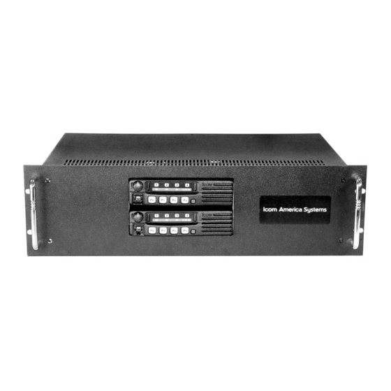
Summary of Contents for Icom CY-F121S
- Page 1 INSTRUCTION MANUAL VHF FM REPEATER UHF FM REPEATER American Communication Systems ™ Discover the Power of Communications http://www.ameradio.com TO ORDER – VISIT...
-
Page 2: Explicit Definitions
AVOID using or placing the repeater in areas The Icom America Systems logo is a trademark The Icom America Systems logo is a trademark with temperatures below –30°C (–22°F) or above of Icom, Inc. of Icom, Inc. -
Page 3: Supplied Accessories
FORWARD SUPPLIED ACCESSORIES Thank you for purchasing this Icom America The following accessories are supplied with CY-F121S/221S series Systems CY-F121S/221S UHF FM REPEATER With proper care, this product should provide [AC120V version] you years of trouble-free operation. ➀ AC power cable (OPC-510) ….....……… 1 ... -
Page 4: Panel Description
PANEL DESCRIPTION ■ Front Panel ➏ ➏ ➎ ➎ ➊ ➋ ➌ ➍ ➐ MICROPHONE/SPEAKER CONNECTOR ➊ VOLUME CONTROL [VOLUME] ➋ [MIC/SP] Adjusts the audio output level. This 8-pin modular jack accepts the optional microphone. DEALER PROGRAMMABLE KEYS ➌ P0, P1, P2, P3 ➀ +8 V DC output (Max. -
Page 5: Front Panel
PANEL DESCRIPTION ■ Front Panel ➊ ➊ ➋ ➋ ➍ ➍ ➌ ➌ ➎ ➎ AF VOLUME CONTROL KNOB DEALER-PROGRAMMABLE KEYS ➊ ➍ Rotate the knob to adjust the audio output [P0] to [P3] level. Desired functions can be programmed independently by your dealer. •... -
Page 6: Rear Panel
PANEL DESCRIPTION ■ Rear Panel ➌ ➊ ➐ ➏ ➋ ➍ ➎ POWER SWITCH [POWER] AC POWER SOCKET [AC] ➊ ➎ Toggles to turn the repeater power ON or Connects the supplied AC power cable to a OFF. Located on the back panel of the domestic AC outlet. - Page 7 PANEL DESCRIPTION ■ Repeater Controller Programming Mobile Radios HANG ON TIME CONFIGURATION JP4 T sec. ➀ Transmitter: • Go to LMR>Memory CH>Free, Program the TX and RX to the transmit frequency • Set the CTCSS/CDCSS Tone • Set RF Power to High •...
- Page 10 PANEL DESCRIPTION ■ Accessory connector DB25 Pin Outs Confi guration Pin Name Description Specifi cation Vcc TX +15V DC Supply for External Controller, TX Maximum 1 A Unit GND TX DC Ground, TX Unit Busy TX Output Terminal for Busy Signal, TX Unit Open Open Collector+OFF, 0V=ON...
-
Page 11: Installation And Connections
Select a duplexer according to the transmitting and receiving frequencies. Ask your For a description and a diagram of accessory Dealer for details. equipment included with the CY-F121S/221S series, see ʻSupplied accessoriesʼ of this ■ Grounding manual. To prevent electrical shock, television interference ■ Selecting a location... - Page 12 INSTALLATION AND CONNECTIONS Required Connections ■ [DC POWER INPUT TERMINAL] Make sure the back up battery is correctly connected. Use a cable with following current capacity. Solder or clamp the cable plug when connecting the power cable to the backup battery to prevent voltage drops. Power cable current capacity: 25 A or more [TX(TX•RX) ANT] [TX(TX•RX) ANT]...
- Page 13 Check the source voltage before connecting the power cable. The CY-F121S/221S series can operate with an AC or DC power supply. If AC power is interrupted • DO NOT place the backup battery on or near when operating the repeater with an AC power the repeater.
-
Page 14: Optional Unit Installation
OPTIONAL UNIT INSTALLATION ■ Opening the repeaterʼs case Follow the case and cover opening procedures shown here when an optional unit is installed or adjust the internal units, etc. CAUTION: Disconnect the AC power cable and/or DC power cable from the repeater. Otherwise, there is danger of electric shock and/or equipment damage. -
Page 15: Operation
OPERATION ■ Turning power ON ➀ On rear panel, push [POWER] to turn power ■ Receiving and transmitting Receiving ➀ Push [POWER] to turn power ON. ➁ Rotate [VOLUME] to adjust the audio output level. ➂ Push [1; 2; 3; 4] to select the desired channel. -
Page 16: Maintenance
MAINTENANCE ■ Fuse replacement If a fuse blows or the repeater stops functioning, try to fi nd the source of the problem, and replace the damaged fuse with a new, rated fuse. Replace the circuitry fuse as shown below. “There are two fuses: The left fuse, as pictured, is for repeater TX The right fuse is for repeater RX”... -
Page 17: Specifications And Options
SPECIFICATIONS AND OPTIONS ■ Specifi cations ◆ CY-F121S Receiver General •Receive system: Double-conversion superheterodyne system •Frequency coverage : 136.000-174.000 MHz* •Intermediate frequency: : 46.35 MHz, 2 : 450 kHz •Channel spacing : 12.5/25 kHz (Narrow/Wide) •Sensitivity: 0.25 µV at 12 dB SINAD •Number of channels... - Page 18 ■ Options •Modulation system: Variable reactance freq. modulation •Max. frequency deviation: ±2.5 kHz [Narrow] •HM-100 HAND MICROPHONE ±5.0 kHz [Wide] •HM-100TN DTMF MICROPHONE •Frequency Error: ±2.5 ppm Hand microphone with a DTMF keypad •Spurious emission: 70 dB typical •SM-25 DESKTOP MICROPHONE •Adjacent channel power: 60 dB [Narrow]...
- Page 20 MEMO...
- Page 21 Count on us! 7008...


Need help?
Do you have a question about the CY-F121S and is the answer not in the manual?
Questions and answers