Table of Contents
Advertisement
Advertisement
Table of Contents

Subscribe to Our Youtube Channel
Summary of Contents for Icom CY 6000
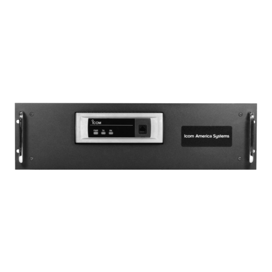
- Page 1 INSTRUCTION MANUAL VHF FM REPEATER CY 5000 UHF FM REPEATER CY 6000...
-
Page 2: Explicit Definitions
AVOID using or placing the repeater in areas The Icom America Systems logo is a trademark with temperatures below –30°C (–22°F) or above of Icom, Inc. +60°C (+140°F). Be aware that temperatures on a vehicle’s dashboard can exceed 80°C... -
Page 3: Supplied Accessories
FORWARD SUPPLIED ACCESSORIES Thank you for purchasing this Icom America The following accessory is supplied with VHF/UHF repeater. CY FR series Systems CY FR With proper care, this product should provide you [AC120V version] years of trouble-free operation. ➀ AC power cable (OPC-510) ….....……… 1 ... -
Page 4: Panel Description
PANEL DESCRIPTION ■ Front Panel ➊ MICROPHONE/SPEAKER CONNECTOR [MIC/SP] This 8-pin modular jack accepts the optional Field Service Aid. ➀ +8 V DC output (Max. 15 mA) ➁ Output port for PC programming ➂ AFO ➀ ➇ ➃ M PTT (Input port for TX control) ➄... - Page 5 PANEL DESCRIPTION ➒ ➌ ➑ ➊ ■ Rear Panel ➏ ➋ ➍ ➐ ➎ LIGHTED POWER SWITCH [POWER] GROUND TERMINAL [GND] ➊ ➏ Toggles to turn the repeater AC power ON Ground the repeater through this terminal or OFF. Located on the back panel of the to prevent electric shocks, TVI, BCI and other repeater.
-
Page 6: Specification
PANEL DESCRIPTION ■ Accessory connector DB25 Pin Outs Configuration Pin Name Description Specification Chassis fan sensor — Output terminal for serial communication data. — Input terminal for serial communication data. — Output terminal for request-to-send data. — Input terminal for clear-to-send data. —... -
Page 7: Installation And Connections
INSTALLATION AND CONNECTIONS ■ Unpacking ■ Duplexer After unpacking, immediately report any damage A duplexer is separately required when only to the delivering carrier or dealer. Keep the one antenna is used for both transmitting and shipping cartons. receiving. Select a duplexer according to the transmitting and receiving frequencies. - Page 8 INSTALLATION AND CONNECTIONS Required Connections ■ [DC POWER INPUT TERMINAL] Make sure the back up battery is correctly connected. Use a cable with following current capacity. Solder or clamp the cable plug when connecting the power cable to the backup battery to prevent voltage drops. Power cable current capacity: 25 A or more [TX(TX•RX) ANT] [RX ANT]...
- Page 9 INSTALLATION AND CONNECTIONS Power ■ In DC operation Make sure the AC [POWER] switch is turned OFF when connecting an AC power cable or a CAUTION: Voltages greater than 16 VDC backup battery (emergency power supply). will damage the repeater. Check the source voltage before connecting the power cable.
-
Page 10: Optional Unit Installation
OPTIONAL UNIT INSTALLATION ■ Opening the repeater’s case Follow the case and cover opening procedures shown here when an optional unit is installed or adjust the internal units, etc. CAUTION: Disconnect the AC power cable and/or DC power cable from the repeater. Otherwise, there is danger of electric shock and/or equipment damage. -
Page 11: Operation
OPERATION ■ Turning power ON ➀ On rear panel, toggle AC Power Switch up to turn AC power ON. ■ Receiving and transmitting Receiving ➀ Connect optional Field service Aid Microphone/Speaker. •When receiving a signal, RX indicator turns ON and audio is emitted from the speaker. -
Page 12: Maintenance
MAINTENANCE ■ Fuse replacement CAUTION If a fuse blows or the repeater stops functioning, DISCONNECT the DC power try to find the source of the problem, and replace cable from the repeater. Otherwise, there is the damaged fuse with a new, rated fuse. a danger of electric shock and/or equipment damage. -
Page 13: Specifications And Options
SPECIFICATIONS AND OPTIONS ■ Specifications (See UR Service Manual for module specifications) ◆ UR-FR5000 GENERAL Power supply 105-130 VAC 50/60 hz 5A Max requirement (nominal) 185-250 VAC 50/60 hz 13.6 VDC (nominal) 16.2 Amp Max Dimensions (Projections 480 (W) x 133 (H) x 364 (D) mm; not included) 18.90 (W) x 524 (H) x 14.33 (D) in. - Page 14 ■ Options • Field Service Aid MICROPHONE SPEAKER • HM-152 HAND MICROPHONE • HM-152T DTMF MICROPHONE Hand microphone with a DTMF keypad • SM-25 DESKTOP MICROPHONE • SP-22 SPEAKER • IAS VHF DUP KIT VHF duplexer kit with RF jumpers •...
- Page 15 MEMO...
- Page 16 Count on us! ©2009 Icom America Inc. The Icom logo is a registered trademark of Icom Inc. All specifications and information is subject to change without notice or obligation. All other trademarks remain the property of their respective owners. 10084...


Need help?
Do you have a question about the CY 6000 and is the answer not in the manual?
Questions and answers