Advertisement
Quick Links
Advertisement

Subscribe to Our Youtube Channel
Related Manuals for Body Solid G3S


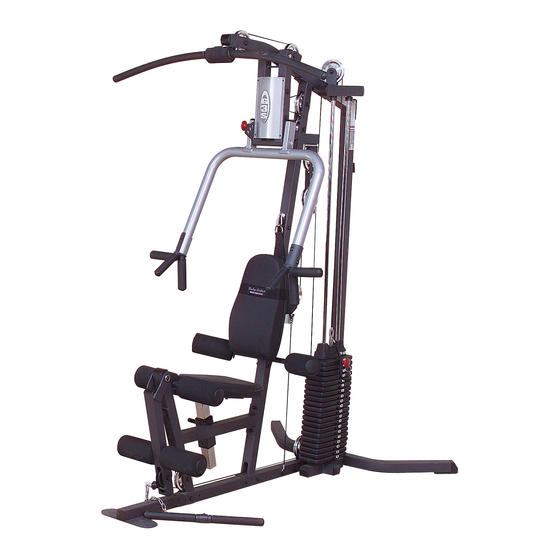
Summary of Contents for Body Solid G3S
- Page 1 Body-Solid ® A s s e m b l y I n s t r u c t i o n s...
- Page 2 S T E P Be careful to assemble all components in the sequence they are presented. NOTE: Finger tighten all hardware in this step. Do Not wrench tighten until end of step 4. Attach Frame Leveler (8) to Main Base Frame (A) as shown. Attach Main Base Frame (A) to Rear Base Frame (B) and Rear Vertical Frame (C) using: Two 43 (3/8”x 2 3/4”...
- Page 3 S T E P...
- Page 4 S T E P Be careful to assemble all components in the sequence they are presented. NOTE: Finger tighten all hardware in this step. Do Not wrench tighten until end of step 4. Attach one End Cap (4) to the front of Top Frame (E). Attach one End Cap (4) to the small horizontal arm sticking out of the Angled Vertical Frame (D) as shown.
- Page 5 S T E P...
- Page 6 S T E P Be careful to assemble all components in the sequence they are presented. NOTE: Finger tighten all hardware in this step. Do Not wrench tighten until end of step 4. Attach Seat Frame (H) and Flat Plate (70) to Angled Vertical Frame (D) using: Two 42 (3/8”...
- Page 7 S T E P...
- Page 8 S T E P Be careful to assemble all components in the sequence they are presented. Place two Weight Stack Risers (27) and two Rubber Donuts (11) onto Main Base Frame (A) over the two widest openings. Slide two Chrome Guide Rods (M) through the Rubber Donuts (11), two Weight Stack Risers (27), and into Main Base Frame (A).
- Page 9 S T E P...
- Page 10 S T E P Be careful to assemble all components in the sequence they are presented. NOTE: You will need to loosen two Allen Screws (76) inside Seated Press Arm Support (P) to remove Shaft (71) Attach Seated Press Arm Support (P) to Top Frame (E) with Shaft (71). TIghten Allen Screws (76) in Seated Press Arm Support (P).
- Page 11 S T E P...
- Page 12 S T E P Be careful to assemble all components in the sequence they are presented. Attach two End Caps (5) to the top and bottom of Back Pad Frame (S). Attach End Cap (4) to the end of Adjustable Back Pad Frame (T). Attach Back Pad (U) to Back Pad Frame (S) using: Two 45 (5/16”...
- Page 13 S T E P...
- Page 14 S T E P Be careful to assemble all components in the sequence they are presented. Attach Flat End Cap (2) to the bottom of the Adjustable Seat Pad Frame (V). Attach two End Caps (5) to the front and back of the Adjustable Seat Pad Frame (V). Attach Seat Pad (W) to the Adjustable Seat Pad Frame (V) using: Two 45 (5/16”...
- Page 15 S T E P...
- Page 16 S T E P Be careful to assemble all components in the sequence they are presented. NOTE: Leave all pulley bolts hand tight until step 13 Install Pulley (A3) into Seated Press Arm Support (P) as shown using: One 41 (3/8” x 7” hex head bolt) Two 57 (3/8”...
- Page 17 S T E P...
- Page 18 S T E P Be careful to assemble all components in the sequence they are presented. High Pulley Cable (66) Ball Stop End Metal Ball End 4270mm 14’ Note: All Pulleys in this step are 4 1/4” diameter, except where noted in step 8B. Leave all pulley bolts hand tight until step 13 is completed.
- Page 19 S T E P Diagram 1 Cable Installation 3 1/2” diameter pulley Start at high pulley station by inserting the Metal Ball End here. High Pulley Cable Diagram 2 Diagram 3 Pulley Installation Shroud Installation 3 1/2” diameter pulley...
- Page 20 S T E P Be careful to assemble all components in the sequence they are presented. High Pulley Cable (66) Ball Stop End Metal Ball End 4270mm 14” Note: All Pulleys in this step are 4 1/4” diameter. Leave all pulley bolts hand tight until step 13 is completed. See Diagram 2.
- Page 21 S T E P Diagram 1 Cable Installation WA R N I N G Selector Rod Top Bolt (22) must be threaded a minumum of 1/2” into the Selector Rod (21), and Jam Nut (25) tightened securely against spring lock washer (24) to ensure proper connection.
- Page 22 S T E P Be careful to assemble all components in the sequence they are presented. Low Pulley Cable (67) Ball Stop End Small Ball End 3730 mm 12’ 3” Note: All Pulleys in this step are 4 1/4” diameter, except where noted in step 10B. Leave all pulley bolts hand tight until step 13 is completed.
- Page 23 S T E P Diagram 1 Cable Installation Low Pulley Cable Start here at Leg Extension by inserting the Small Ball End here. Diagram 2 Pulley Installation 3 1/2” diameter pulley...
- Page 24 S T E P Be careful to assemble all components in the sequence they are presented. Low Pulley Cable (67) Ball Stop End Small Ball End 3730 mm 12’ 3” Short Cable (68) Stamped Eye End Stamped Eye End 2’ 6” 757 mm Note: All Pulleys in this step are 4 1/4”...
- Page 25 S T E P Diagram 1A Diagram 1 Cable Installation Start here by routing cable around Pulley (B4). Low Pulley Cable Diagram 2 Pulley Installation...
- Page 26 Cable(s) are sloppy and there is no resistance from the weight stack for the first few inches of the exercise. There are Five areas for cable adjustment on the G3S: A. Selector Rod Top Bolt (22) B. Two adjustments in Double Pulley Holder (X).
- Page 27 S T E P NOTE 1 Check Jam Nut (25) weekly to be sure it is tight and locked onto the Selector Rod (22). WA R N I N G Selector Rod Top Bolt (22) must be threaded a minumum of 1/2”...
- Page 28 G 3 S M a i n f r a m e P a r t s L i s t KEY# QTY PART# DESCRIPTION G3SMBF-A MAIN BASE FRAME G3SRBF-B REAR BASE FRAME G3SRVF-C REAR VERTICAL FRAME G3SAVF-D ANGLED VERTICAL FRAME G3STF-E TOP FRAME G3SFF-F...
- Page 29 G 3 S H a r d w a r e L i s t KEY# QTY PART# DESCRIPTION JACN.19 ACORN CAP NUT 3/16” ID -PREINSTALLED JFEC1.75 FLAT END CAP 1 3/4” x 1 3/4” JPW3 PLASTIC WASHER 3” JCEC1.8 2”...
- Page 30 G 3 S H a r d w a r e ( c o n t i n u e d ) KEY# QTY PART# DESCRIPTION JHEX.5X3PTB HEX HEAD BOLT 1/2” X 3” PARTIAL THREAD JHEX.37X7PTB HEX HEAD BOLT 3/8” X 7” PARTIAL THREAD JHEX.37X3PTB HEX HEAD BOLT 3/8”...
- Page 31 P a d s L i s t KEY# QTY PART# DESCRIPTION BACK PAD G3SBP-U G3SSP-W SEAT PAD C a b l e L i s t KEY# QTY PART# DESCRIPTION JHPC4155 HIGH PULLEY CABLE 4270 mm (14’) JLPC4030 LOW PULLEY CABLE 3730 mm (12’ 3”) JSC595 SHORT CABLE 757mm (2’...
- Page 32 G 3 S © Copyright 2003. Body-Solid. All rights reserved. Body-Solid reserves the right to change design and specifications when we feel it will improve the product. Body-Solid machines maintain several patented and patent pending features and designs. All rights reserved on all design patents and utility patents.
Need help?
Do you have a question about the G3S and is the answer not in the manual?
Questions and answers