
Related Manuals for Craftmade ProStar PS52


Summary of Contents for Craftmade ProStar PS52
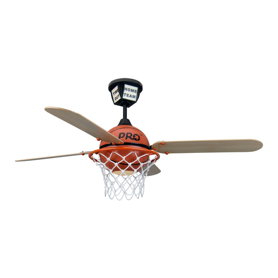
- Page 1 P r o S t a r C e i l i n g F a n Installation Instructions Instrucciones de instalación Instructions d’installation...
- Page 2 Read and Save These Safety Precautions 1. Turn off electricity at main switch before wiring or servicing fan in order to avoid possible electrical shock. 2. All wiring must be in accordance with the National Electric Code (ANSI/NFPA70-1999) and local electrical codes.
-
Page 3: Before Assembly
Before Assembly 1. Make sure that the fan voltage (120) is compatible with your own electrical system. 2. Check to make sure that your carton contains all the parts mentioned in the parts list. NOTE: The box can be used as a work space to prevent any damage on the ornamental surface. - Page 4 Turn off circuit breakers and wall switch to the fan supply line leads. Important: When using an existing outlet box, be sure the box is Preparation securely attached to the building structure and can support the full weight of the fan. Failure to do so can result in serious injury or death. b.) Angle Mount IMPORTANT: If using the angle mount method, check to make sure the ceiling angle is not steeper than 30 º...
-
Page 5: Outlet Box
Installing Mounting Bracket Support Beam “J” Hook (S8) Outlet Box (A) OUTLET BOX Ceiling Mounting Bracket (1) Bracket Screws & Washers (S3) Wood Screws (S1) Wood Screws (S1) NOTE: Do not mount directly to sheet rock or ceiling tile. Prior to securing mounting bracket, screw "J" hook (S7) into ceiling outlet box as a secondary support means. - Page 6 Downrod Assembly Locate downrod assembly (2). Loosen ball screw on black hanging ball to free lock pin. Black hanging ball will slide down. Remove ground screw and green ground wire. Remove hanging ball from downrod and save all parts. Insert fan wires through downrod.
- Page 7 Attaching Downrod to Motor Housing Thread the downrod onto the motor housing making sure the wires don’t get twisted. Insert safety bolt (S6) through flange & downrod and attach nut. Tighten firmly. Tighten set screw against downrod.
- Page 8 Place flange cover (4) over downrod assem- bly. Place canopy screw cover over down- rod. Place Canopy Night Light (3) over downrod (2). WARNING: Failure to completely tighten downrod as described in steps above could result in the fan loosening and possibly falling. Replace hanging ball, insert hanging pin through downrod and tighten ball screw through hanging ball into downrod.
- Page 9 Lift fan onto the mounting bracket (1). Turn housing until hanging ball seats itself into ball socket (listen for click). Connect Canopy Night Light (3) wiring harness (orange & white wires) together with “UP LIGHT” labeled wires from fan motor. (listen for click) For added security, attach safety cable from fan unit to "J"...
- Page 10 Ground 1. Connect fan wires to ceiling Wire White (Neutral) Connectors wires: white fan wire to white (S5) outlet wire, black to black and Black (Power) green to green. Wire connectors (S5) are provided for your conve- Ground White (Green) nience.
- Page 11 Attach Canopy Night Light (3) to the mounting bracket by placing canopy screws into keyed hole slots. Twist clockwise to lock into place. Tighten screws firmly. Seat the canopy screw cover into slots and twist to lock.
- Page 12 Assemble Blade (11) to Blade Arms (8) by inserting screw (S4) and securing with Blade Medallion (10). Support and attach Blade Assembly to Motor with Motor Screws (S2)
- Page 13 Seat Light Kit (5) into position and lock into place by twisting 1/4 turn. From light kit hole screw set screw into place firmly. Screw in Compact Florescent light bulb (included). Place Light Kit Lens over bulb screw into place. Hang Net from twelve rim hooks.
- Page 14 Remote Control Operation Instructions ON/OFF For emergency shut off. SPEED Controls fan motor speed. To select desired speed, press CONTROL button once and release. REVERSE Controls direction of fan blades. To reverse fan blades, press once and release. FAN OFF or Turns fan motor speed off.
Need help?
Do you have a question about the ProStar PS52 and is the answer not in the manual?
Questions and answers