Table of Contents
Advertisement
Available languages
Available languages
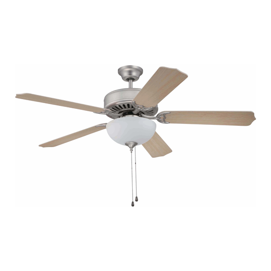
Pro Builder Fan
Installation Guide
For models:
C201
C202
C203
C204
C205
C206
C209
E192641
net weight of fans: 13.45 lb (6.1 kg)--C201, C202
15.15 lb (6.87 kg)--C203, C204
13.67 lb (6.2 kg)--C205, C206
13.23 lb (6 kg)--C209
READ THESE INSTRUCTIONS AND
Table of Contents:
Safety Tips. pg. 1
Unpacking Your Fan. pg. 2
Parts Inventory. pg. 2
Installation Preparation. pg. 3
Hanging Bracket Installation. pg. 3
Fan Assembly. pgs. 4 - 5
Wiring. pg. 5
Canopy Assembly. pg. 6
Blade Assembly. pg. 6
3- or 4-light Kit Assembly. pg. 9
Testing Your Fan. pg. 10
Troubleshooting. pg. 11
Warranty. pg. 11
Parts Replacement. pg. 11
SAVE THEM FOR FUTURE USE
PRINTED IN CHINA
Advertisement
Chapters
Table of Contents

Related Manuals for Craftmade Pro Builder


Summary of Contents for Craftmade Pro Builder
-
Page 1: Table Of Contents
READ THESE INSTRUCTIONS AND SAVE THEM FOR FUTURE USE Pro Builder Fan Installation Guide For models: C201 Table of Contents: Safety Tips. pg. 1 C202 Unpacking Your Fan. pg. 2 C203 Parts Inventory. pg. 2 Installation Preparation. pg. 3 C204 Hanging Bracket Installation. -
Page 2: Safety Tips
SAFETY TIPS. WARNING: To reduce the risk of electrical shock, turn off the electricity to the fan at the main fuse box or circuit panel before you begin the fan installation or before servicing the fan or installing accessories. READ ALL INSTRUCTIONS AND SAFETY INFORMATION CAREFULLY BEFORE INSTALLING YOUR FAN AND SAVE THESE INSTRUCTIONS. -
Page 3: Unpacking Your Fan
1. Unpacking Your Fan. Carefully open the packaging. Remove items from Styrofoam inserts. Remove motor housing and place on carpet or Styrofoam to avoid damage to finish. Do not discard fan carton or Styrofoam inserts should this fan need to be returned for repairs. -
Page 4: Installation Preparation
3. Installation Preparation. blade edge To prevent personal injury and damage, inches ensure that the hanging location allows the 7 feet (76cm) (2.13m) blades a clearance of 7 feet (2.13m) from the floor and 30in. (76cm) from any wall or 12ft - 20ft obstruction. -
Page 5: Fan Assembly. Pgs
stop pin 5. Fan Assembly. set screw Remove hanging ball from downrod provided by loosening set screw on hanging ball. Lower hanging ball hanging ball and remove stop pin and then slide hanging ball off of the downrod. [Refer to diagram 1.] diagram 1 Loosen yoke set screws and nuts at top of motor... -
Page 6: Wiring
5. Fan Assembly. (cont.) With the hanging bracket secured to the outlet box and able to support the fan, you are now ready to hang your fan. Grab the fan firmly with two hands. Slide downrod through opening in hanging bracket tab hanging bracket and let hanging ball rest on the hanging bracket. -
Page 7: Canopy Assembly
7. Canopy Assembly. hanging bracket Locate 2 screws on underside of hanging bracket and remove screw closest to the open screw end of the hanging bracket. Partially loosen the other screw. Lift canopy to hanging bracket. Place rounded part of slotted hole in canopy canopy over loosened screw in hanging bracket and push up. -
Page 8: Light Kit Assembly, 1-Light Options. Pgs
9. Light Kit Assembly, 1-light Options. *For Models C201 and C202 follow instructions on this page. *For Model C209, proceed to instructions on page 8. motor housing Remove 3 screws from switch housing cap (at top of light kit fitter). Locate BLUE (or BLACK) and WHITE wires in switch housing labeled FOR LIGHT KIT CONNECTION. - Page 9 9. Light Kit Assembly, 1-light Options. (cont.) (Only for model C209) motor housing Remove 3 screws from switch housing cap (at top of light kit fitter). Make sure pull chain is threaded through corresponding hole in light kit fitter. switch housing Locate BLUE (or BLACK) and WHITE wires in switch housing labeled FOR LIGHT KIT switch housing cap...
-
Page 10: 3- Or 4-Light Kit Assembly
10. Light Kit Assembly, 3- or 4-light Options. *For Models C203, C204, C205 and C206, motor housing follow instructions on this page. Remove 3 screws from top of light kit fitter. Locate BLUE (or BLACK) and WHITE wires switch molex housing in switch housing labeled FOR LIGHT KIT connections... -
Page 11: Testing Your Fan
11. Testing Your Fan. It is recommended that you test fan before finalizing installation. Restore power from circuit box and light switch (if applicable). Test fan speeds with the pull chain on the switch housing. Start at the OFF position (no blade movement). First pull will set the fan to HI. -
Page 12: Troubleshooting
Service at 1-800-486-4892 to arrange for return of fan. 1. Check wall switch to fan. Return fan, shipping prepaid, to Craftmade. We will repair 2. Verify that reverse switch is set completely in or ship you a replacement fan, and we will pay the return either direction. - Page 13 LEER ESTAS INSTRUCCIONES Y GUARDARLAS PARA UTILIZACION FUTURA Pro Builder Fan Guía de instalación Para modelos: Índice de materias: C201 Sugerencias de seguridad. Pág. 1 C202 Desempaquetado del ventilador. Pág. 2 C203 Inventario de piezas. Pág. 2 Preparación para la instalación. Pág. 3 C204 Instalación del soporte de montaje.
-
Page 14: Sugerencias De Seguridad. Pág
SUGERENCIAS DE SEGURIDAD. ADVERTENCIA: Para evitar la posibilidad de una descarga eléctrica, desconectar la corriente en la caja de fusibles principal o el interruptor protector antes de iniciar la instalación del ventilador o antes de repararlo o instalar accesorios. LEER TODAS LAS INSTRUCCIONES E INFORMACIÓN DE SEGURIDAD CUIDADOSAMENTE ANTES DE INSTALAR SU VENTILADOR Y GUARDAR ESTAS INSTRUCCIONES. -
Page 15: Desempaquetado Del Ventilador. Pág
1. Desempaquetado del ventilador. Abrir el empaque cuidadosamente. Sacar los artículos del embalaje. Sacar el motor y ponerlo en una alfombra o en el embalaje para evitar rayar el acabado. Guardar la caja de cartón o el empaquetamiento original en caso de que tenga que mandar el ventilador para alguna reparación. -
Page 16: Preparación Para La Instalación. Pág
3. Preparación para la instalación. borde del aspa Para prevenir daño corporal y otros daños, estar 76cm seguro de que el lugar en donde va a colgar el ventilador le permite un espacio libre de 2,13m 2,13m pulg.) (7 pies) entre las puntas de las aspas y el piso y (7 pies) 76cm (30 pulg.) entre las aspas y cualquier pared u otra obstrucción. -
Page 17: Ensamblaje Del Ventilador. Págs
perno de tope 5. Ensamblaje del ventilador. tornillo de fijación Quitar la bola que sirve para colgar del tubo provisto bola que aflojando el tornillo de fijación de la bola que sirve sirve para para colgar. Bajar la bola que sirve para colgar y sacar colgar el perno de tope y luego quitar la bola que sirve para colgar deslizándola. -
Page 18: Instalación Eléctrica. Pág
5. Ensamblaje del ventilador. (cont.) Ya que esté sujetado el soporte de montaje a la caja de salida y capaz de apoyar el ventilador, usted está listo para colgar el ventilador. Agarrar el ventilador firmemente con las dos manos. Deslizar el tubo por la abertura del soporte de montaje y dejar que se detenga la bola en el soporte parte saliente del de montaje. -
Page 19: Colocación De La Cubierta Decorativa. Pág
7. Colocación de la cubierta decorativa. soporte de Localizar los 2 tornillos en la parte inferior del montaje soporte de montaje y quitar el tornillo que está localizado más cerca del extremo abierto del tornillo soporte de montaje. Aflojar parcialmente el otro tornillo. - Page 20 9. Instalación del juego de luz, opciones de 1 sola luz. *Para Modelos C201 y C202, seguir las instrucciones de esta página. *Para Modelo C209, pasar a la página 8. Quitar los 3 tornillos de la cubierta de la caja de bastidor del motor encendido (en la parte superior del conectador para el juego de luz).
- Page 21 9. Instalación del juego de luz, opciones de 1 sola luz. (cont.) (Sólo para modelo C209) Quitar los 3 tornillos de la cubierta de la caja de encendido (en la parte superior del conectador bastidor para el juego de luz). Asegurarse de que la del motor cadena de encendido pase por el agujero correspondiente en el conectador para el juego...
- Page 22 10. Instalación del juego de luz, opción de 3 o 4 luces. *Para Modelos C203, C204, C205 y C206, seguir las instrucciones de esta página. bastidor del motor Quitar los 3 tornillos del conectador para el juego de luz. Localizar los cables AZUL (o NEGRO) y BLANCO en la caja de encendido con etiqueta que diga "FOR LIGHT caja de...
- Page 23 11. Verificación del funciona- miento del ventilador. Se le recomienda poner el ventilador a prueba antes de terminar la instalación. Regresar la corriente de electricidad en el cortacircuitos y encender el interruptor de la luz en la pared (si se aplica). Verificar las velocidades del ventilador con la cadena de encendido en la caja de encendido.
- Page 24 Soluciones: debido a defectos en los materiales o trabajo manual. Comunicarse con el Servicio al cliente de CRAFTMADE al 1. Inspeccionar el interruptor de pared del 1-800-486-4892 para acordar el reenvío del ventilador. ventilador.
Need help?
Do you have a question about the Pro Builder and is the answer not in the manual?
Questions and answers