
Subscribe to Our Youtube Channel
Related Manuals for Amana AXP520


Summary of Contents for Amana AXP520
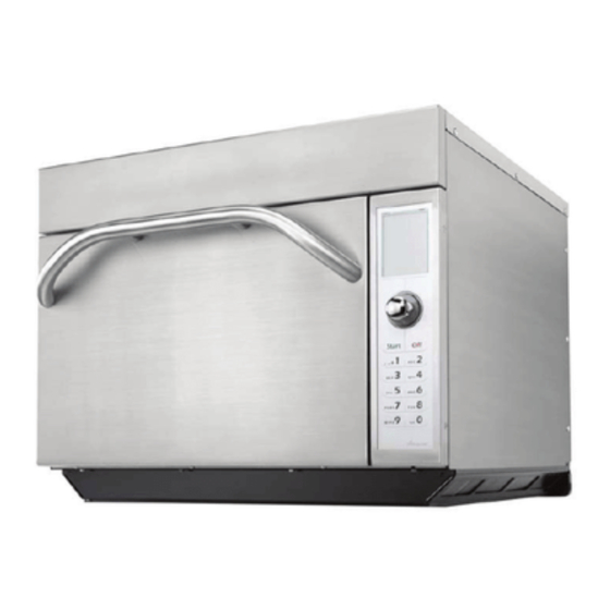
- Page 1 ______________ Service Manual High Speed Combination Oven AXP5201 MXP5201 P1333603M P1333604M 50 Hz 16400004 January 2010...
-
Page 2: Table Of Contents
TABLE OF CONTENTS IMPORTANT INFORMATION ....................1 IMPORTANT SAFETY INFORMATION ................2-4 Oven Specifications ......................5 Oven Construction ......................6-11 Oven Performance Test ....................12-13 Troubleshooting ......................14-17 Display Diagnostics ......................18 Service Test ........................19-26 Touch Screen Calibration .....................27 Component Test Procedures ..................28-29 Quick Start Reference Guide .................. -
Page 3: Important Information
Important Information Important Notices for Servicers and Consumers ACP will not be responsible for personal injury or property damage from improper service procedures. Pride and workmanship go into every product to provide our customers with quality products. It is possible, however, that during its lifetime a product may require service. -
Page 4: Important Safety Information
For additional product documentation or more detailed operating instructions visit: www.acpsolutions.com CONTACT INFORMATION Any questions or to locate an authorized Amana servicer, call ACP ComServ Service Support. – Inside the U.S.A. or Canada, call toll-free 866-426-2621. – Outside the U.S.A. and Canada, call 319-368-8195. -
Page 5: Important Safety Instructions
IMPORTANT SAFETY INSTRUCTIONS To reduce the risk of burns, electrical shock, fire, or personal injury when using WARNING electrical equipment, basic safety precautions should be followed. 1. READ all instructions before using equipment. 12. DO NOT immerse cord or plug in water. 13. Keep cord AWAY from HEATED surfaces. 2. READ AND FOLLOW the specific “PRECAUTIONS TO AVOID POSSIBLE 14. - Page 6 IMPORTANT SAFETY INSTRUCTIONS CAUTION To avoid risk of personal injury or property damage, observe the following safety instructions: General Use: 1. Do not use regular cooking thermometers in oven. pierced, steam escapes evenly. Most cooking thermometers contain mercury and 11. Do not heat sealed containers or plastic bags in may cause an electrical arc, malfunction, or damage oven.
-
Page 7: Oven Specifications
SPECIFICATIONS P1333603M AXP5201 Models MXP5201 P1333604M Power Source 230-240 VAC Voltage AC Amperage (Single Unit) 30 A 50 Hz Frequency Single Phase, 3 wire grounded Receptacle IEC 309 Plug IEC 309 Power Output – Microwave Nominal microwave energy (IEC705) 2200 Watts Minimum Temperature Rise (∆T) 22°F / 12°C Operating Frequency... -
Page 8: Oven Construction
OVEN CONSTRUCTION- OVEN CONSTRUCTION PANELS (TOP & SIDE) Right Outer Panel Door Air Filters Top Outer Panel Torx (T-15) Left Outer Panel Outercase Back Torx (T-15) - Page 9 OVEN CONSTRUCTION- OVEN CONSTRUCTION CONTROL PANEL ASSEMBLY Control Holder Display Board Touch Screen Display Knob Collar Knob Filter Board Touch Panel Assembly Bezel Data Key Board Data Key Board Holder Data Key Plug Caution: Do not handle touch screen display by the sides.
-
Page 10: Convection Motor
OVEN CONSTRUCTION- OVEN CONSTRUCTION Circuit Boards Power Relay Limiter Triac Thermocouple Temp Sensor (RTD) Cooling Fans Convection Motor Cavity TCO Convection Motor Main Board *Relay Monitor Board *Power Relay Temp Sensor Snubber (RTD Radiant) Power Supply Board Thermocouple (24 VDC) Limiter (Limiter) Cavity... - Page 11 OVEN CONSTRUCTION- OVEN CONSTRUCTION HV Transformers Magnetrons Fuses Sensor Triac’s Magnetron TCO’s Capacitor / Diodes Line Filter Small Fuses F2,F3,F4 (12 amp) High Voltage Transformers Temp Sensor F2 - Convection Motor (RTD Convection) F3 - Magnetron # 1 F4 - Magnetron # 2 Switch (Primary) Capacitor...
- Page 12 OVEN CONSTRUCTION- Oven Switch Replacement & Interlock Switch Adjustment Switch Adjustment Lever Attach Ohm-Meter to Wire Harness Connectors Adjustment Figure 1 Slide Adjustment Switch Test: Screws When the door is opened or closed, the left door hinge activates the secondary / monitor switches. 1.
-
Page 13: Oven Construction
OVEN CONSTRUCTION- Antenna Motor Gear Assembly Antenna Rivet, Plastic See Detail Below *Note: Plastic Rivet cannot be reused. Antenna Motor Rivet, *Plastic Gear Assembly Alignment Arrows Antenna... -
Page 14: Oven Performance Test
OVEN PERFORMANCE TEST Note: To run Oven Performance Test the, OVEN CAVITY mUST BE AT ROOm TEmPERATURE, and the display must read mICROWAVE ONLY mode. See below using oven as a microwave oven. If mICROWAVE ONLY is not in display you must go to User Options and activate mICROWAVE ONLY option. Changing User Options: 1. Oven must be OFF. KEYPAD 2. Press and hold Pad "2" for 5 seconds. 3. Rotate dial to highlight: ALLOW mICROWAVE ONLY mode. 4. Press SAVE. PREHEAT MENU USING OVEN AS A MICROWAVE OVEN °C This option is only available if the oven cavity temperature is less than 93 245 °C When user option MICROWAVE ONLY is set as a default, the MICROWAVE ONLY button appears on the PREHEAT MENU. - Page 15 OVEN PERFORMANCE TEST All Amana and Menumaster microwave oven power outputs are rated using the IEC705 standards. Using the IEC705 test method requires precision measurements and equipment that is not practical to be performed in the field. Using the test shown below will indicate if the oven performance is satisfactory.
-
Page 16: Troubleshooting
Troubleshooting POWER UP CONDITION PLUG OVEN IN (NORMAL DISPLAY) PREHEAT TEMP = 270 C PRESS TO PREHEAT 1. No Line Voltage CHANGE 2. Inoperative Power Cord PROGRAM TEMP 3. Inoperative Fuse 4. Inoperative Touch Screen 5. Inoperative Main Control Board 6. - Page 17 Troubleshooting PREHEAT CONDITION Touch PRESS TO PREHEAT On Touch Screen Push Knob In (NORMAL DISPLAY) OVEN PREHEATING PREHEAT TEMP = 270 C Inoperative Display Board Inoperative Touch Screen Indicates Rising Temperature CHANGE PROGRAM TEMP 1. Inoperative Thermocouple 2. Inoperative Radiant Heater 3.
-
Page 18: Microwave Condition
Troubleshooting MICROWAVE CONDITION SERVICE TEST 1. Press Off Pad Repeatedly Until Press to Preheat Appears 2. Press Hidden Pad 3. Press Pads 1-3-5-7-9 (NORMAL DISPLAY) SERVICE MODE OVEN INFORMATION DISPLAY VERSION: 0.39 MAIN VER: 0.46 EE 0.3 DOOR CYCLES 20,156 TUBE HRS: 2156 EE 255 NEXT PREV... - Page 19 Troubleshooting OPERATIONAL CODES During oven operation the display may indicate one of the following: 1. When you press the pad/ knob to preheat the oven the display indicates. 2. During cooking, the oven the display indicates. CALL SERVICE 1. Unplug / plug oven in 2.
-
Page 20: Display Diagnostics
Display Diagnostics ERROR CODES: DISPLAY DESCRIPTION CORRECTIVE ACTION Touch Panel Replace Touch Panel Touch Panel Replace Touch Panel Temp Sensor (RTD) (open) Replace Temp Sensor Temp Sensor (RTD) (shorted) Replace Temp Sensor Temp Sensor (RTD) (out of range) Replace Temp Sensor Thermocouple (RTD) (open) Replace Thermocouple Thermocouple (RTD) (shorted) -
Page 21: Service Test
AXP20 Service Test Service Test Access to Service Mode Screen While at the Main Screen, press the following sequence on the keypad: NOTE: The “MICROWAVE ONLY” button may or may not be present. 1. Press OFF pad until PRESS TO PREHEAT appears. - Page 22 Service Test Manual Operation of Magnetrons #1 & #2 Screen This screen will allow operation of Magnetron #1 and #2 together and show the number of amps being drawn. NEXT TEST: Press this pad to go to the next Service Mode Test PREV TEST: Press this pad to go to the previous Service Mode Test TURN ON: This pad will toggle between...
- Page 23 Service Test Manual Operation of Magnetron #2 Screen This screen will allow operation of Magnetron #2 and show the number of amps being drawn. NEXT TEST: Press this pad to go to the next Service Mode Test PREV TEST: Press this pad to go to the previous Service Mode Test TURN ON: This pad will toggle between turning the magnetron on and off.
- Page 24 Service Test Radiant Heater Screen This screen will allow operation of the radiant heater and show the number of amps being drawn. NEXT TEST: Press this pad to go to the next Service Mode Test PREV TEST: Press this pad to go to the previous Service Mode Test TURN ON: This pad will toggle between turning the heater on and off.
- Page 25 Service Test Convection Fan – High Speed Screen This screen will allow operation of the convection fan at a high speed and show the number of amps being drawn. NEXT TEST: Press this pad to go to the next Service Mode Test PREV TEST: Press this pad to go to the previous Service Mode Test TURN ON: This pad will toggle between...
- Page 26 Service Test Antenna Motor Screen This screen will allow operation of the antenna motor show the number of amps being drawn. NEXT TEST: Press this pad to go to the next Service Mode Test PREV TEST: Press this pad to go to the previous Service Mode Test TURN ON: This pad will toggle between turning the antenna motor on and off.
- Page 27 Service Test Memory / Network Status Screen This screen will show which memory chips are present and if the oven is hooked up to an external network. NEXT TEST: Press this pad to go to the next Service Mode Test PREV TEST: Press this pad to go to the previous Service Mode Test CANCEL: Press this pad to return to the...
-
Page 28: Service Test
Service Test Error History Screen This screen will show the previous error codes that have occurred in the oven. NEXT TEST: Press this pad to go to the next Service Mode Test PREV TEST: Press this pad to go to the previous Service Mode Test SCROLL: This pad will advance through the history of the error codes. -
Page 29: Touch Screen Calibration
Calibration Touch Screen Calibration To calibrate the touch screen perform the following steps. The oven must be plugged In. Stand-by screen must be in the Display. Press the Hidden Pad. Standby Screen □ □ Hidden Pad Press Pads 4, 5, 6. Press Directly ON small Square in the Display. -
Page 30: Component Testing Procedures
Component Testing Procedures WARNING To avoid risk of electrical shock, personal injury or death; disconnect power to oven and discharge capacitor before servicing, unless testing requires power. Illustration Component Test Results Thermal cutout Disconnect all wires from TCO. Measure resistance across terminals. Control TCO .......... - Page 31 Component Testing Procedures WARNING To avoid risk of electrical shock, personal injury or death; disconnect power to oven and discharge capacitor before servicing, unless testing requires power. Illustration Component Test Results Transformer Discharge Capacitor Remove all wires from terminals. Measure resistance from: 230 to COM..........
-
Page 32: Quick Start Reference Guide
Quick Start Reference Guide High Speed Commercial Combination Oven Refer to Product Safety Manual for Safety Statements. Complete Owner’s Manual available online Cooking with Pre- Oven Controls programmed Pads o cook food using pre-programmed menu he oven touch screen displays items menu options. -
Page 33: Quick Start Reference Guide
Quick Start Reference Guide High Speed Commercial Combination Oven MENU ACCESSING THE PROGRAM MENU MENU Pasta-Pizza 1. To access the PROGRAm mENU, select Appet-Side the BACK button on the main menu screen. Meats Seaf-Sub Pasta-Pizza Appet-Side Dess-Soup Breakfast Push MANUAL BACK Seaf-Sub Meats COOK 2. Then select PROGRAm from the Dess-Soup Breakfast READY screen. - Page 34 Quick Start Reference Guide High Speed Commercial Combination Oven ADDING ITEM TO ITEM MENU 1. Select NEW from the PROGRAm mENU.to add a new item or EDIT to edit item. Push 2. Select category you wish to change from mAIN mENU and ITEm GROUP menus. 3. At the ITEm mENU, rotate dial until until item to be added or changed is highlighted and press dial. The confirm screen will appear and ask you to confirm the change you’re making. Touch CREATE or press knob CREATING NEW ITEM GROUP to CONFIRm OVERWRITE. Note - When editing an item the CONFIRm OVERWRITE screen does not appear. Misc MENU Appet-Side CONFIRM Tater Tots 6oz The cooking program menu will appear...
-
Page 35: Quick Start Reference Guide
Quick Start Reference Guide High Speed Commercial Combination Oven Refer to Product Safety Manual for Safety Statements. Complete Owner’s Manual available online KEYPAD Changing User Options There are several option you can change to customize the operation of the oven for your business. The table below shows these options;... -
Page 36: Ez Card Programming
AXP5201 / MXP5201 EZCard Programming To program the oven using the EZCard: Oven must be in Standby mode (Preheat must be OFF) 1. Open protective cover from bottom of keypad. 2. Insert the EZCard into the slot located below the vertical keypad. Note: The EZCard can be inserted forwards or backwards. -
Page 37: Wiring Diagram
Wiring Diagram - AXP5201 P1333603M, MXP5201 P1333604M SHIELDED CABLE... -
Page 38: Schematic Diagram
Schematic Diagram - AXP5201 P1333603M, MXP5201 P1333604M LINE FILTER J1-1 J1-3 J2-6,7 J2-8 DATA J2-1 +24VDC PORT PORT OVEN CAVITY POWER SUPPLY J1-1 J1-3 J10-1 +24VDC KEYPAD DATAKEY TACH J10-2 CONTROL BOARD J10-3 J10-4 TOUCHSCREEN DISPLAY DISPLAY BOARD FILTER RADIANT CONVECTION BOARD ST1-1... - Page 39 16400004 50 Hz High Speed Combi – AXP520 January 2010...
Need help?
Do you have a question about the AXP520 and is the answer not in the manual?
Questions and answers