Cisco UCS C200 Installation And Service Manual
Hide thumbs
Also See for UCS C200:
- Installation and service manual (108 pages) ,
- Configuration manual (88 pages) ,
- Setup (10 pages)
Table of Contents
Advertisement
S e n d d o c u m e n t c o m m e n t s t o u c s - d o c f e e d b a c k @ c i s c o . c o m
Cisco UCS C200 Server
Installation and Service Guide
Covers UCS C200 Server Generations M1 and M2
January 26, 2011
Americas Headquarters
Cisco Systems, Inc.
170 West Tasman Drive
San Jose, CA 95134-1706
USA
http://www.cisco.com
Tel: 408 526-4000
800 553-NETS (6387)
Fax: 408 527-0883
Text Part Number: OL-20732-02
Advertisement
Table of Contents

Related Manuals for Cisco UCS C200


Summary of Contents for Cisco UCS C200
- Page 1 S e n d d o c u m e n t c o m m e n t s t o u c s - d o c f e e d b a c k @ c i s c o . c o m Cisco UCS C200 Server Installation and Service Guide Covers UCS C200 Server Generations M1 and M2 January 26, 2011 Americas Headquarters Cisco Systems, Inc.
- Page 2 Modifications to this product not authorized by Cisco could void the FCC approval and negate your authority to operate the product. The Cisco implementation of TCP header compression is an adaptation of a program developed by the University of California, Berkeley (UCB) as part of UCB’s public domain version of the UNIX operating system.
-
Page 3: Table Of Contents
Determining the iFlash32 Utility Version and Build 2-18 Recovering a Corrupted BIOS 2-19 Using the BIOS Recovery Jumper J1E5 2-19 Motherboard Jumpers 2-20 Clearing the CIMC Admin Password Using Jumper J45 2-21 Cisco UCS C200 Server Installation and Service Guide OL-20732-02... - Page 4 Replacing a PCIe Riser Card Assembly 3-24 Replacing a PCIe Card (Network Adapters) 3-25 Special Considerations for the Cisco UCS P81E Virtual Interface Card (N2XX-ACPCI01) 3-27 How to Identify Which Power Supply Model is in Your Server 3-28 Replacing a PCIe Card (Mass Storage Controllers)
- Page 5 For More Information Installation for Cisco UCS Integration A P P E N D I X Installing a Release 1.2(2) or Later Server for Cisco UCS Integration Required Items Procedure Upgrading a Server Earlier Than Release 1.2(2) for Cisco UCS Integration...
- Page 6 S e n d d o c u m e n t c o m m e n t s t o u c s - d o c f e e d b a c k @ c i s c o . c o m Cisco UCS C200 Server Installation and Service Guide...
-
Page 7: Preface
This preface describes the audience, organization, and conventions of the Cisco UCS C200 Server Installation and Service Guide. It also provides information on how to obtain related documentation. This guide covers UCS C200 Server Generations M1 and M2. Differences between the generations are noted in text. -
Page 8: Conventions
Gebruik het nummer van de verklaring onderaan de waarschuwing als u een vertaling van de waarschuwing die bij het apparaat wordt geleverd, wilt raadplegen. BEWAAR DEZE INSTRUCTIES Cisco UCS C200 Server Installation and Service Guide viii OL-20732-02... - Page 9 å forhindre ulykker. Bruk nummeret i slutten av hver advarsel for å finne oversettelsen i de oversatte sikkerhetsadvarslene som fulgte med denne enheten. TA VARE PÅ DISSE INSTRUKSJONENE Cisco UCS C200 Server Installation and Service Guide OL-20732-02...
- Page 10 Använd det nummer som finns i slutet av varje varning för att hitta dess översättning i de översatta säkerhetsvarningar som medföljer denna anordning. SPARA DESSA ANVISNINGAR Cisco UCS C200 Server Installation and Service Guide OL-20732-02...
- Page 11 Brug erklæringsnummeret efter hver advarsel for at finde oversættelsen i de oversatte advarsler, der fulgte med denne enhed. GEM DISSE ANVISNINGER Cisco UCS C200 Server Installation and Service Guide OL-20732-02...
- Page 12 S e n d d o c u m e n t c o m m e n t s t o u c s - d o c f e e d b a c k @ c i s c o . c o m Cisco UCS C200 Server Installation and Service Guide...
-
Page 13: Obtaining Documentation And Submitting A Service Request
Obtaining Documentation and Submitting a Service Request For information on obtaining documentation, submitting a service request, and gathering additional information, see the monthly What’s New in Cisco Product Documentation, which also lists all new and revised Cisco technical documentation, at: http://www.cisco.com/en/US/docs/general/whatsnew/whatsnew.html... - Page 14 S e n d d o c u m e n t c o m m e n t s t o u c s - d o c f e e d b a c k @ c i s c o . c o m Cisco UCS C200 Server Installation and Service Guide...
-
Page 15: Chapter 1 Overview
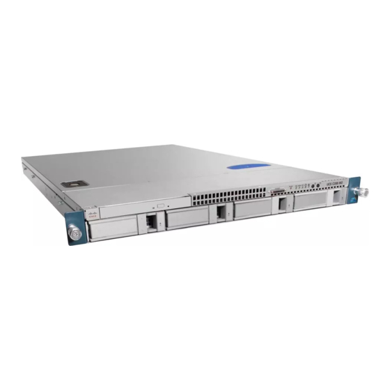
C H A P T E R Overview The Cisco UCS C200 Server, which is a part of the Cisco UCS C-Series Rack-Mount server family, is designed to operate in a wide range of data center environments, including those environments that use the Cisco Unified Computing System, Cisco Nexus family products, and discrete Ethernet and Fibre Channel switches from Cisco and third parties. - Page 16 Serial connector (DB9) Video connector (DB15 VGA) 10/100/1000 Gigabit Ethernet ports (two) Low-profile PCIe card slot Standard-profile PCIe card slot The Cisco UCS C200 server has the following components and features: Table 1-1 Hardware Features of the Server Feature or Component...
- Page 17 6. PCIe = peripheral component interconnect express 7. VGA = video graphics array 8. USB = universal serial bus 9. KVM = keyboard, video, mouse Appendix A, “Technical Specifications” for more physical, environmental, and power details. Cisco UCS C200 Server Installation and Service Guide OL-20732-02...
- Page 18 S e n d d o c u m e n t c o m m e n t s t o u c s - d o c f e e d b a c k @ c i s c o . c o m Cisco UCS C200 Server Installation and Service Guide...
-
Page 19: Updating The Cimc Firmware
Statement 1071 Only trained and qualified personnel must be allowed to install, replace, or service this equipment. Warning Statement 1030 Cisco UCS C200 Server Installation and Service Guide OL-20732-02... -
Page 20: Unpacking And Inspecting The Server
Effect of damage on the installation • Figure 2-1 Shipping Box Contents Reset Console PSU MEM CPU UCS C200 Server Drivers and Utilities disc Power cord (optional, up to two) Documentation KVM cable Cisco UCS C200 Server Installation and Service Guide OL-20732-02... -
Page 21: Preparing For Installation
Avoid UPS types that use ferroresonant technology. These UPS types can become unstable with systems Caution such as the Cisco UCS, which can have substantial current draw fluctuations from fluctuating data traffic patterns. Cisco UCS C200 Server Installation and Service Guide... -
Page 22: Rack Requirements
Cisco. Required Equipment The slide rails supplied by Cisco Systems do not require any tools for installation, but you might want to use a tape measure and level to help level the slide rails during installation. - Page 23 You can install two of these screws on each side of the server to more permanently attach the mounting brackets to each side of the server, but they are not required. Cisco UCS C200 Server Installation and Service Guide OL-20732-02...
- Page 24 Fit the two-hole slotted bracket over the two pegs inside the slide rail. Attach the outermost CMA attachment clip (item 6) onto the CMA flange that is on the left slide rail. Cisco UCS C200 Server Installation and Service Guide OL-20732-02...
- Page 25 Innermost CMA attachment clip Two-hole slotted bracket on end of CMA Outermost CMA attachment clip length-adjustment slider Continue with the “Connecting and Powering On the Server (Standalone Mode)” section on page 2-8. Step 5 Cisco UCS C200 Server Installation and Service Guide OL-20732-02...
-
Page 26: Initial Server Setup
Cisco Integrated Management Interface (CIMC). If you want to use the 10/100 management ports or a Cisco network adapter card port to access the CIMC, you must first connect to the server and change the NIC mode as described in Step 3 of the following procedure. - Page 27 Shared LOM (default)—The two 1Gb Ethernet ports are used to access the CIMC. This is the – factory default setting, along with Active-active NIC redundancy and DHCP enabled. Cisco Card—The ports on an installed Cisco network adapter card are used to access the CIMC. – You have to select a NIC redundancy and IP setting.
- Page 28 The links to these documents are in the C-Series documentation roadmap: http://www.cisco.com/go/unifiedcomputing/c-series-doc To install or replace hardware components, see the “Maintaining the Server” section on page 3-1. Cisco UCS C200 Server Installation and Service Guide 2-10 OL-20732-02...
-
Page 29: Defining Static Network Settings Using A Script File
After the server has been assigned an IP address, you can use that address to access the service processor’s GUI or CLI management system. See the Cisco UCS C-Series Rack-Mount Server Configuration Guide or the Cisco UCS C-Series Rack-Mount Server CLI Configuration Guide. Cisco UCS C200 Server Installation and Service Guide 2-11 OL-20732-02... -
Page 30: Nic Modes And Nic Redundancy Settings
Shared LOM (default)—The two 1Gb Ethernet ports are used to access the CIMC. This is the factory default setting, along with Active-active NIC redundancy and DHCP enabled. Cisco Card—The ports on an installed Cisco network adapter card are used to access the CIMC. You •... -
Page 31: Configuring Bios Settings And Updating Bios Firmware
Follow the instructions on the Exit menu screen to save your changes and exit the setup utility (or Press Step 6 F10). You can exit without saving changes by pressing Esc. Cisco UCS C200 Server Installation and Service Guide 2-13 OL-20732-02... -
Page 32: Overview Of The Bios Setup Pages
Lists system errors with descriptions and severity Exit • Options that you can use to exit while either saving or discarding changes • Options to save current values as a user default, or load default values Cisco UCS C200 Server Installation and Service Guide 2-14 OL-20732-02... -
Page 33: Updating The Bios Firmware
Use the following procedure to update the BIOS firmware by using the EFI interface. Instructions are included for using local media or a virtual device. Download the BIOS update package from Cisco.com and extract it to a temporary location. Step 1 To find the downloads for your server, see the following URL, then click Unified Computing, log in, and then click Cisco UCS C-Series Rack-Mount Servers. - Page 34 Windows_x86 Windows_x64 Cisco.com and extract it to a temporary folder on the server’s host OS. To find the downloads for your server, see the following URL, then click Unified Computing, log in, and then click Cisco UCS C-Series Rack-Mount Servers.
- Page 35 Boot the server using a hard drive that has the Linux host OS installed. Step 1 Download the BIOS update package for Linux and the C200 server from Cisco.com and extract it to a Step 2 temporary folder on the server’s host OS.
-
Page 36: Iflash32 Utility Command Options
For Windows: iflash /i • For Linux: iflash -i • The output should be similar to the following: Iflash32 BIOS Update Utility Ver 1.1 Build 3 Copyright (C) 2009-2010 Cisco Systems Inc. Cisco UCS C200 Server Installation and Service Guide 2-18 OL-20732-02... -
Page 37: Recovering A Corrupted Bios
Press the Power button to shut down the server to standby power mode, and then remove AC power cords from the server to remove all power. Step 13 Remove the top cover from the server. Cisco UCS C200 Server Installation and Service Guide 2-19 OL-20732-02... -
Page 38: Motherboard Jumpers
Clearing the BIOS Admin Password Using Jumper J1E4, page 2-23 Figure 2-5 Service Jumper Locations Jumper J1E6 (clear CMOS) Jumper J45 (clear CIMC password) Jumper J1E5 (BIOS recovery) Jumper J1E4 (clear BIOS password) Cisco UCS C200 Server Installation and Service Guide 2-20 OL-20732-02... -
Page 39: Clearing The Cimc Admin Password Using Jumper J45
Replace the top cover, replace the server in the rack, replace power cords and any other cables, then Step 11 power on the server by pressing the Power button. Cisco UCS C200 Server Installation and Service Guide 2-21 OL-20732-02... - Page 40 Replace the top cover, replace the server in the rack, replace power cords and any other cables, then Step 11 power on the server by pressing the Power button. Cisco UCS C200 Server Installation and Service Guide 2-22 OL-20732-02...
- Page 41 If you do not remove the jumper, the password is cleared every time that you power-cycle the server. Replace top cover, replace the server in the rack, replace power cords and any other cables, then power Step 11 on the server by pressing the Power button. Cisco UCS C200 Server Installation and Service Guide 2-23 OL-20732-02...
-
Page 42: Updating The Cimc Firmware
The server uses CIMC firmware obtained from and certified by Cisco. After you have downloaded a CIMC firmware image from Cisco, you can use it to update the firmware on your server. Cisco also provides release notes with each firmware image. -
Page 43: Status Leds
This section describes the locations and interpretations of LEDs on the server that can provide status and troubleshooting information. This section includes the following topics: Front Panel LEDs, page 3-2 • • Rear Panel LEDs, page 3-3 Cisco UCS C200 Server Installation and Service Guide OL-20732-02... -
Page 44: Status Leds
Off—The server is powered off or in standby power mode. • Green, blinking—The server is communicating with the network in • main power mode. The blink rate is faster as network activity increases. Cisco UCS C200 Server Installation and Service Guide OL-20732-02... -
Page 45: Rear Panel Leds
10/100 Ethernet link status LED 10/100/1000 Gigabit Ethernet speed LED 10/100/1000 Gigabit Ethernet link status LED Table 3-2 describes the possible states and interpretations for the LEDs that are shown in Figure 3-2. Cisco UCS C200 Server Installation and Service Guide OL-20732-02... - Page 46 Link status amber + speed solid green—A half-duplex, 100-Mbps • link is present. Link status off + speed blinking green—A full-duplex, • 10-Mbps link is present. Link status amber + speed blinking green—A full-duplex, • 100-Mbps link is present. Cisco UCS C200 Server Installation and Service Guide OL-20732-02...
- Page 47 Link status off + speed blinking green—A full-duplex, 10-Mbps link is present. Link status green + speed blinking green—A full-duplex, • 100-Mbps link is present. Link status amber + speed blinking green—A full-duplex, • 1000-Mbps link is present. Cisco UCS C200 Server Installation and Service Guide OL-20732-02...
-
Page 48: Preparing For Component Installation
• Configuration Guide or the Cisco UCS C-Series Rack-Mount Server CLI Configuration Guide. Use the Power button on the server front panel. To use the Power button, follow these steps: • Cisco UCS C200 Server Installation and Service Guide OL-20732-02... -
Page 49: Removing And Replacing The Server In A Rack
2-6), and then continue pushing the server in evenly until its front flanges touch the rack posts. Tighten the thumbscrews on each flange to secure the server to the rack posts. Cisco UCS C200 Server Installation and Service Guide OL-20732-02... -
Page 50: Removing And Replacing The Server Top Cover
Use a Number 2 Phillips head screwdriver to remove the two screws that secure the top cover (Generation M1 only). The UCS C200 Generation M2 server does not have cover screws. Note Press down on the release button and use the nonslip pad to push the cover toward the rear about one inch, until you feel it stop sliding. -
Page 51: Replaceable Component Locations
PCIe card connector on riser card (with low-profile slot) Socket for trusted platform module (TPM) 10 Socket for LSI 1064-based mezzanine card 11 Power supplies (up to two, accessible through rear bays) Cisco UCS C200 Server Installation and Service Guide OL-20732-02... -
Page 52: Installing Or Replacing Components
Replacing a PCIe Riser Card Assembly, page 3-24 • Replacing a PCIe Card (Network Adapters), page 3-25 • Replacing a PCIe Card (Mass Storage Controllers), page 3-28 • Installing a Mezzanine Card, page 3-33 • Cisco UCS C200 Server Installation and Service Guide 3-10 OL-20732-02... -
Page 53: Installing Hard Drives
With the ejector lever still open, push the sled into the drive bay until you feel the drive stop against the backplane. Press the ejector lever flat until the lock clicks into place. Cisco UCS C200 Server Installation and Service Guide 3-11 OL-20732-02... -
Page 54: Installing Power Supplies
Remove the power cord from the power supply that you are replacing. Push the release lever toward the center of the power supply or blanking panel and pull on the handle to disengage the supply from the backplane (see Figure 3-6). Cisco UCS C200 Server Installation and Service Guide 3-12 OL-20732-02... -
Page 55: Installing A Fan Tray
BBU. Remove the three screws that secure the BBU to the bracket on the fan tray and set the BBU aside. See the “Special Installation Instructions For the LSI MegaRAID Battery Backup Unit” section on page 3-30 for more information. Cisco UCS C200 Server Installation and Service Guide 3-13 OL-20732-02... - Page 56 Replace the server in the rack, replace power cords and any other cables, and then power on the server by pressing the Power button. Figure 3-7 Removing and Replacing a Fan Tray Securing screw (one on each end) Fan tray with battery unit bracket Fan tray connector Cisco UCS C200 Server Installation and Service Guide 3-14 OL-20732-02...
-
Page 57: Installing Dimms
The DIMM slots on the right (channels A, B, and C) are associated with CPU1, while the DIMM slots on the left (channels D, E, and F) are associated with CPU2. Cisco UCS C200 Server Installation and Service Guide 3-15 OL-20732-02... - Page 58 CPU. Figure 3-9 Logical Representation of Channels and Banks Channel D Channel A Channel E Channel B CPU2 CPU1 Channel F Channel C Cisco UCS C200 Server Installation and Service Guide 3-16 OL-20732-02...
-
Page 59: Dimm Installation Procedure
Push down on the ejector levers at both ends of the DIMM slot. Grasp the DIMM by its top corners and remove it from the server. Place the DIMM on an antistatic mat or in antistatic packaging. Cisco UCS C200 Server Installation and Service Guide 3-17 OL-20732-02... - Page 60 Replace the server in the rack, replace power cords and any other cables, and then power on the server by pressing the Power button. Figure 3-10 Removing and Replacing Memory Modules DIMM slots (twelve) DIMM slot ejector lever (two on each slot) Alignment key in DIMM slot Cisco UCS C200 Server Installation and Service Guide 3-18 OL-20732-02...
-
Page 61: Installing Cpus And Heatsinks
Replace the air baffle and the top cover. Replace the server in the rack, replace power cords and any other cables, and then power on the server by pressing the Power button. Cisco UCS C200 Server Installation and Service Guide 3-19 OL-20732-02... - Page 62 S e n d d o c u m e n t c o m m e n t s t o u c s - d o c f e e d b a c k @ c i s c o . c o m Figure 3-11 Removing and Replacing CPUs and Heatsinks Captive heatsink screws (two per CPU) CPU cover plate CPU socket alignment keys CPU socket latch Cisco UCS C200 Server Installation and Service Guide 3-20 OL-20732-02...
-
Page 63: Installing A Motherboard Cmos Battery
Ensure that the retaining clip clicks over the top of the battery. Replace the top cover. Replace the server in the rack, replace power cords and any other cables, and then power on the server by pressing the Power button. Cisco UCS C200 Server Installation and Service Guide 3-21 OL-20732-02... -
Page 64: Installing A Trusted Platform Module
TPM to press the connector into the socket. Replace the securing screw that holds the TPM to the motherboard standoff. Replace the PCIe riser card assembly. Cisco UCS C200 Server Installation and Service Guide 3-22 OL-20732-02... - Page 65 You can reboot the server by pressing the Power button on the server; by selecting Macros > Ctrl-Alt-Del on the Cisco KVM Console window menu bar; or by selecting Power Cycle Server on the Server Summary tab of the CIMC GUI.
-
Page 66: Replacing A Pcie Riser Card Assembly
Replace the screw that secures the assembly to the chassis. Replace the top cover. Replace the server in the rack, replace power cords and any other cables, and then power on the server by pressing the Power button. Cisco UCS C200 Server Installation and Service Guide 3-24 OL-20732-02... -
Page 67: Replacing A Pcie Card (Network Adapters)
For mass storage controller PCIe cards, see the “Replacing a PCIe Card (Mass Storage Controllers)” section on page 3-28. If you are installing a Cisco UCS P81E Virtual Interface Card (N2XX-ACPCI01), there are prerequisite Note considerations. See Special Considerations for the Cisco UCS P81E Virtual Interface Card (N2XX-ACPCI01), page 3-27. - Page 68 Replace the screw that secures the riser card assembly to the chassis. Replace the top cover. Replace the server in the rack, replace power cords and any other cables, and then power on the server by pressing the Power button. Cisco UCS C200 Server Installation and Service Guide 3-26 OL-20732-02...
-
Page 69: Special Considerations For The Cisco Ucs P81E Virtual Interface Card (N2Xx-Acpci01)
This server supports installation of one of these cards. • This card is supported only in PCIe slot 2 of this server. This card must be installed in PCIe slot 2 to use the Cisco Card NIC mode (see Figure 3-15 on Note page 3-27). -
Page 70: How To Identify Which Power Supply Model Is In Your Server
R2X0-PSU2-650W-SB has a sticker with the number 650W-SB; the old power supply has no sticker. Use the Cisco Integrated Management Controller (CIMC) GUI to view the power supply model: Use a browser to connect to CIMC using the CIMC IP address. - Page 71 Replace the screw that secures the riser card assembly to the chassis. Replace the top cover. Replace the server in the rack, replace power cords and any other cables, and then power on the server by pressing the Power button. Cisco UCS C200 Server Installation and Service Guide 3-29 OL-20732-02...
-
Page 72: Special Installation Instructions For The Lsi Megaraid Battery Backup Unit
Replace the three securing screws that hold the BBU to the BBU bracket. Replace the cable connector to socket J2 on the underside of the BBU. Cisco UCS C200 Server Installation and Service Guide 3-30 OL-20732-02... - Page 73 Connect the cable from the BBU to the socket on the adapter. Note Be careful to align the arrow-mark on the cable connector with the arrow-mark on the socket to avoid damaging the connector pins. Cisco UCS C200 Server Installation and Service Guide 3-31 OL-20732-02...
-
Page 74: Identifying Which Cards Are Installed In Your Server
On the Main page of the BIOS Setup utility, set Quiet Boot to Disabled. This allows non-default prompts Step 3 and POST messages to display during bootup instead of the Cisco logo screen. Press F10 to save your changes and exit the utility. -
Page 75: Installing A Mezzanine Card
Reconnect the cable harness to the connector on the top of the mezzanine card. Replace the top cover. Replace the server in the rack, replace power cords and any other cables, and then power on the server by pressing the Power button. Cisco UCS C200 Server Installation and Service Guide 3-33 OL-20732-02... - Page 76 S e n d d o c u m e n t c o m m e n t s t o u c s - d o c f e e d b a c k @ c i s c o . c o m Figure 3-19 Removing and Replacing a Mezzanine Card Mezzanine card retaining posts (three) Mezzanine card Cisco UCS C200 Server Installation and Service Guide 3-34 OL-20732-02...
-
Page 77: Appendix
S e n d d o c u m e n t c o m m e n t s t o u c s - d o c f e e d b a c k @ c i s c o . c o m A P P E N D I X Technical Specifications This appendix lists the technical specifications for the Cisco UCS C200 server and includes the following sections: Physical Specifications, page A-1 •... -
Page 78: Environmental Specifications
Power supply output voltage Main power: 12 VDC Standby power: 5 VDC You can get more specific power information for your exact server configurationby using the Cisco UCS Power Calculator: http://www.cisco.com/assets/cdc_content_elements/flash/dataCenter/cisco_ucs_power_calculator/ Cisco UCS C200 Server Installation and Service Guide... -
Page 79: Appendix
USB ports for a keyboard and mouse. With this cable, you can create a direct connection to the operating system and the BIOS running on the server. This server supports the following Cisco components and part numbers. Supported Components... -
Page 80: Appendix B Cable And Power Cord Specification
Power Cord, 250 VAC 10 A CEI 23-16 Plug Italy CAB-9K10A-SW Figure B-9 Power Cord, 250 VAC 10 A MP232 Plug Switzerland CAB-9K10A-UK Figure B-10 Power Cord, 250 VAC 10 A BS1363 Plug (13 A fuse) United Kingdom Cisco UCS C200 Server Installation and Service Guide OL-20732-02... -
Page 81: Ac Power Cord Illustrations
Length: 8.2 ft Plug: EL 219 (IRAM 2073) Connector: EL 701 (IEC60320/C13) Figure B-3 CAB-9K10A-AU Cordset rating: 10 A, 250 V/500V Length: 2500mm Connector: Plug: EL 701C EL 206 (IEC 60320/C15) A.S. 3112-2000) Cisco UCS C200 Server Installation and Service Guide OL-20732-02... - Page 82 Cordset rating: 10A/16 A, 250 V Length: 8 ft 2 in. (2.5 m) Plug: M2511 Connector: VSCC15 Figure B-6 SFS-250V-10A-ID Cordset rating 16A, 250V Plug: (2500mm) EL 208 Connector: EL 701 Cisco UCS C200 Server Installation and Service Guide OL-20732-02...
- Page 83 Length: 8 ft 2 in. (2.5 m) Plug: Connector I/3G C15M (CEI 23-16) (EN60320/C15 ) Figure B-9 CAB-9K10A-SW Cordset rating: 10 A, 250 V Length: 8 ft. 2 in (2.5 m) Plug: MP232-R Connector: IEC 60320 C15 Cisco UCS C200 Server Installation and Service Guide OL-20732-02...
- Page 84 Cordset rating 13A, 250V (6.6 feet) (79±2m) Connector: Plug: EL 701 EL312MoldedTwistlock (IEC60320/C13) (NEMA L6-20) Figure B-12 CAB-N5K6A-NA Cordset rating: 10 A, 250 V Length: 8.2 ft Plug: NEMA 6-15P Connector: IEC60320/C13 Cisco UCS C200 Server Installation and Service Guide OL-20732-02...
- Page 85 S e n d d o c u m e n t c o m m e n t s t o u c s - d o c f e e d b a c k @ c i s c o . c o m Figure B-13 CAB-C13-C14-JMPR, Jumper Power Cord Cordset rating 10A, 250V (686mm) Connector: Plug: HS10S SS10A Cisco UCS C200 Server Installation and Service Guide OL-20732-02...
- Page 86 S e n d d o c u m e n t c o m m e n t s t o u c s - d o c f e e d b a c k @ c i s c o . c o m Cisco UCS C200 Server Installation and Service Guide...
-
Page 87: Appendix
However, you cannot mix SAS and SATA drives within a volume. Two hot spares are supported so that you can configure a global hot spare for each type (SAS or SATA), and then configure your volumes to use their corresponding hot spare type (SAS or SATA). Cisco UCS C200 Server Installation and Service Guide OL-20732-02... -
Page 88: A P P E N D I X C Raid Controller Considerations
On the Main page of the BIOS Setup utility, set Quiet Boot to Disabled. This allows non-default Step 3 messages, prompts, and POST messages to display during bootup instead of the Cisco logo screen. Press F10 to save your changes and exit the utility. -
Page 89: How To Enable The Ich10R Onboard Controller
Select Mass Storage Controllers Configuration. Step 4 Step 5 Set Onboard SATA Controller to Enabled. Step 6 Set SATA Mode to SW RAID. Press F10 to save your changes and exit the utility. Step 7 Cisco UCS C200 Server Installation and Service Guide OL-20732-02... -
Page 90: How To Launch Option Rom-Based Controller Utilities
For basic information on RAID and how to use the LSI utilities, see the documentation at LSI.com: LSI MegaRAID SAS Software User’s Guide (for LSI MegaRAID) • http://www.cisco.com/en/US/docs/unified_computing/ucs/3rd-party/lsi/mrsas/userguide/LSI_MR_SAS_SW_UG.pdf • LSI SAS2 Integrated RAID Solution User Guide (for LSI SAS1064E) http://www.cisco.com/en/US/docs/unified_computing/ucs/3rd-party/lsi/irsas/userguide/LSI_IR_SAS_UG.pdf Cisco UCS C200 Server Installation and Service Guide OL-20732-02... -
Page 91: Appendix
Cisco Unified Computing System (UCS). In this integration, the server is not managed by its standalone Cisco Integrated Management Controller (CIMC) GUI or CLI commands because it is instead managed through the Cisco UCS Manager software. This appendix contains the following sections: Installing a Release 1.2(2) or Later Server for Cisco UCS Integration, page D-1... -
Page 92: Required Items
• Four 10 Gb SFP cables. • Procedure Use the following procedure to connect the Cisco UCS C200 server to the Cisco UCS environment and power it on. Step 1 Install the server into your rack. See Installing the Server Into a Rack, page 2-4. -
Page 93: A P P E N D I X D Installation For Cisco Ucs Integration
You can then reactivate the first VGA connector only by rebooting the server. Reboot the server so that it is discovered by the Cisco UCS Manager software. Step 6 To view and configure settings for the server from within the Cisco UCS Manager software, see the Step 7 information instructions in the Cisco UCS Manager Configuration Guide for Release 1.4(1) - Page 94 Installation for Cisco UCS Integration Installing a Release 1.2(2) or Later Server for Cisco UCS Integration S e n d d o c u m e n t c o m m e n t s t o u c s - d o c f e e d b a c k @ c i s c o . c o m...
-
Page 95: Upgrading A Server Earlier Than Release 1.2(2) For Cisco Ucs Integration
The following items are required to create this configuration. A Cisco UCS C-Series M2 (or later) server with a Cisco 10 Gb adapter card installed. • The server CIMC and BIOS firmware must be at version 1.1(1d) or later before you can use the Note Cisco Host Upgrade Utility as described in this procedure. -
Page 96: Upgrade And Connection Procedures
• • 2. Physically Connecting the Server to the Cisco UCS Environment, page D-8 1. Upgrading the Firmware and Rebooting in UCSM Mode Find the C-Series 1.2(2) or later software release container for your server online and download it to a Step 1 temporary location on your workstation. - Page 97 SATA5:TSSTcorp CDDVDW TS-L633C • If you are upgrading remotely, select Cisco Virtual CD/DVD and then press Enter. The server is rebooted from the device that you chose. A screen appears with the server BIOS and CIMC firmware versions. Answer the prompt, “Have you Step 8 read the Cisco EULA”...
- Page 98 2. Physically Connecting the Server to the Cisco UCS Environment, page D-8. 2. Physically Connecting the Server to the Cisco UCS Environment Use the following procedure to connect the Cisco UCS C200 server to the Cisco UCS environment. Step 1 Connect the management traffic paths (see...
- Page 99 Installation for Cisco UCS Integration Upgrading a Server Earlier Than Release 1.2(2) for Cisco UCS Integration S e n d d o c u m e n t c o m m e n t s t o u c s - d o c f e e d b a c k @ c i s c o . c o m...
-
Page 100: Supported Network Adapter Card Combinations For Ucsm Mode
S e n d d o c u m e n t c o m m e n t s t o u c s - d o c f e e d b a c k @ c i s c o . c o m Supported Network Adapter Card Combinations for UCSM Mode Network Adapter cards can be Cisco Virtual Interface Cards (VICs), Converged Network Adapters (CNAs), or Ethernet adapters. Only network adapter cards that are officially supported in the... - Page 101 LEDs cable management arm installation clear BIOS password jumper 2-23 clear CIMC password jumper 2-21 graceful shutdown clear CMOS jumper 2-22 guidelines for site planning CMOS battery, replacing 3-21 Cisco UCS C200 Server Installation and Service Guide IN-1 OL-20732-02...
- Page 102 2-8, D-3 KVM cable network adapter cards, replacing 3-25 network settings static using script 2-11 NIC modes 2-12 LEDs NIC redundancy 2-12 front panel rear panel locations of replaceable components Cisco UCS C200 Server Installation and Service Guide IN-2 OL-20732-02...
- Page 103 3-12 2-11 supported adapter card combinations D-10 Quiet Boot, disabling 3-32, C-2 top cover, removing TPM, replacing 3-22 Cisco UCS C200 Server Installation and Service Guide IN-3 OL-20732-02...
- Page 104 S e n d d o c u m e n t c o m m e n t s t o u c s - d o c f e e d b a c k @ c i s c o . c o m UCS documentation i-vii UCSM mode adapter restrictions D-10 unpacking the server updating BIOS 2-15 Cisco UCS C200 Server Installation and Service Guide IN-4 OL-20732-02...
Need help?
Do you have a question about the UCS C200 and is the answer not in the manual?
Questions and answers