Table of Contents
Advertisement
Quick Links
2294H
4/9/09
10:09 AM
Page 1
®
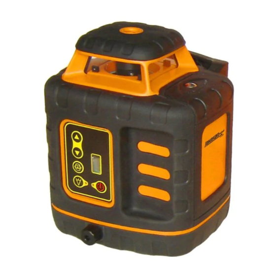
Self-Leveling Rotary Laser Level
Model No. 40-6527 & 40-6532
Instruction Manual
Congratulations on your choice of this Self-Leveling Rotary Laser Level.
We suggest you read this instruction manual thoroughly before using the
instrument. Save this instruction manual for future use.
This tool emits one rotating laser beam plus one plumb beam and is
ideal for laying out indoor and outdoor construction projects.
This is a Class IIIa laser tool and is manufactured to comply with CRF 21,
parts 1040.10 and 1040.11 as well as international safety rule IEC 285.
©2009 Johnson Level & Tool
1
Advertisement
Table of Contents

Subscribe to Our Youtube Channel
Related Manuals for AccuLine 40-6527


Summary of Contents for AccuLine 40-6527
- Page 1 10:09 AM Page 1 ® Self-Leveling Rotary Laser Level Model No. 40-6527 & 40-6532 Instruction Manual Congratulations on your choice of this Self-Leveling Rotary Laser Level. We suggest you read this instruction manual thoroughly before using the instrument. Save this instruction manual for future use.
-
Page 2: Table Of Contents
5. Location of Parts/Components 13. Product Registration 6. Operating Instructions 14. Accessories 7. Using the Product 1. Kit Contents Description for Model 40-6527 Qty. Self-Leveling Rotary Laser Tinted Glasses Alkaline Battery Compartment “C” Alkaline Batteries Instruction Manual with Warranty Card... -
Page 3: Features And Functions
2294H 4/9/09 10:09 AM Page 3 2. Features and Functions • Self leveling in the horizontal plane • Locking mechanism protects inner pendulum during transportation • Manual leveling in the vertical plane with 90º split beam • Range-scan modes include dot and two adjustable line lengths •... -
Page 4: Location/Content
• Do not attempt to repair or disassemble the laser tool. If unqualified persons attempt to repair this tool, warranty will be void. • Use only original AccuLine Pro ® parts and accessories purchased from your AccuLine Pro ® authorized dealer. Use of non-AccuLine Pro ®... -
Page 5: Location Of Parts/Components
2294H 4/9/09 10:09 AM Page 5 5. Location of Part/Components Battery-case locking screw Laser output window Remote control Battery case Receivers Keypad Vertical adjustment knob Calibration Handle and screw plug vertical bracket Transportation locking knob 5/8” thread holes ©2009 Johnson Level & Tool ©2009 Johnson Level &... -
Page 6: Operating Instructions
2294H 4/9/09 10:09 AM Page 6 6. Operating Instructions IMPORTANT: It is the responsibility of the user to verify the calibration of the instrument before each use. Battery Installation Note: Always check to be sure that the on/off switch is in the off position before removing and replacing batteries. -
Page 7: Using The Product
2294H 4/9/09 10:09 AM Page 7 7. Using the Product Operating Panel Rotation speed and scan keys HIgh rotation speed key Scan mode key Power Key Scanning LED Power LED 1. Power Key • Press this key to turn on and off the power 2. - Page 8 2294H 4/9/09 10:09 AM Page 8 5. High rotation speed key Press this key, the instrument will rotate in its highest speed 6. Rotation speed and scan keys In rotation mode • Press the up arrow to increase rotation speed •...
- Page 9 2294H 4/9/09 10:09 AM Page 9 2. Place the instrument on a platform or tripod, connect to the tripod using the 5/8" thread at the bottom of laser. Note: If instrument is inclined beyond its self-leveling range, it will deliver an audible alarm. Re-position the instrument until level. 3.
- Page 10 2294H 4/9/09 10:09 AM Page 10 Usage for vertical application IMPORTANT: Keep the transportation “Locking Knob” in the “Locked/Off” position. 1. Install batteries/battery pack (40-6532 only) as previously discussed. 2. Set the laser down on its vertical bracket. 3. Turn on the power by pressing the Power Key. The vertical vial will now be backlit.
- Page 11 2294H 4/9/09 10:09 AM Page 11 Detector Usage (included in Model No. 40-6532) 1. Technical Specifications Detecting accuracy Fine: ±0.039" (±1mm) Coarse 1: ±0.098" (±2.5mm) when range ≥ 492 ft. (150m) Coarse 2: ±0.394" (±10mm) when range ≥ 492 ft. (150m) Automatic Shut-off 6 min ±1min Power Supply...
- Page 12 2294H 4/9/09 10:09 AM Page 12 (b) Display 1. Power on symbol 2. Low battery indicator 3. Fine/Coarse symbol 4. Beeper symbol 5. Position indication arrows Power Key: Turn on/off the power Fine/Coarse Accuracy Key: Switch detecting accuracy LED Key: Turn on/off the LCD’s light Volume Key: Cycles between high, low and off 3.
- Page 13 2294H 4/9/09 10:09 AM Page 13 4. Operating Instructions Power On Press the power key to turn the unit on. The LCD display will illuminate all the indicator segments for 0.5 second (Fig.2). When the indicator segments are no longer illuminated, the detector is ready for use.
- Page 14 2294H 4/9/09 10:09 AM Page 14 Detecting Laser Level Signals While detecting laser signals, the LCD will display as follows: (take the set-up state of high sound and fine detection as an example) Laser signal Laser signal Laser signal The laser signal is down The laser signal is up Horizontal bar indicated on-grade No laser signal is detected...
- Page 15 2294H 4/9/09 10:09 AM Page 15 3. Keep the reception window facing the laser while detecting. 4. Hold the unit stable while detecting. LED Function Power on and press the LED key, the LCD will now be backlit. Automatic Shut-off Function When the unit does not receive a laser signal for 6 minutes, the unit will power off automatically.
- Page 16 2294H 4/9/09 10:09 AM Page 16 8. Self-Check and Calibration IMPORTANT: It is the responsibility of the user to verify the calibration of the instrument before each use. 30’ X-Direction Accuracy Self-Check 1. Place the unit on a platform that is 30 feet away from a wall, with the battery case facing towards the wall.
- Page 17 2294H 4/9/09 10:09 AM Page 17 X-Direction Accuracy Calibration 1. Turn the lock knob to the “OFF’ position. 2. Remove the rubber plug from the X-direction self-calibration aperture inside the battery compartment. Adjust the weight screw inside the instrument core with a flathead screwdriver.
-
Page 18: Accuracy Self-Check
2294H 4/9/09 10:09 AM Page 18 Y-Direction Accuracy Calibration 1. Turn the lock knob to the “OFF’ position. 2. Screw off the Y-direction self-calibration aperture bolt located behind the handle. Adjust the weight screw inside the instru- ment core with a flathead screwdriver. 3. -
Page 19: Technical Specifications
2294H 4/9/09 10:09 AM Page 19 6. Adjust the adjusting knob to make the laser beam aim at E. 7. Check the bubble to see if it is centered. If it is not yet - instrument will need to be sent in for calibration. 9. -
Page 20: Application Demonstrations
2294H 4/9/09 10:09 AM Page 20 10. Application Demonstrations Plumb reference for ceiling installation Reference for anti-static flooring installation Reference for window installation Reference for flooring Reference for squaring and leveling Reference for cement floor installation ©2009 Johnson Level & Tool... -
Page 21: Care And Handling
Do not return this product to the store/retailer or place of purchase. Required repair/calibration must be done by an authorized AccuLine Pro™ service center or Johnson Level & Tool's limited warranty, if applicable, will be void and there will be NO WARRANTY. -
Page 22: Product Registration
14. Accessories AccuLine Pro® accessories are available for purchase through authorized AccuLine Pro dealers. Use of non-AccuLine Pro accessories will void any applicable limited warranty and there will be NO WARRANTY. If you need any assistance in locating any accessories, please contact our Customer Service Department. -
Page 23: Johnson Level & Tool
2294H 4/9/09 10:09 AM Page 23 ©2009 Johnson Level & Tool... - Page 24 2294H 4/9/09 10:09 AM Page 24 ©2009 Johnson Level & Tool...
Need help?
Do you have a question about the 40-6527 and is the answer not in the manual?
Questions and answers