Table of Contents
Advertisement
Quick Links
Advertisement
Table of Contents

Summary of Contents for R-Tech I-MIG200
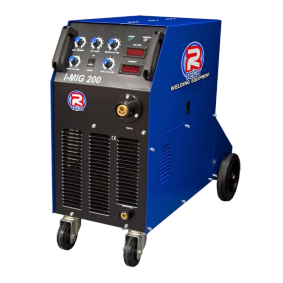
- Page 1 I-MIG200 MIG/MMA WELDER OPERATION INSTRUCTIONS...
- Page 3 Ideal for automotive work with its minimum current of 30 Amps. We want you to take pride in operating our I-MIG200 as much pride as we have taken in making this product for you. Please read all information in this manual before operation PLEASE EXAMINE THE CARTON AND EQUIPMENT FOR DAMAGE IMMEDIATELY When this equipment is shipped, title passes to the purchaser upon receipt from the courier.
-
Page 4: Technical Specifications
Welding Capability – Duty Cycle The R-Tech I-MIG 200 is rated at 200 Amps at 35% duty cycle on a ten minute basis. If the duty cycle is exceeded a thermal protector will shut machine off until the machine cools. - Page 5 Safety Precautions Read entire section before starting installation WARNING! Electric Shock can kill – Only qualified personnel should perform this installation. Turn off input power at the fuse box before working on this equipment. Do not touch electrically live parts. Always connect the machine to an earthed mains supply as per national recommended standards.
-
Page 6: Electrical Installation
Electrical Installation WARNING! ELECTRIC SHOCK CAN KILL Machine grounding and High Frequency Interference Protection This welder must be grounded to earth. See national electrical codes fro proper grounding methods. The high frequency generator being similar to a radio transmitter may cause interference to radio, TV and other electronic equipment. - Page 7 Turn the input power OFF at the mains switch & fuse box before working on this equipment. Have a qualified electrician install & service this equipment. Allow machine to sit for 5 minutes minimum to allow the power capacitors to discharge before working inside this equipment.
- Page 8 Connections for I-Mig 200 Rear machine connections Fig 1 1. Fuse Holder Fuse for wire feed motor protection 2. Auxiliary AC output For water cooler – Maximum load 3A – Do not connect to power tools etc 3. Gas inlet connection Connect gas hose to rear of machine and then to regulator on gas bottle.
- Page 9 Front machine connections Fig 2 1. Euro torch connector Connect Euro type Mig torch to euro torch connector, align torch connector to machine connector and then turn retaining ring clockwise to secure. Ensure torch is secured tightly to avoid weld power problems To avoid electric shock keep the Mig torch in good condition and replace if any of the insulation is damaged.
-
Page 10: Controls And Settings
Controls and Settings Fig3 1. Spot Welding This adjusts the amount of time the weld will last. When you press the torch switch the machine will do a single spot weld according to the time you have set and then stop, then release torch switch. - Page 11 5. On/Off Power Switch This turns the I-Mig200 Mig Welder on and off. 6. Wire Speed This adjusts the wire feed speed from 0-100% Adjust the wire speed to suit welding voltage (Fig 3.1) and job requirements When adjusting the wire feed speed a value is shown in the amperage LED (Fig 3.8)
- Page 12 Wire Spool Adjustment Fig 4 1. Wire reel retainer This screws onto wire reel holder to secure wire reel roll 2. Wire reel tensioner nut This adjusts the tension on wire feed reel which stops the reel from over running and causing wire to come of reel (birds nest) when torch switch is released.
- Page 13 2. Burnback control knob This sets amount of time welding power stays on after torch button released and wire feed has stopped. If too little Burnback is set, wire may stick to work after trigger released, if too much Burnback is set wire will Burnback into welding tip. 3.
-
Page 14: Operating Machine
Operating machine SAFETY PRECAUTIONS WARNING! ELECTRIC SHOCK CAN KILL Do not touch electrically live parts or electrode with skin or wet clothing. Insulate yourself from work and ground Always wear dry insulating gloves WARNING! FUMES AND GASES can be dangerous Keep your head out of fumes &... - Page 15 Next you will need to fit U-Groove rollers made specifically for alloy wire to the feed unit. These are available from R-Tech. Remove the steel rollers (V-Groove) from the machine and fit U-Groove rollers ensuring correct size groove is in line with the welding wire guides.
-
Page 16: Routine And Periodic Maintenance
5. The fan motor has sealed bearings which requires no maintenance Troubleshooting Service & repair should only be performed by R-Tech welding trained personnel. Unauthorised repairs performed on this equipment may result in danger or injury to the technician and machine operator and will invalidate your warranty. -
Page 17: Output Problems
No output – Power light is lit – Gas at torch tip – No wire feed Check wire feed unit protecting fuse on rear of machine, if blown replace with new fuse of same rating, If fuse flows again contact R-Tech •... -
Page 18: Wiring Diagram
Wiring Diagram...


Need help?
Do you have a question about the I-MIG200 and is the answer not in the manual?
Questions and answers