
Related Manuals for R-Tech INV160


Summary of Contents for R-Tech INV160
- Page 1 Tel: 01452 733933 Fax 01452 733939 INV160 PORTABLE INVERTER MIG WELDER OPERATION INSTRUCTIONS...
- Page 3 We want you to take pride in operating our INV160, as much pride as we have taken in making this product for you. Please read all information in this manual before operation PLEASE EXAMINE CARTON AND EQUIPMENT FOR DAMAGE IMMEDIATELY When this equipment is shipped, title passes to the purchaser upon receipt from the courier.
-
Page 4: Technical Specifications
Welding Capability – Duty Cycle The R-Tech INV160 is rated at 160 Amps at 30% and 115 Amps @ 60% duty cycle on a ten minute basis. If the duty cycle is exceeded a thermal protector will shut machine off until the machine cools. - Page 5 Amperage range 0.8mm wire 50-160 AMPS Suitable Wire Diameter 0.6mm 0.8mm Gross Weight 18 KG Insulation Class F Safety Precautions Read entire section before starting installation WARNING! Electric Shock can kill – Only qualified personnel should perform this installation. Turn off input power at the fuse box before working on this equipment.
-
Page 6: Electrical Installation
Read and follow the ‘Electric Shock Warnings’ in the safety section if welding must be performed under electrically hazardous conditions such as welding in wet areas or water on the work piece. Electrical Installation WARNING! ELECTRIC SHOCK CAN KILL Machine grounding and High Frequency Interference Protection This welder must be grounded to earth. - Page 7 Allow machine to sit for 5 minutes minimum to allow the power capacitors to discharge before working inside this equipment. Do not touch electrically live parts The INV160 Mig Welder requires a 240V 50/60Hz 1-Phase supply. It requires a 13A supply. It comes with a 3 metre mains cable attached.
- Page 8 Connect gas hose to rear of machine and then to regulator on gas bottle. Ensure all connections are tight to ensure no loss of gas. Make sure gas bottle is secured to machine securely using supplied chain to avoid injury. 5. On/Off Power Switch This turns the INV160 Mig Welder on and off.
-
Page 9: Controls And Settings
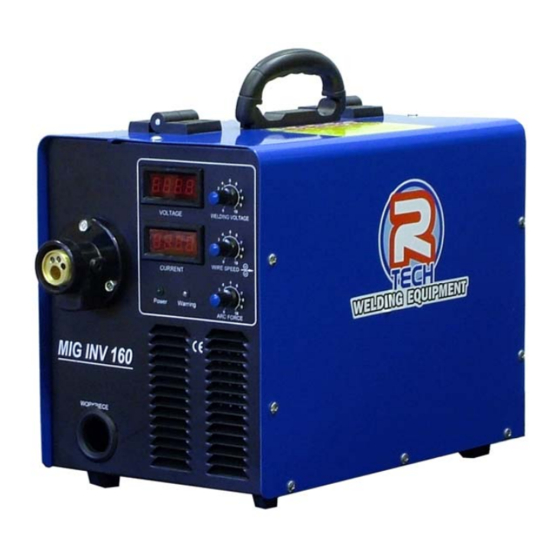
Controls and Settings Fig 3 1. Welding Voltage This adjusts the welding voltage (weld power) from 0 to 10. Adjust knob for power output required by job, preset welding voltage is shown in LED (Fig3.4) 2. Wire Speed This adjusts the wire feed speed from 0-100% Adjust the wire speed to suit welding voltage (Fig3.1) and job requirements When adjusting the wire feed speed a value is shown in the amperage LED (Fig3.5) This feature allows you to record this value along with the preset welding voltage for... - Page 10 This allows the machine to be calibrated to BS if required by your company 5. Amperage LED Display This shows the preset wire feed speed when no welding is being carried out When welding this shows the actual welding amperage This allows the machine to be calibrated to BS if required by your company 6.
- Page 11 The INV160 comes fitted with a dual roller 0.6mm and 0.8mm 4. Wire reel adaptor Remove the wire reel retainer and wire reel adaptor, slide on roll of wire and refit the reel adaptor (This can be reversed to suit different manufacturer’s reel sizes)
-
Page 12: Operating Machine
Operating Machine SAFETY PRECAUTIONS WARNING! ELECTRIC SHOCK CAN KILL Do not touch electrically live parts or electrode with skin or wet clothing. Insulate yourself from work and ground Always wear dry insulating gloves WARNING! FUMES AND GASES can be dangerous Keep your head out of fumes &... - Page 13 The INV160 is fitted with rollers suitable for both steel and alloy wire as standard Fit oversize welding tip. These are available and have and ‘A’ after tip size. I.E 0.8A where as for steel wire it would just say 0.8...
-
Page 14: Routine And Periodic Maintenance
5. The fan motor has sealed bearings which requires no maintenance Troubleshooting Service & repair should only be performed by R-Tech welding trained personnel. Unauthorised repairs performed on this equipment may result in danger or injury to the technician and machine operator and will invalidate your warranty. -
Page 15: Output Problems
R-Tech by phone. Contact details can be found on our website Output Problems • No output - Power light is not lit Check machine on/off switch is in the ‘on’ position Check Input power to machine Check plug wiring Check mains trip / fuses •... -
Page 16: Wiring Diagram
Wiring Diagram...
Need help?
Do you have a question about the INV160 and is the answer not in the manual?
Questions and answers