Table of Contents

Subscribe to Our Youtube Channel
Related Manuals for JRC FF50


Summary of Contents for JRC FF50
- Page 1 INSTRUCTION MANUAL COLOR FISH FINDER COLOR FISH FINDER...
-
Page 3: Before You Begin
COLOR Fish Finder FF50 Before You Begin Thank you for purchasing our JRC color LCD Fish Finder FF50. This unit displays fish schools in color on a bright TFT LCD screen. • This unit is for detecting schools of fish. Before attempting to... -
Page 4: Symbols Used In This Manual
Symbols Used In This Manual Related Symbol Marks In this manual, and on the equipment, we use several warning signs to call your attention to important items that, if not handled correctly, could present danger to yourself or property. These warning note classifications are as described below. -
Page 5: Usage Hints
Usage Hints WARNING Operate the unit only Do not remove the cover of the on 12 VDC to 24 VDC. unit. Doing so may cause an Not doing so may electric shock cause fire or by high voltage electrical shock. from within the product’s enclosure. - Page 6 CAUTION Do not try to turn When disconnecting on the main unit while the power cable, the transducer is be sure to grasp disconnected or it by the plug. Never pull on the out of the water. connecting cord Doing so may cause itself, as doing so an electrical shock increases the risk...
-
Page 7: Emc Installation & Service Guidelines
In general this will not damage the equipment but it can lead to it resetting, or momentarily may result in faulty operation. This can then be avoided by turning off the FF50 prior to starting the boat engines for instance. -
Page 8: Servicing And Safety
• Some products generate high voltages, and so never handle the cables /connec- tors when power is being supplied to the equipment. • Always report any EMC related problem to your nearest JRC dealer. We will use any such information to improve our quality standards. -
Page 9: Outside View
Outside View FF50 Display Unit Transducer Either one of transducers shown below can be used. CFT-2501TFA CFT-2501HFA... -
Page 10: Table Of Contents
Contents Before You Begin ................1 Symbols Used In This Manual ............2 Usage Hints ..................3 EMC Installation & Service Guidelines ........... 5 Outside View ..................7 Definition on Terms................. 13 SECTION 1 Introduction ........15 Function ..................15 Features ..................16 Components ..................17 Standard Equipment.............. - Page 11 Using a Thru-Hull Transducer ............35 Before You Install ................. 35 Selecting the Best Location ............35 Using a Fairing Block ..............36 Installing the Thru-Hull Transducer ..........37 Connecting DC Power ..............38 Grounding the Display Unit ............39 Connecting GPS/DGPS Sensor or Making NMEA0183 Data Connections (Option) ...............40 Connecting GPS100 or DGPS200 sensor ....
- Page 12 Frequency Changing..............51 Display Mode Selection ..............51 STD Single Frequency Mode ..........51 STD Dual Frequency Mode ............ 52 STD Single Frequency with A-Scope Mode ......52 STD Dual Frequency with A-Scope Mode ......52 STD Single Frequency with VRM Zoom Mode ...... 53 STD Single Frequency with Auto Zoom Mode .......
- Page 13 Selecting Sequence Mode for Following Route ......70 Setting CDI Range..............70 Monitor Mode ................ 70 Installation Menu ................. 71 Simulator ................71 Selecting Temperature Input ........... 71 Selecting Speed Input .............. 72 Selecting Position Input ............72 Power Down Control .............. 73 EXP Range Mode Setting............
- Page 14 GPS/DGPS Basics .................91 GPS ....................91 Differential GPS (DGPS) ............. 92 SECTION 7 After-Sales Service ....... 93 When asking for service ..............93 Checks and inspection ..............93 SECTION 8 Disposal ..........94 Disposal of LCD Module ............. 94 Disposal of Fish finder ..............94 Handling Used Lithium Batteries ..........
-
Page 15: Definition On Terms
Definition on Terms 2D (two-dimentional) ..Position fixing using satellites and height information. 3D (three-dimensional) ... Position fixing using satellite information only from four or more satellites Anchor alarm ....An alarm indicating that the vessel has deviated more than the set distance from a waypoint. Arrival alarm .... - Page 16 Initialization ....It takes up to 20 minutes for GPS position fixing when it is used for the first time or after a master reset has been performed. This time can be reduced by entering initialization values such as estimated posi- tion, time and antenna height.
-
Page 17: Section 1 Introduction
SECTION 1 Function The Color Fish Finder FF50 is a system that uses the basic principles of sonar to show lake or seabed conditions and to detect fish. It consists of a transducer, which is installed on the transom, or thru-hull transducer, and a display unit. -
Page 18: Features
Features DUAL FREQUENCY Because two frequencies, 200 kHz and 50 kHz can be used, the areas used to search for schools of fish is more flexible and information on the type of fish or seabed can be better determined by comparing echoes of each frequency. The display in the dual-frequency mixed mode is also available. -
Page 19: Components
Components When unpacking your FF50, you should find the following standard equip- ment in the carton. If any items are missing, please notify your JRC dealer imme- diately. Standard Equipment No Description Model No. Qty. Remarks Fish Finder JFC-500 Transducer... -
Page 20: Construction
Construction 3.3" (84 mm) 0.5" (12 mm) 1.1" (27 mm) 2" (50 mm) 9" (228 mm) 7.4" (187 mm) 5.9" (150 mm) 4- 0.3" (187 mm) Unit : inch (mm) Figure 1-2... -
Page 21: System Configuration
System Configuration GPS (DGPS) SENSOR NMEA0183 INPUT/OUTPUT POWER 12/24 VDC (11-32VDC) TRANSDUCER CFT-2501TFA 200/50 kHz TRANSOM CFT-2501HFA 200/50 kHz Through-hull Figure 1-3... -
Page 22: Panel
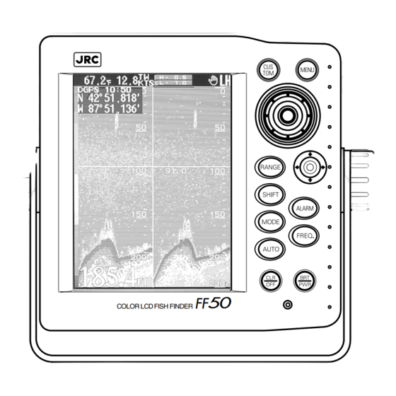
Screen Layout, SECTION 2 Control Panel and Rear Panel Screen Layout WARNING The digital depth reading accuracy can be affected by many factors including improper installation, equipment failure, environmental conditions, and improper use. It is the user’s responsibility to exercise common prudence and good naviga- tional judgment. - Page 23 No. ITEMS Displaying symbols q WATER Two scales, Fahrenheit ( F) and Celsius ( C), are selectable. TEMPERATURE* w AUDIO ALARM : Buzzer is set to sound. Note : Not displayed when BuzzerOFF is selected. BUZZER MARK e SHIP POSITION Ship position is available when used with GPS SENSOR or NMEA 0183 format DATA* data is received.
-
Page 24: Control Panel
Control Panel Figure 2-2 shows the panel keys and their functions. Figure 2-2 Control Panel No. Keys Functions !2 CUSTOM Restore display to user customized set-up. !3 MENU Push to display the menu. !4 JOG-DIAL Push and turn: Adjusts GAIN LEVEL. Turn: Moves VRM up or down. -
Page 25: Rear Panel
No. Keys Functions !8 ALARM Sets each Alarm to ON/OFF and its conditions to activate it. !9 MODE Set display modes with the joy-stick. @0 FREQ Switches frequencies in the Single-Frequency mode. @1 AUTO Executes or cancels each AUTO mode. Executes GOTO (direct route setting) in the NAVIGATION mode. -
Page 26: Section 3 Installation
Leaving the equipment in this condition may cause electric shock or malfunction. The two most important considerations for mounting the FF50 Color Fish Finder display unit are: • Choosing the best location for operating and viewing •... - Page 27 To mount the unit, remove the mounting yoke from the unit by loosening the yoke knobs on each side of the FF50. Attach the bracket to the desired mounting surface with the setting screws (o6x25SUS, 4Qty.) included in the kit, refering to Figure 1-2.
-
Page 28: Console Mounting/ Surface Mounting
Console Mounting/ Surface Mounting CAUTION Make sure there no hidden electrical wires or other items behind the desired location before proceeding. Also check that you have free access for mounting and cabling. 1) Select a mounting location: a clear, flat area of at least 8"(203mm) wide by 8" high, having 5.5"(140mm) depth behind the panel. -
Page 29: Installing The Transducer
(hard, soft etc.) of the seabed. The transducer is the heart of the FF50 operation. It is a delicate instrument and should be handled carefully. The position that you mount the transducer is extremely important and this directly affects the performance and operating efficiency of the unit. - Page 30 Height without speed sensor 7-1/2" (191mm) height Height with speed sensor 8-1/2" (213mm) Height required at mounting location Figure 3-4 CAUTION Do not mount the sensor in an area of turbulence or bubbles: Near water intake or discharge openings; Behind strakes, struts, fittings, or hull irregularities; Behind eroding paint (an indication of turbulence).
-
Page 31: Attaching The Transducer To The Transom
Attaching the Transducer to the Transom Align template vertically P66 Installation template for starboard side of boat deadrise angle slope of hull Drill at locations labeled “B” parallel to waterline for the following transom angles: 16˚ through 22˚ Align template arrow with bottom edge of transom Template position Figure 3-6... - Page 32 2 –10 transom angle 11 transom angle 19 –22 transom angle NO SHIM shim with shim with taper down taper down parallel parallel parallel 12–18 transom angle NO SHIM angle angle slight reversed too steep angle Sensor angle adjustment on transom Figure 3-7 Adjusting ➀...
- Page 33 CAUTION Do not position the sensor farther into the water than necessary to avoid increasing drag, spray, and water noise and reducing boat speed. ➄ Using the vertical adjustment space on the bracket slots, slide the sensor up or down to provide a projection of 1/8" (3mm). Tighten the screws (see Figure 3-9).
-
Page 34: Cable Routing
Cable Routing Route the sensor cable over the transom, through a drain hole, or through a new hole drilled in the transom adove the waterline. CAUTION Never cut the cable or remove the connector; this will void the warranty. WARNING Always wear safety goggles and a dust mask. -
Page 35: Testing On The Water
cable cover cable clamp 2"(50mm ) Hull projection 1/8" (3mm) Vertical adjustment and cable routing Figure 3-9 Testing on the Water ➀ Become familiar with your echosounder’s performance at a speed of 4kn (5MPH). ➁ Gradually increase the boat speed and observe the gradual decline in performance due to turbulent water flowing over the transducer’s active surface. -
Page 36: Maintenance
Maintenance Cleaning Clean the sensor with a soft cloth and mild household detergent. If fouling occurs, use a stiff brush or putty knife to remove the growth being careful to avoid making scratches on the transducer’s face. In severe cases, wet sand the surface with fine grade wet/dry paper. -
Page 37: Using A Thru-Hull Transducer
➔ Follow appropriate procedures for thru-hull mounting in core hull structures. If you are in any doubt about installation, consult your boat representative, or JRC dealer. Selecting the Best Location If properly installed the thru-hull transducer will be: •... -
Page 38: Using A Fairing Block
Figure 3-12 shows best location for the thru-hull transducer. Best locations vary with the type of vessel. On any vessel, try to find a spot with the smallest deadrise angle. Sailboats Tri-hulls Best locations for thru-hull transducers Planing hulls Figure 3-12 Using a Fairing Block If necessary, use a fairing block as shown in Figure 3-13 to keep the transducer perpendicular to the waterline, especially if the deadrise angle at the... -
Page 39: Installing The Thru-Hull Transducer
Installing the Thru-Hull Transducer You may wish to drill a 1/8" (3.2 mm) pilot hole from the inside to assure access to the housing nut and clearance for the cable. Drill from the outside if there is a strake or other hull irregularity. Use caution when sanding or cleaning as harsh cleaning solvents such as acetone weaken some epoxy resins and may damage the transducer. -
Page 40: Connecting Dc Power
Connecting DC Power WARNING Do not touch the ground terminal and vessel ground on the display unit at the same time without the ground terminal earthed. Otherwise, you may suffer an electric shock. CAUTION RED to the positive. BLACK to the negative. Do not mistake the colors, as doing so will cause a malfunction. -
Page 41: Grounding The Display Unit
Connector to The unit is internally protected NMEA 0183 from accidental reverse polarity. Input/Output Reversing the power leads will not damage the unit, it will Connector to simply not turn on. GPS/DGPS Sensor connector to transducer 12/24 VDC (11-32 VDC) connector to battery 3 amp fuse... -
Page 42: Connecting Gps/Dgps Sensor Or Making Nmea0183 Data Connections (Option)
When displaying the latitude and longitude of your vessel on the screen, or using the NAVIGATION mode, you are required to connect the optional GPS100 or DGPS200 sensor to the FF50, or input the data of navigational information in the NMEA0183 format from navigation equipment. - Page 43 (2) locking posts on the connector body. This is a tight connection. For leverage it may be helpful to first insert and lock the connector into its mating plug on the FF50 back panel. GROMMET...
-
Page 44: Section 4 Operation
Operation SECTION 4 Basic Operations The Power Control • Push once to turn the power on. • Push simultaneously to turn the power OFF. LCD Backlight and Contrast Control • Push to display the Bright/Cont Control menu. Press the up or down to select brightness or contrast. The selected item is highlighted. -
Page 45: Range Setting
If you make no key operation for 7 seconds, the menu closes automatically. Automatic Mode Selection • The FF50 provides four automatic operation modes relating to the fish finding functions. These four modes are SEARCH, CRUISE, AUTO RANGE and AUTO SHIFT. -
Page 46: Search Mode
Search Mode • In this mode, the range scale and gain level are controlled automatically, optimized for Fish finding. Select this mode when you navigate while looking for schools of fish. • Push to display the AUTO MODE menu. Press the up or down to select SEARCH and push it in to enter the SEARCH mode. -
Page 47: Auto Range
Auto Range • In this mode, the range scale is controlled automatically so that the sea bottom is always displayed on the screen. Select this mode when you are looking for schools of fish in a large area from the sea surface to the sea bottom. -
Page 48: Alarm Settings
Alarm Settings • The FF50 provides three fish finding alarms, three water temperature alarms, four navigation alarms and a function to turn the alarm buzzer on or off. Use appropriate alarms for safer navigation and more efficient fish finding. The functions and operations are described below. -
Page 49: Deep Alarm
• Push to display the ALARM menu. Press the up or down to select SHALLOW and push it in to display the SHALLOW ALARM ON/OFF and depth value setting pull-down menu. Specify a depth value, select ON and push the in to turn the SHALLOW ALARM on. -
Page 50: Temperature Lower Limit Alarm
Temperature Lower Limit Alarm • When turned on, this alarm shows a message on the screen and also sounds the buzzer when the temperature value sensed is at or less than the operator’s preset lower temperature value. • Push to display the Alarm menu. Press the up or down to select TEMP LOWER and push it to display the TEMP LOWER ALARM ON/OFF and Temperature... -
Page 51: Anchor Alarm
• Push to display the ALARM menu. Press the up or down to select ARRIVAL and push it in to display the ARRIVAL ALARM ON/OFF and distance setting pull- down menu. Specify a distance, select ON and push the in to turn the ARRIVAL ALARM on. -
Page 52: Off Course Alarm
Off Course Alarm • When turned on, this alarm shows a message on the screen and also sounds the buzzer when the deviation from the intended course becomes equal to or greater than the operator’s preset value. • Push to display the ALARM menu. Press the up or down to select OFF COURSE and push it in to open the OFF COURSE ALARM ON/OFF and distance... -
Page 53: Alarm Buzzer
The FF50 provides 11 display modes. You can obtain the optimum display according to various purposes such as game fishing or normal navigation. The displays of each mode are described below. -
Page 54: Std Dual Frequency Mode
STD Dual Frequency Mode • Select STD DUAL to divide the screen vertically in two in the ratio of 1:1. It shows the high frequency standard display on the right side of the screen and the low frequency standard display on the left side of the screen. -
Page 55: Std Single Frequency With Vrm Zoom Mode
STD Single Frequency with VRM Zoom Mode • Select STD/ZOOM to divide the screen vertically in two in the ratio of 1:1. It shows the high or low frequency standard display on the right side of the screen and the magnified display of the area specified in the ZOOM RANGE setting, with VRM being in the center of the standard display on the left side of the screen. -
Page 56: Std Single Frequency With Bottom Discrimination Mode
Therefore, the echoes displayed in the normal color on the high frequency preferred mixed display may be regarded as small fish. On the other hand, the beam of the Transducer connected to the FF50 is narrow in the high frequency and wide in the low frequency. Echoes... -
Page 57: Navigation Mode Type1 (Graphic Display)
Navigation Mode type1 (Graphic Display) • Select STD/NAV1 to divide the screen vertically in two in the ratio of 6:1. It shows the high or low frequency standard display on the right side of the screen and the NAVIGATION type1 window on the left side of the screen. -
Page 58: Navigation Mode Displays Data
Refer to Section 3-5 for information about connection. After connection, be sure to check that the NMEA0183 sentences of $xxHDG, $xxHDT or $xxHDM are output. (You can check this easily using the selftest mode of the FF50.) -
Page 59: Navigation Mode Operations
Navigation Mode Operations • The Trip Log modes (STD/NAV1, STD/NAV2) provide GOTO, EVENT and WAYPOINT skip functions to facilitate navigation when you navigate to stored waypoints or you navigate from a route plan list. You can use these functions with soft keys dedicated to this mode. -
Page 60: Follow The Route Plan
Follow the Route Plan • You can use this function when you activate the NAVIGATION mode according to the navigation plan stored previously. • Push to open the NAVIGATION menu. Select FOLLOW ROUTE and push the in to open the pull-down menu in which you select a route and trace direction. -
Page 61: Menu Opening
Menu Opening • Push to display the Top menu. Push in the NAVIGATION mode to skip the Top menu and display the NAVIGATION menu. To close all menus, push while any menu is open. • Refer to “Menu operations” p.60 for details about menu operations. Storing and Resetting Custom Data •... -
Page 62: Menu Operations
Menu Operations General • There are three types of menus, Top menu, Navigation menu and Installation menu. Following the basic operations described below, you can easily perform all menu operations using only the Selecting an item: Press the up or down to select an item and push it in to complete the selection. - Page 63 Push the Push the...
- Page 64 Push the Push the Push the Push the Push the Push the Push the...
-
Page 65: Top Menu
Top Menu • This menu includes frequently used fish finding settings. You can go to the NAVIGATION menu or INSTALLATION via this Top menu. Chart Speed Setting • You can set the chart speed of fish echoes using this item. •... -
Page 66: Interference Rejection Setting
Interference Rejection Setting • You can set the level to reduce interference from other vessels using this item. The interference is the noise that is caused when waves transmitted from the ultrasonic equipment such as a fish finder on a nearby vessel are reflected from the seabed toward your vessel. -
Page 67: Color Sample Bar Display
Color Sample Bar Display • You can set this item to show the color sample bar. • Press the up or down to select SAMPLE BAR and push it in to open the color SAMPLE BAR setting pull-down menu. Press the to the left or right to select ON or OFF. -
Page 68: Edit Waypoint
Edit Waypoint • You can store, modify, copy and delete waypoints using this item. • Press the up or down to select EDIT WPT and push it in to open the WAYPOINT list. You can store up to 400 waypoints. The list is composed of 40 pages, each page consists of 10 waypoints. - Page 69 Copying waypoints Select a waypoint number you want to copy and push the to open the menu to select MODIFY, COPY or DELETE. Press the up or down to select COPY and push it in to open the COPY destination setting pull-down menu. Then, press the up or down to select a waypoint number as the destination.
-
Page 70: Editing Route Plans
ROUTE PLAN list of the selected ROUTE number. • Up to five route plans can be stored in the FF50, and each route plan can hold up to 40 waypoints in the order of the waypoints traversed. -
Page 71: Starting Follow The Route
Changing waypoints Select the waypoint number you want to change and push the in to display the menu to select CHANGE, INSERT or DELETE. Press the up or down to select CHANGE and push it in to display the WAYPOINT list. Then, select the waypoint number to replace and push the in to display the waypoint information and open the menu to select OK or CANCEL. -
Page 72: Selecting Sequence Mode For Following Route
In the monitor mode, navigation using the waypoints and route plans stored in the FF50 are not available. In addition, any functions dedicated to the navigation mode, namely, GOTO, EVENT registration, FOLLOW ROUTE, WAYPOINT skip are not available. -
Page 73: Installation Menu
FF50. While the simulator is activated, you can simulate almost all operations except the operation of the INSTALLATION Menu. -
Page 74: Selecting Speed Input
(You can check this easily using the self test mode of the FF50.) Selecting Speed Input • You can set the source of the vessel speed using this item. The FF50 can measure the vessel speed using the vessel speed sensor integrated into the Transducer or input NMEA0183 formatted vessel speed data from the GPS/DGPS sensor or the external navigation aids. -
Page 75: Power Down Control
NMEA0183 sentences of $xxGGA or $xxRMC are output from the connected external navigation aids. (You can check this easily using the selftest mode of the FF50.) Power Down Control • You can set the transmission power level of the high and low frequencies using this item. -
Page 76: Graph Scale Settings
Graph Scale Settings • You can set the scale of the water depth/temperature graph using this item. • Press the up or down to select GRAPH SCALE>> and push it in to switch to the GRAPH SCALE menu. 1. Depth Graph Scale Setting •... -
Page 77: Changing Temperature Units
3. Changing Temperature Units • You can set the temperature unit using this item. • Press the up or down to select TEMP UNIT and push it in to open the water temperature unit setting pull-down menu. Press the to the left or right to select Centigrade or Fahrenheit. 4. -
Page 78: Draft Offset
3. Draft Offset • Using this item, you can set the average draft (vertical distance between the Transducer surface and the sea surface) of your vessel. Usually the fish finder displays echoes from the area under the transducer surface. When you add the draft offset, the echoes are shifted lower by the amount of the draft offset and all echoes are with respect to the water line. -
Page 79: Gain Offset
LOG is the sum of the navigated distances (up to 999.9NM) and displayed at the top of the screen in the NAVIGATION mode. The value of the TRIP LOG is maintained after the FF50 is turned OFF. • Press the up or down to select RESET LOG and push it in to open the trip log reset pull-down menu. -
Page 80: Initialize Gps/Dgps Sensor
MANUAL. Initialize GPS/DGPS Sensor • Using this item, you can perform the initial settings when JRC’s GPS/ DGPS sensor GPS100 or DGPS200 is connected to the FF50. The menu includes both basic settings and initial settings. The basic settings reflect the general GPS/DGPS sensors and the initial settings reflect the beacon module of the DGPS sensor. - Page 81 (2) Date and Time (Local) • You can set the current date and time (local) using this item. • Press the up or down to select DATE/TIME and push it in to open the DATE/TIME setting pull-down menu. Press the up or down to set the current date and time while pressing to the left and right to move the setting frame.
- Page 82 (6) Fix Mode • You can set the geodetic mode of the GPS/DGPS sensor. • Press the up or down to select FIX MODE and push it in to open the FIX MODE setting pull-down menu. Press the the left or right to select 2D, 3D or AUTO. When the GPS100 is connected, 3D provides more precise data than 2D.
-
Page 83: Dgps Beacon Settings
(10) Transmit Command to GPS/DGPS Sensor • Using this item, you can send the set values in GPS/DGPS Basic Settings (1) - (9) to the GPS/DGPS sensor. • Press the up or down to select TX COMMAND and push it in to open the TRANSMIT COMMAND pull-down menu. - Page 84 (3) Baud Rate • You can set the baud rate used by the beacon using this item. • Press the up or down to select BAUDRATE and push it in to open the BAUD RATE setting pull-down menu. Press the to the left or right and select 50bps, 100bps or 200bps.
-
Page 85: Adjust The Bottom Judgement Level
Adjust the Bottom Judgement Level • If soft sludge has collected at the sea bottom, or it is the rock and the contour variation is extreme, the Digital Depth Reading might not coincide with the bottom echoes on the screen. In this case, adjust the Bottom Judgment Level in the following procedure. -
Page 86: Self Test Operation
Self test Operation • The FF50 has a built-in self test function with which you can check the operating status of the FF50 automatically. Moreover, a function of monitoring input NMEA0183 formatted sentences is attached to the self test function, and you can easily check various data input from external equipment. -
Page 87: Master Reset And Language Select Operation
Note: When a backup error occurs, the FF50 enters the MASTER Reset mode automatically, and the language select menu opens. In this case, you cannot abort the MASTER reset. Be sure not to turn the power... - Page 88 Item Master Reset Conditions Selected Language English, Italian Other Back Light Contrast Range Zoom Range Shift Gain HF=3.5, LF=3.5 Display Mode STD DUAL Auto Mode MANUAL Fish Alarm Shallow Alarm OFF, 32 OFF, 10 Deep Alarm OFF, 164 OFF, 50 Temp Upper Alarm OFF, 60.0 OFF, 15.6...
- Page 89 Calibration Calib.Temp Calib.Speed Draft Keel Height Gain Offset HF=0, LF=0 Reset Log Magnetic Corr. MANUAL 0.0 GPS Setting Position N 00 00.000' W000 00.000' Time Diffrence 00:00 Anntena Height Geodetic Datum WGS-84 Fix Mode AUTO HDOP level Average Exclude Satellite none DGPS Setting Beacon Receive Mode...
-
Page 90: Section 5 Maintenance
Maintenance SECTION 5 WARNING Do not try to service the interior of the unit, except by qualified service personnel, as doing so may cause an electric shock or functioning error. Call our company, branch, local office, or authorized agent for maintenance and inspection of this unit. Note Before you go any further, please take a few minutes to fill out the warranty card and send it in at your earliest... -
Page 91: Section 6 Principal
Echo Sounding As the boat travels, echoes returning to the transducer are received which continuously update the FF50 display. Receiving and identifying echoes from fish can depend on several factors including: •Species of fish •Number and size of fish... -
Page 92: Seabed Conditions
• When the seabed is made up of coral, wrecks, or rock piles, the irregular surfaces and various angles of the seabed return closely spaced echoes. The bottom line on your display appears with irregular long tails. Seabed Displays The FF50 high-resolution display provides accurate representations of various bottom conditions. Hard (Sand) -
Page 93: Gps/Dgps Basics
GPS/DGPS Basics The Navstar/GPS system is a satellite-based radio navigation system designed to provide global, continuous 24 hour-per-day, all weather, accurate position data for navigators. The GPS(Global Positioning System) is based on a GPS sensor’s ability to accurately measure the propagation time of signals transmitted from orbiting satellites in your sensor. -
Page 94: Differential Gps (Dgps)
Differential GPS (DGPS) The differential GPS comprises a reference station with its position(latitude and longitude) accurately known, a beacon station for radio broadcasting of DGPS correction data, and user-owned GPS sensor equipped with a differential correcting function. The GPS sensor is used to fix the position of the reference station whose position is accurately known and to eompare this with the actual reference station position to get range errors. -
Page 95: Section 7 After-Sales Service
For information on maintenance, contact your dealer. Note that maintenance is charged for. Inquiries should be directed to JRC. Addresses and telephone numbers are listed on the back cover of this manual. -
Page 96: Section 8 Disposal
Disposal SECTION 8 WARNING Before you dispose of a lithium battery, place a piece of adhesive tape across the plus an minus terminals to prevent electric shorts that could result in fire, explosions or other hazards. Disposal of LCD Module The fluorescent lamp built in the LCD module contains mercury. -
Page 97: Section 9 Specification
Specification SECTION 9 Display 6.5 inch Color LCD (TFT) Resolution 320 dots (Screen Size 133 mm 97 mm) Presentation 8 or 16 Color Gradation with 2 Patterns Brightness Control 10 steps Contrast Control 10 steps Range Auto or Manual: 5 to 1,500 m 10 to 5,000 ft 3 to 1,000 fm Shift... - Page 98 Simulator Built-In Audible-visual alarms Fish, Shallow, Deep, Temp Upper, Temp Lower, Temp Rate, Arrival, Anchor, Off cource, DGPS Waypoints Max. 400 points. Route plans 10 plans, 40 waypoints per route. Memory Backup Includes Battery Option NAVAID Input : GPS100/DGPS200 sensor NMEA0183 format Input Voltage 12 to 24 VDC...
-
Page 99: Appendices
APPENDICES Wiring Diagram 6.5 INCH COLOR LCD A901 H-7WSBS7001 (EDTCA14QCF) DATA CABLE CCFL CABLE W902 H-7ZCBS7017 J303 J501 J302 J702 DPU UNIT PANEL UNIT CML-595 CCK-829 J300 J301 W400 W401 TRX UNIT CMN-526 POWER CABLE H-7ZCBS7018 TRANSDUCER NMEA I/O GPS IN DC IN (CFQ-6382) J402... -
Page 100: Parts List
Parts List Item Part No. Main PCB CML-595 TRX PCB CMN-526 Panel PCB CCK-829 LCD Module 7WSBS7001 Power Cable CFQ-6382 (7ZCBS7018) Front Panel MTV302658 Filter MTT305899 Jogdial Knob MPHD30171 Joystick Cap MPPK30372 Contact Rubber (silicone rubber key) MTV302660 Gasket MTV302538 Yoke Bracket MTB344486 Yoke Knob... -
Page 101: Geodetic System Table
Geodetic System Table NAME WGS-84 WGS-72 Tokyo Bessel North American 1927 (America) North American 1927 (Canada, Alaska) European 1950 (Europe) Australian geodetic 1966 (Australia) Ordnance Survey of Great Britain (England) NAD-83 No Use No Use Adindan (Ethiopia and Sudan) ARC 1950 (Botswana) Australian Geodetic 1984 (Australia) Bermuda 1957 (Bermuda Islands) Bogota Observatory (Colombia) -
Page 102: Nmea0183 Standard Input/Output Sentences
NMEA0183 Standard input/output sentences Input sentences $xxAPA Heading/Track Controller (Autopilot) Sentence“A” $xxAPB Heading/Track Controller (Autopilot) Sentence“B” $xxBWC Bearing & Distance to Waypoint $xxBWR Bearing & Distance to Waypoint - Rhumb Line $xxGGA Global Positioning System Fix Data $xxHDG Heading, Deviation & Variation $xxHDT Heading - True $xxMTW... -
Page 103: Waypoint List
Waypoint List Waypoint no. Waypoint name Remarks... - Page 104 Waypoint no. Waypoint name Remarks...
- Page 105 Waypoint no. Waypoint name Remarks...
- Page 106 Waypoint no. Waypoint name Remarks...
-
Page 107: Offices Address List
OFFICES ADDRESS LIST...
Need help?
Do you have a question about the FF50 and is the answer not in the manual?
Questions and answers