Advertisement
Table of Contents
- 1 General Information
- 2 Before You Begin
- 3 Usage Hints
- 4 Table of Contents
- 5 Specifications
- 6 Component
- 7 Outline Drawing
- 8 Installing the Display Unit
- 9 Circuit Block Diagram
- 10 Parts Layout
- 11 Mechanical Parts List
- 12 Master Reset and Language Select
- 13 Self Test
- Download this manual
See also:
Instruction Manual
Advertisement
Table of Contents

Related Manuals for JRC FF50


Summary of Contents for JRC FF50
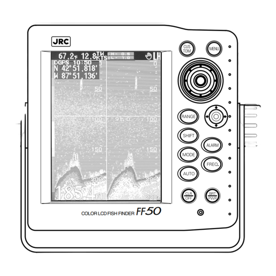
- Page 1 COLOR LCD FISH FINDER FF50 SERVICE MANUAL Document No. 7ZPBS4104...
-
Page 3: General Information
General Information This service manual describes the maintenance and inspection procedures for the FF50. Prior to the installation, users are requested to read this manual well and familiarize with its contents so that an optimum function may be derived from the FF50. -
Page 4: Before You Begin
Before You Begin Symbols Used In This Manual Related Symbols Marks In this manual, and on the equipment, we use several warning signs to call your attention to important to items that, if not handled correctly, could present danger to yourself or property. These warning note classifications are as described below. -
Page 5: Usage Hints
Usage Hints WARNING When installing this set, be sure to connect grounding wire grounding terminal of the set. Otherwise, an electric shock can result when a failure or leakage occurred on the set. Do not damage, break or modify the power cord. - Page 6 CAUTION When removing the power cord, be sure to remove the power cord terminal correctly. Pulling the power cord can damage it resulting in a fire or an electric shock. •@ Do not bring the set in a cooled state suddenly into a warm room.
-
Page 7: Table Of Contents
Index General Information ¥¥¥¥¥¥¥¥¥¥¥¥¥¥¥¥¥¥¥¥¥¥¥¥¥¥¥¥¥¥¥¥ ¥¥¥¥¥¥¥¥¥¥¥¥¥¥¥¥¥¥¥¥¥¥¥ Before You Begin ¥¥¥¥¥¥¥¥¥¥¥¥¥¥¥¥¥¥¥¥¥¥¥¥¥¥¥¥¥¥¥¥ ¥¥¥¥¥¥¥¥¥¥¥¥¥¥¥¥¥¥¥¥¥¥¥¥¥ Usage Hints¥¥¥¥¥¥¥¥¥¥¥¥¥¥¥¥¥¥¥¥¥¥¥¥¥¥¥¥¥¥¥¥ ¥¥¥¥¥¥¥¥¥¥¥¥¥¥¥¥¥¥¥¥¥¥¥¥¥¥¥¥¥¥ Index¥¥¥¥¥¥¥¥¥¥¥¥¥¥¥¥¥¥¥¥¥¥¥¥¥¥¥¥¥¥¥¥ ¥¥¥¥¥¥¥¥¥¥¥¥¥¥¥¥¥¥¥¥¥¥¥¥¥¥¥¥¥¥¥¥ ¥¥¥¥5 1. Specifications ¥¥¥¥¥¥¥¥¥¥¥¥¥¥¥¥¥¥¥¥¥¥¥¥¥¥¥¥¥¥¥¥ ¥¥¥¥¥¥¥¥¥¥¥¥¥¥¥¥¥¥¥¥¥¥¥¥¥¥¥¥ 2. Component ¥¥¥¥¥¥¥¥¥¥¥¥¥¥¥¥¥¥¥¥¥¥¥¥¥¥¥¥¥¥¥¥ ¥¥¥¥¥¥¥¥¥¥¥¥¥¥¥¥¥¥¥¥¥¥¥¥¥¥¥¥¥¥ 3. Outline Drawing ¥¥¥¥¥¥¥¥¥¥¥¥¥¥¥¥¥¥¥¥¥¥¥¥¥¥¥¥¥¥¥¥ ¥¥¥¥¥¥¥¥¥¥¥¥¥¥¥¥¥¥¥¥¥¥¥¥¥¥ 4. Installing the display unit ¥¥¥¥¥¥¥¥¥¥¥¥¥¥¥¥¥¥¥¥¥¥¥¥¥¥¥¥¥¥¥¥ ¥¥¥¥¥¥¥¥¥¥¥¥¥¥¥¥¥ 10 5. Circuit Block Diagram ¥¥¥¥¥¥¥¥¥¥¥¥¥¥¥¥¥¥¥¥¥¥¥¥¥¥¥¥¥¥¥¥ ¥¥¥¥¥¥¥¥¥¥¥¥¥¥¥¥¥¥¥¥... -
Page 8: Specifications
1. Specifications Display 6.5 inch Color LCD (TFT) Resolution 234•~320 dots (Screen Size 133 mm•~ 97 mm) Presentation 8 or 16 Color Gradation with 2 Patterns Brightness Control 10 steps Contrast Control 10 steps Range Auto or Manual 5 to 1,500 m 10 to 5,000 ft 3 to 1,000 fm Shift... - Page 9 Audible-visual alarms Fish, Shallow, Deep, Temp Upper, Temp Lower, Temp Rate, Arrival, Anchor, Off Course, DGPS Waypoints Max. 400 points. Route plans 10 plans, 40 waypoints per route. Memory Backup Includes Battery Option NAVAID Input GPS100/DGPS200 sensor NMEA0183 format Input Voltage 12 to 24 VDC Power Consumption Approx.
-
Page 10: Component
2. Component When unpacking your FF50, you should find the following standard equipment in the carton. If any items are missing, please notify your JRC dealer immediately. Standard Equipment Description Model No. Qty. Remarks Fish Finder JFC-500 Transducer Depends on the 1... -
Page 11: Outline Drawing
3. Outline Drawing Unit :inch(mm) -
Page 12: Installing The Display Unit
Connector pin NO. Polarity Black At powering on,2.5A current is conduced to the FF50 for one second. Current capacity of circuit breaker, if any , must be suitable for the current. (2) Power Cable Connecting Procedure For AC specification Connect DC power supply ,then connect the power cable to DC power supply. -
Page 13: Circuit Block Diagram
5. Circuit Block Diagram J302 TFT LCD DATA CML-595 IC306 7WSBS7001 LCD Control Interface IC301,302 RV600 7DEBS7042 IC300 T700,701 7DEBS7043 32bit TR702,703 Backlight RISC CPU Inverter J702 IC304 PANEL Backup RAM CCK-829 J303 IC312 BT301 Panel Battery J300 J301 Interface 7ZCBS7017 W401:BLUE W400 :WHITE... -
Page 15: Parts Layout
6. Parts Layout J301&302 DPU_UNIT CML-595 FOR CMN-526 Parts side J702 FOR LCD Backlight INVERTOR HighVoltage BT301 Backup Battery RV600 LCD Flicker Adjustment J303 FOR PANEL Solder side... - Page 16 PS/TRX_UNIT CMN-526 W400&401 For CML-595 Parts side RV140&141 RX Gain Adjustment Don’t Remove Solder side...
- Page 17 PANEL_UNIT Parts side...
-
Page 18: Mechanical Parts List
7. Mechanical Parts List Parts List Page 1/1 (Model Number) (Title) FF50(JFC-500) COLOR LCD FISH FINDER Item PART NAMEQ`ty PART NUMBER DESCRIPTION 1 Front Panel Ass•ey1MPBC34289 2 Gasket 1MTV302538 3 Contact Rubber 1MTV302660 4 Light Guide 1MTV302664 5 Seald Case 1MTB347026 6 ƒÓ28 Knob... -
Page 20: Master Reset And Language Select
MASTER reset. Select CANCEL and push the in to return to the language select display. After the MASTER reset is executed, the FF50 is rebooted automatically. To abort the MASTER reset, turn the power off and then turn the power on again. - Page 21 MASTER RESET TABLE Item Defoult Settings Selected Language Other English,Italian BackLight •© Contrast •© Range ZoomRange •© Shift •© Gain •© HF=3.5,LF=3.5 DisplayMode •© STD DUAL AoutMode •© MANUAL FishAlarm •© ShallowAlarm OFF,32 OFF,10 DeepAlarm OFF,164 OFF,50 TempUpperAlarm OFF,60.0 OFF,15.6 TempLowerAlarm OFF,50.0 OFF,10.0...
- Page 22 DEFOULT USER COLOR TABLE 16-Step Gradation 8-Step Gradation sig.level If you select SOFT RESET for MATER RESET, the data of Waypoint and Route created by users is not deleted. If you select HARD RESET, all the data of Waypoint and Route settings is deleted.
-
Page 23: Input Sentences
9. NMEA0183 INPUT/OUTPUT SENTENCES Input sentences $xxAPA Heading/Track Controller (Autopilot) Sentence ”A”. $xxAPB Heading/Track Controller (Autopilot) Sentence ”B”. $xxBWC Bearing & Distance to Waypoint $xxBWR Bearing & Distance to Waypoint - Rhumb Line $xxGGA Global Positioning System Fix Data $xxHDG Heading, Deviation & Variation $xxHDT Heading - True $xxMTW Water Temperature $xxRMC Recommended Minimum Specific GPS data... -
Page 24: Self Test
10. SELF TEST The FF50 has a built-in self test function with which you can check the operating status of the FF50 automatically. Moreover, a function of monitoring input NMEA0183 formatted sentences is attached to the self test function, and you can easily check various data input from external equipment. - Page 25 Fax :+81-3-3584-8757 International Business Department Phone:+81-3-3584-8836 Fax :+81-3-3584-8878 Communications Equipmennt Marketinng Department Phone:+81-3-3584-8845 Fax :+81-3-3584-8879 ● ● ● ● JRC (UK) Limited JRC (UK) Limited JRC (UK) Limited JRC (UK) Limited Overseas Subsidiaries Overseas Subsidiaries Overseas Subsidiaries Overseas Subsidiaries 136, 1st Floor, Friars House, 157/168 Blackfriars Road, London SE18 EZ, U.K.
- Page 26 For further information contact: HEAD OFFICE & HEAD OFFICE & HEAD OFFICE & HEAD OFFICE & Akasaka Twin Tower (Main), SALES DEPT. SALES DEPT. SALES DEPT. SALES DEPT. 17-22, Akasaka 2-chome, Minato-ku, Tokyo 107-8432 JAPAN Phone : +81-3-3584-8711 : +81-3-3584-8715 Telex : 0242-5420 JRCTOK J MAIN PLANT MAIN PLANT...
Need help?
Do you have a question about the FF50 and is the answer not in the manual?
Questions and answers