Table of Contents
Advertisement
Quick Links
Advertisement
Table of Contents

Related Manuals for Commell LV-675


Summary of Contents for Commell LV-675
- Page 1 LV-675 Mini-ITX Motherboard User’s Manual Edition 1.0 2005/11/30...
- Page 2 LV-675 User’s Manual Copyright Copyright 2005, all rights reserved. This document is copyrighted and all rights are reserved. The information in this document is subject to change without prior notice to make improvements to the products. This document contains proprietary information and protected by copyright. No part of this document may be reproduced, copied, or translated in any form or any means without prior written permission of the manufacturer.
-
Page 3: Packing List
LV-675 User’s Manual Packing List: Please check the package content before you starting using the board. Hardware: LV-675 motherboard x 1 Cable Kit: 26-pin Slim Type Floppy Cable x 1 44-pin ATA33 IDE Cable x 1 40-pin ATA100 IDE Cable x 1... - Page 4 LV-675 User’s Manual Index Chapter 1 <Introduction> ................7 1.1 <Product Overview>................7 1.2 <Product Specification> ..............8 1.3 <Mechanical Drawing>..............10 1.4 <Block Diagram>................11 Chapter 2 <Hardware Setup>................ 13 2.1 <Connector Location>............... 13 2.2 <Jumper Location & Reference> ............14 2.3 <Connector Reference>..............
- Page 5 LV-675 User’s Manual Chapter 3 <System Setup> ................35 3.1 <Video Memory Setup> ..............35 Chapter 4 <BIOS Setup> ................36 Appendix A <I/O Port Pin Assignment>............38 A.1 <IDE Port> ..................38 A.2 <Floppy Port> ................... 40 A.3 <IrDA Port> ..................40 A.4 <Serial Port>..................
- Page 6 LV-675 User’s Manual (This Page is Left for Blank)
-
Page 7: Chapter 1
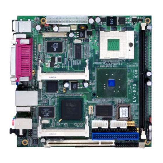
Chapter 1 <Introduction> 1.1 <Product Overview> LV-675 is the new generation of the Mini-ITX motherboard, with supporting last Intel Pentium M processors for 533/400MHz front side bus, Intel 845GV and ICH4 chipset, integrated graphics, DDR200/266/333 memory, REALTEK ALC 655 High Definition Audio, and one Intel 82541PI Gigabit LAN. -
Page 8: Product Specification
LV-675 User’s Manual 1.2 <Product Specification> General Specification Form Factor Mini-ITX motherboard Intel® Pentium M / Celeron M processors Package type: FC-PGA478 Front side bus: 400/533MHz Memory 1 x 184-pin DDR 200/266/333MHz SDRAM up to 1GB Unbufferred, none-ECC memory supported only Chipset Intel®... - Page 9 LV-675 User’s Manual Ethernet Interface Controller Intel 82541PI Gigabit Ethernet controller Type Triple speed 10/100/1000Base-T Auto-switching Fast Ethernet Full duplex, IEEE802.3U compliant Connector One External RJ45 connectors with LED on rear I/O panel Audio Interface Chipset Intel ICH4 with REALTEK ALC655 AC97 3D audio codec Interface 5.1 channel 3D audio with front (R/L), rear (R/L), center and bass...
-
Page 10: Mechanical Drawing
LV-675 User’s Manual 1.3 <Mechanical Drawing>... -
Page 11: Block Diagram
LV-675 User’s Manual 1.4 <Block Diagram> Intel Pentium M/Celeron M Processors Intel GMA Graphics LVDS/DVI CH7107 1 x 184-pin DDR 266/333MHz up to CH7009 845GV TV-OUT UltraDMA100 IDE ICH4 4 x USB2.0 ports Intel 82541PI Gigabit LAN REALTEK ALC 655... - Page 12 LV-675 User’s Manual (This Page is Left for Blank)
-
Page 13: Chapter 2
LV-675 User’s Manual Chapter 2 <Hardware Setup> 2.1 <Connector Location> CN_COM2 JCSEL1 JCSEL2 SYSFAN CN_IR JRTC JFRNT JDOM CN_USB1 IDE2 CPUFAN IDE1 PCI Slot CN_DIO CN_INV Mini PCI 2 (LV-675X Only) JVLCD CN_AUDIO (LV-675X Only CDIN JLAN CN_LVDS CN_COM1 CN_DVI... -
Page 14: Jumper Location & Reference
LV-675 User’s Manual 2.2 <Jumper Location & Reference> Jumper Function JRTC CMOS Operating/Clear Setting JVLCD Panel Voltage Setting (LV-675X Only) JLAN Enable/Disable on Board LAN function JDOM IDE1 Pin-20 voltage setting JRTC JDOM JLAN JVLCD... -
Page 15: Connector Reference
LV-675 User’s Manual 2.3 <Connector Reference> 2.3.1 <Internal Connectors> Connector Function Remark Socket478 for Intel Pentium M/Celeron M CPU Standard DIMM 184-pin DDR SDRAM DIMM socket Standard IDE1 40-pin IDE connector Standard IDE2 44-pin IDE connector Slim 26-pin slim type floppy connector... -
Page 16: Cpu And Memory Setup
LV-675 User’s Manual 2.4 <CPU and Memory Setup> 2.4.1 <CPU Setup> The board comes with the socket478 for Intel Pentium M/Celeron M processors, it supports new generation of Intel Pentium M processors with 400/533MHz of front side bus . Please follow the instruction to install the CPU properly. -
Page 17: Memory Setup
LV-675 User’s Manual 2.4.2 <Memory Setup> The board provides one 184-pin DDR DIMM to support DDR 200/266/333 memory modules up to 1GB of capacity. Non-ECC, unbuffered memory is supported only. 104-pin 80-pin Please check the pin number to match the socket side well... -
Page 18: Cmos Setup
LV-675 User’s Manual 2.5 <CMOS Setup> The board’s data of CMOS can be setting in BIOS. If the board refuses to boot due to inappropriate CMOS settings, here is how to proceed to clear (reset) the CMOS to its default values. -
Page 19: Ide Interface
LV-675 User’s Manual 2.6 <IDE Interface> The board has one UltraDMA100 IDE1 interface to support up to 2 ATAPI devices . The board has one UltraDMA33 IDE2 interface to support up to 2 ATAPI devices . IDE1 IDE2... -
Page 20: Enhanced Ide Interface
The Intel® ICH4 (south bridge chip) supports one enhanced IDE interface, dual channel for two ATAPI devices with ATA100. Based on this function, LV-675 has one 40-pin IDE connector with jumper selectable for pin-20 +5V supported. The jumper JDOM is two-pin type for pin-20 supplied with +5V to apply the DOM (Disk on Module). -
Page 21: Floppy Port
LV-675 User’s Manual 2.8 <Floppy Port> The board provides one slim type floppy port. Lift up the brown plastic bar Slot the cable in (Blue paste for brown bar side) Press back the plastic bar Floppy rear side Lift up this plastic bar... -
Page 22: Ethernet Interface
LV-675 User’s Manual 2.9 <Ethernet Interface> LV-675 integrates one Gigabit LAN interfaces with Intel 82541PI; it provide a standard IEEE 802.3 Ethernet interface for 1000BASE-T, 100BASE-TX and 10BASE-T applications. LV-675 provides one RJ45 connectors on the rear I/O panel. The JLAN can let you set to enable/disable the onboard LAN function. -
Page 23: Onboard Display Interface
LV-675 User’s Manual 2.10 <Onboard Display Interface> Based on Intel 845GV chipset with built-in graphics, the board provides one DB15 connector on real external I/O port, and one 40-pin LVDS interface with 5-pin LCD backlight inverter connector(LV-675X Only). The board provides dual display function with clone mode and extended desktop mode for CRT and LCD. -
Page 24: Lvds Display Lv-675X Only
LV-675 User’s Manual 2.10.2 <LVDS Display LV-675X Only > The board provides one 40-pin LVDS connector for 18/24-bit dual channel panels, supports up to 1600 x 1200 (UXGA) of resolution, with one LCD backlight inverter connector and one jumper for panel voltage setting. - Page 25 LV-675 User’s Manual Connector: CN_INV Connector: JVLCD Type: 5-pin LVDS Power Header Type: 3-pin Power select Header Description Description +12V VCC (5V) VCC/LDC VCC3 (3.3) ENABKL Connector: CN_LVDS Type: onboard 40-pin connector for LVDS connector Connector model: HIROSE DF13-40DP-1.25V Signal...
- Page 26 LCD Installation Guide: Preparing the LV-675, LCD panel and the backlight inverter. Please check the datasheet of the panel to see the voltage of the panel, and set the jumper JVLCD to +5V or +3.3V.
- Page 27 LV-675 User’s Manual After setup the devices well, you need to select the LCD panel type in the BIOS. The panel type mapping is list below: BIOS panel type selection form Single channel Dual channel Output format Output format 800 x 600 (18bit)
-
Page 28: Dvi Display Lv-675D Only
LV-675 User’s Manual 2.10.3 <DVI Display LV-675D Only > The board provides optional DVI-D interface with Intel 845GV, compliant with DVI 1.0 standard, and supports dual display (clone or extended desktop) function with CRT. Connector: CN_DVI Connector type: 26-pin header connector (pitch = 2.54mm) -
Page 29: S-Video Interface
LV-675 User’s Manual 12.10.4 <S-Video Interface> The board provides one S-Video interface up to 1024 x 768 resolution by NTSC/PAL supported, for three output types with Composite, S-Video and Component . Notice1: This connector is for both S-Video/Composite outputs; please use attached two cables in the package for SDTV devices. -
Page 30: Integrated Audio Interface
LV-675 User’s Manual 2.11 <Integrated Audio Interface> LV-675 integrated with REALTEK® ALC655 Codec for 5.1 channel sound output. It supports 16-bit stereo full-duplex with 48 KHz sampling rate, compliant with AC97 Rev.2.3 specifications. The board has one phone jack on rear I/O panel for Line-out, Line-in, MIC(stereo)-in as 2-channel sound system, and Front, Rear, Center as 5.1-channel sound system. - Page 31 LV-675 User’s Manual Connector: CN_AUDIO Type: 10-pin (2 x 5) 1.27mm x 2.54mm-pitch header Description Description Line in _L Ground Line in _R MIC1 MIC2 Ground Front_L Front_R Ground Connector: CDIN Type: 4-pin header (pitch = 2.54mm) Description CD – Left...
-
Page 32: Gpio Interface
LV-675 User’s Manual 2.12 <GPIO Interface> The board provides a programmable 8-bit digital I/O interface; you can use this general purpose I/O port for system control like POS or KIOSK. Connector: CN_DIO Type: 12-pin (6 x 2) 2.0mm pitch header... -
Page 33: Power Supply
LV-675 User’s Manual 2.13 <Power Supply> 2.13.1 <Power Input> The LV-675 provides a standard ATX power supply with 24-pin ATX connector . Connector: ATX Type: 24-pin ATX power connector PIN assignment 3.3V 3.3V 3.3V -12V PS_ON PW_OK 5V_SB 3.3V... -
Page 34: Switch And Indicator
LV-675 User’s Manual 2.14 <Switch and Indicator> The JFRNT provides front control panel of the board, such as power button, reset and beeper, etc. Please check well before you connecting the cables on the chassis. Connector: JFRNT Type: onboard 14-pin (2 x 7) 2.54-pitch header... -
Page 35: Chapter 3
LV-673 User’s Manual Chapter 3 <System Setup> 3.1 <Video Memory Setup> Based on Intel® 845GV chipset , the board supports Intel® DVMT (Dynamic Video Memory Technology) 3.0, which would allow the video memory to be allocated up to 64MB. To support DVMT, you need to install the Intel GMA Driver with supported OS. BIOS Setup: On-Chip Video Memory Size: This option combines three items below for setup. -
Page 36: Chapter 4
LV-675 User’s Manual Chapter 4 <BIOS Setup> The motherboard uses the Award BIOS for the system configuration. The Award BIOS in the single board computer is a customized version of the industrial standard BIOS for IBM PC AT-compatible computers. It supports Intel x86 and compatible CPU architecture based processors and computers. - Page 37 LV-675 User’s Manual (This Page is Left for Blank)
-
Page 38: Appendix A
LV-675 User’s Manual Appendix A <I/O Port Pin Assignment> A.1 <IDE Port> Connector: IDE1 Type: 40-pin (20 x 2) box header Description Description Reset Ground Ground Ground IOW-/STOP Ground IOR-/HDMARDY Ground IORDY/DDMARDY IDESEL DACK- Ground P66DET CS0 (MASTER CS) CS1 (SLAVE CS) - Page 39 LV-675 User’s Manual Connector: IDE2 Type: 44-pin (22 x 2) box header Description Description Reset Ground Ground Ground -IOW Ground -IOR Ground IORDY IDSEL DACK Ground IDEIRQ IDE32 P66DET -CS1 -CS3 -HD LED1 Ground Ground Ground...
-
Page 40: A.2
LV-675 User’s Manual A.2 <Floppy Port> Connector: FDD Type: 26-pin connector Description Description INDEX DSKCH MTR0 DRVDE0 STEP Ground WRITE DATA Ground WRITE GATE Ground TRACK 0 WRPRO Ground RDATA- Ground A.3 <IrDA Port> Connector: CN_IR Type: 5-pin header for SIR Ports... -
Page 41: A.4
LV-675 User’s Manual A.4 <Serial Port> Connector: COM1/COM2 Type: 9-pin D-sub male connector on bracket Description Description DCD- DSR- SIN- RTS- CTS- DTR- Ground A.5 <VGA Port> Connector: VGA Type: 15-pin D-sub female connector on bracket Description Description Description Ground... -
Page 42: A.7 < Usb Interface
LV-675 User’s Manual A.7 < USB Interface > Connector: CN_USB Type: 10-pin (5 x 2) header for dual USB Ports Description Description Data0- Data1- Data0+ Data1+ Ground Ground Ground A.8 < LPT Port > Connector : LPT Type :26-Pin D-Sub female Connector on bracket... -
Page 43: Appendix B
LV-675 User’s Manual Appendix B <Flash BIOS> B.1 <Flash Tool> The board is based on Award BIOS and can be updated easily by the BIOS auto flash tool. You can download the tool online at the address below: http://www.phoenix.com/en/home/ http://www.commell.com.tw/Support/Support_SBC.htm File name of the tool is “awdflash.exe”, it’s the utility that can write the data into the... -
Page 44: Appendix C
LV-675 User’s Manual Appendix C <System Resources> C1.<I/O Port Address Map>... - Page 45 LV-675 User’s Manual...
- Page 46 LV-675 User’s Manual C2.<Memory Address Map>...
- Page 47 LV-675 User’s Manual C3.<System IRQ & DMA Resources> DMA: IRQ:...
- Page 48 LV-675 User’s Manual The GPIO’can be programmed with the MSDOS debug program using simple IN/OUT commands.The following lines show an example how to do this. GPIO0…..GPIO7 bit0……bit7 -o 2E 87 ;enter configuration -o 2E 87 -o 2E 29 -o 2E 40 ;enale GPIO function...
-
Page 49: Appendix D
LV-675 User’s Manual Appendix D <Display Setting> Before you using your display device: 1. Check your software Before you can use the display device properly, please install the VGA drivers. 2. Check your hardware Please setup the display device properly before you boot up the system. - Page 50 LV-675 User’s Manual 4. There will be a different device list depends on your connecting devices For Monitor: You can configure the Colors, Screen area (resolution) and Refresh Rate. For Notebook: If you connect a LCD panel though LVDS interface, you can configure the Colors...
- Page 51 LV-675 User’s Manual Appendix E <How to choose RS-422 & Rs-485> JCSEL1 JCSEL1 JCSEL1 RS-485 RS-232 RS-422 JCSEL2 JCSEL2 JCSEL2 JCSEL2 JCSEL1...
- Page 52 LV-675 User’s Manual Appendix F <Programming Watchdog Timer > The watchdog timer makes the system auto-reset while it stops to work for a period. The integrated watchdog timer can be setup as system reset mode by program. Timeout Value Range...
-
Page 53: Contact Information
LV-675 User’s Manual Contact Information Any advice or comment about our products and service, or anything we can help you please don’t hesitate to contact with us. We will do our best to support you for your products, projects and business.
Need help?
Do you have a question about the LV-675 and is the answer not in the manual?
Questions and answers