
Subscribe to Our Youtube Channel
Related Manuals for HP 409054-003


Summary of Contents for HP 409054-003
-
Page 1: Hp Ip Console Switch With Virtual Media
HP IP Console Switch with Virtual Media User Guide Part Number 409054-003 August 2008 (Third Edition) -
Page 2: Intended Audience
© Copyright 2006, 2008 Hewlett-Packard Development Company, L.P. The information contained herein is subject to change without notice. The only warranties for HP products and services are set forth in the express warranty statements accompanying such products and services. Nothing herein should be construed as constituting an additional warranty. HP shall not be liable for technical or editorial errors or omissions contained herein. -
Page 3: Table Of Contents
Cascading console switches matrix ... 23 Cascading two HP Server Console Switches with Virtual Media and an HP IP Console Switch with Virtual Media 24 Example of an HP Server Console Switch with Virtual Media and an HP IP Console Switch with Virtual Media cascade configuration... - Page 4 Upgrading the console switch firmware overview ... 78 Upgrading the console switch firmware through the local OSD... 78 Upgrading the console switch firmware through the HP IP Console Viewer... 80 Upgrading the console switch firmware through the serial management connection ... 80 Upgrading interface adapter firmware ...
- Page 5 How do I cascade console switches? ... 92 How do I change the keyboard language? ... 92 How do I know which port my cascaded console switch is connected to? ... 92 How do I locally connect a cascaded console switch?... 93 How do I look at my console switch firmware version? ...
-
Page 6: Component Identification
Component identification Console switch components Item Description Power cord connector Power switch Fans Activity indicator light LAN connector (10/100/1000 gigabit) Serial management connector Mouse connector for local user Keyboard connector for local user Video connector for local user USB ports... -
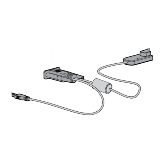
Page 7: Interface Adapter With Virtual Media Components
Interface adapter with Virtual Media components Interface adapters that support Virtual Media have two LEDs on the front of the RJ-45 connector. Item Description When lit, this LED indicates that the interface adapter has power from the server. When lit, this LED indicates that there is an active console session with the interface adapter. - Page 8 Item Description RJ-45 connector USB connector PS2 interface adapter with Virtual Media Item Description Video connector RJ-45 connector USB connector (for Virtual Media only) Mouse connector Keyboard connector Component identification 8...
-
Page 9: Installing The Console Switch
Begin installing the equipment at the bottom of the rack cabinet, and then work to the top. Avoid uneven loading or overloading of the rack cabinets. Rack-mount safety instructions When rack-mounting a console switch, consider the following factors: • Elevated operating ambient temperature—If the equipment is installed in a closed or multi-unit rack assembly, the operating ambient temperature of the rack environment might be greater than room ambient temperature. -
Page 10: Required Items Not Included
Cage nut insertion tool (included with your original rack hardware kit) Rack-mounting the console switch NOTE: Before installing the console switch into the rack, connect the console switch to a power source, using the power cords provided, and power on the unit. An activity indicator light ("Console switch... -
Page 11: Performing A Side-Mount Type A Installation
Remove the four screws, two on each side, from the console switch. Attach the side-mounting brackets to the console switch using the four screws that you removed. Slide the side-mounting bracket tabs into the U locations on each side of the rack. -
Page 12: Performing A Side-Mount Type B Installation
Secure the console switch to the rails using four self-tapping screws, two on each side. Performing a side-mount type B installation Remove the four screws, two on each side, from the console switch. Attach the side-mounting brackets to the console switch using the four screws that you removed. -
Page 13: Performing A Standard-Mount Installation
Slide the side-mounting bracket tabs into the U locations on each side of the rack. Install four cage nuts into the side-mounting bracket U locations. Secure the console switch to the rails, using four M-6 screws, two on each side. Performing a standard-mount installation Remove the four screws, two on each side, from the console switch. - Page 14 Attach the 1U brackets to the console switch using the four screws that you removed. Install a cage nut behind each rear rail, if the cage nuts have not already been installed. Installing the console switch 14...
-
Page 15: Performing A Cantilever-Mount Type A Installation
Slide the console switch behind the rear of the 1U product. Secure the console switch to the rails using two M-6 screws, one on each side. Performing a cantilever-mount type A installation Remove the four screws, two on each side, from the console switch. - Page 16 Attach the 1U brackets to the console switch using the four screws that you removed. Install up to six clip nuts. Installing the console switch 16...
-
Page 17: Performing A Cantilever-Mount Type B Installation
Secure the console switch to the rails, using the appropriate number of T-25 Torx screws. Performing a cantilever-mount type B installation Remove the four screws, two on each side, from the console switch. Attach the 1U brackets to the console switch using the four screws that you removed. -
Page 18: Connecting The Console Switch
Install up to six cage nuts. Secure the console switch to the rails using the appropriate number of M-6 screws. Connecting the console switch Connect the local keyboard, video, and mouse to the console switch. Installing the console switch 18... - Page 19 UTP CAT7 cables may also be used. Connect a UTP CAT5 cable to the LAN connector on the console switch. Connect the other end of that same UTP CAT5 cable to an Ethernet switch. The following figure shows one possible configuration for your console switch system.
-
Page 20: Hp Ip Console Viewer Overview
HP IP Console Viewer overview You must install the HP IP Console Viewer software if you want to use the software to configure the console switch. The HP IP Console Viewer enables you to view and control a server attached to the console switch system, configure and maintain the system, and prevent unauthorized access to the console switch through IP connections. -
Page 21: Installing The Interface Adapter
Interface adapter overview An interface adapter is required for the console switch system to function properly. However, an interface adapter is not included in the console switch kit. The interface adapter is connected to a console switch using a CAT5 cable. - Page 22 Item Description Server Console switch USB 2.0 interface adapter with Virtual Media PS2 interface adapter with Virtual Media Installing the interface adapter 22...
-
Page 23: Cascading Console Switches
As shown in the following table, for Virtual Media to work properly in a two-level cascade configuration, you must have an HP Server Console Switch with Virtual Media or an HP IP Console Switch with Virtual Media as the main console switch and an HP Server Console Switch with Virtual Media as the secondary console switch. -
Page 24: Cascading Two Hp Server Console Switches With Virtual Media And An Hp Ip Console Switch With Virtual Media
Virtual Media and an HP IP Console Switch with Virtual Media The following figure shows two HP Server Console Switches with Virtual Media cascaded to an HP IP Console Switch with Virtual Media. The top console switch is the main console switch, the middle console switch is the secondary console switch, and the bottom console switch is the tertiary console switch. - Page 25 Upgrade the console switch and interface adapter firmware 78). Connect a UTP CAT5 cable to the server connection port on the main console switch. Connect the other end of that same UTP CAT5 cable to the RJ-45 tiering connector on the secondary console switch.
-
Page 26: Example Of An Hp Server Console Switch With Virtual Media And An Hp Ip Console Switch With Virtual Media Cascade Configuration
Example of an HP Server Console Switch with Virtual Media and an HP IP Console Switch with Virtual Media cascade configuration Item Description Servers Cascading console switches 26... - Page 27 Item Description Main console switch (HP IP Console Switch with Virtual Media) Interface adapters (USB 2.0 interface adapter with Virtual Media or PS2 interface adapter with Virtual Media) UTP CAT5 cable UTP CAT5 cable Local console KVM cables Local console...
-
Page 28: Local Port Operation
Local port operation overview The console switch system has one local port on the rear panel that enables you to connect a keyboard, monitor, and mouse to the console switch for direct access. Use the Main dialog box servers in the console switch system. You can also clear offline interface adapters by clicking the Clear button. -
Page 29: Viewing Servers By Name, Eid, Or Port
Viewing the server status column The status of the servers in the console switch system is indicated by the icons in the right column of the Main dialog box ("Accessing the Main dialog... -
Page 30: Soft Switching
Soft switching Soft switching is the ability to switch servers using a hotkey sequence. You can soft switch to a server by pressing the Print Scrn key, entering the first few characters of the server's name or port number, and pressing the Enter key. -
Page 31: Managing Routine Tasks For Servers
Caps Lock Managing routine tasks for servers You can configure the console switch and manage routine tasks for your servers from the Setup dialog box within the OSD. To identify servers by unique names, click Names when initially setting up your console switch. -
Page 32: Changing The Display Behavior
Flag Changes the type of display, timing, color, and location of the status flag. Devices Changes the device type from a server to a console switch and identifies the number of ports on the console switch. Keyboard Changes the keyboard country code reported by the interface adapter. -
Page 33: Selecting The Display Order Of Servers
To access the Menu dialog, from the Main dialog box click Setup>Menu. The Menu dialog box appears. Selecting the display order of servers From the Menu dialog box, select Name to display servers alphabetically by name. -or- Select EID to display servers numerically by interface adapter ID number. -or- Select Port to display servers numerically by port number. -
Page 34: Changing The Status Flag
Flag Changing the status flag From the Main dialog box Flag Setup dialog box appears. Select Name or EID to determine what information appears on the flag in the Flag Type area. Select Displayed (default) to show the flag constantly, and select Timed to display the flag for only five seconds after soft switching. -
Page 35: Assigning Device Types
For example, if the console switch is connected to port 02, the switch port is listed as 02, and each server shown under it is numbered sequentially 02-01, 02-02, and so on. -
Page 36: Changing The Keyboard Language
Changes made in the Device Modify dialog box are not saved until you click OK in the Devices dialog box. Changing the keyboard language You can select the keyboard language for all USB interface adapters connected to the console switch. From the Main dialog box The Keyboard dialog box appears. -
Page 37: Changing Network Configurations
The console switch system uses IP addresses to uniquely identify the console switches and computers running the HP IP Console Viewer. HP recommends that IP addresses be reserved for each unit and that they remain static while the console switches are connected to the network. - Page 38 Use the Security dialog box to lock your console switch with password protection, set or change the password, and enable the screen saver. If a password has been previously set, you must enter the password before you can access the Security dialog box. You do not have to set a screen saver password.
- Page 39 474-6836), a 16-bit key, and the EID number of the console switch. Call the HP technical support phone number. Give the service person your 16-bit key and EID number of the console switch. A one-time unlock code, which is specific to your console switch, is given to you.
- Page 40 Security dialog box. Click OK to start the screen saver test. Logging in to the console switch (after Screen Saver mode has been enabled) Press any key on the keyboard, or move the mouse. The Authorize dialog box appears. Enter the password, and then click OK.
- Page 41 Removing screen saver password protection From the Main dialog box Authorize dialog box appears. ("Setting local console switch security" on page 37), clear the Enable ("Accessing the Main dialog box" on page 28), click Setup>Security. The...
-
Page 42: Exiting Screen Saver Mode
Enter the console switch password, and then click OK. The Security dialog box appears. Double-click the New field, leave the New field blank, and press the Enter key. Double-click the Repeat field, leave the Repeat field blank, and press the Enter key. -
Page 43: Changing The Osd Language
("Installing the interface server to another console switch port, the console switch still recognizes the names and configurations. To access the Names dialog box, from the Main dialog box 28), click Setup>Names. The Names dialog box appears. -
Page 44: Assigning Names To Servers
Setting up a scan pattern In Scan mode ("Activating Scan (server to server). ("Assigning server and serial device mode" on page 46), the console switch automatically scans port to port names" on page 43), select the Local port operation 44... -
Page 45: Adding Servers To The Scan List
Double-click a server name or port. You can select up to 100 servers from a list of all servers attached to the console switch. You can display the list by either name or EID number by clicking the appropriate button. Selecting the checkbox beside each server to be added to the scan list creates the scan list. -
Page 46: Removing Servers From The Scan List
Click OK to save settings, or click Clear to remove all servers from the scan list. Removing servers from the scan list From the Scan dialog box double-click a server name or port, or click Clear to remove all servers from the scan list. Click OK to save settings. -
Page 47: Assigning A Preempt Timeout
(remote or local) user who has a lesser or equal access level. Depending on the access level of the user issuing the preemption request and that of the user being preempted, the preemption request can be rejected. The Override Admin account is treated as a Console Switch Administrator in the following table. User level... -
Page 48: Managing Server Tasks Using The Osd
These messages appear for the time assigned in the Timeout Seconds field set through either the local OSD or the HP IP Console Viewer. If the user you are preempting does not respond within the selected time, the user is disconnected and the preemption is granted. -
Page 49: Viewing And Disconnecting User Connections
Displays users and Virtual Media sessions and enables you to disconnect users and Virtual Media sessions. Upgrades multiple interface adapters simultaneously. Displays version information and enables you to upgrade console switch and interface adapter firmware. Displays settings. Validates the integrity of your system, including firmware CRC and interface adapters. -
Page 50: Viewing Current User Connections
Viewing current user connections From the Main dialog box The User Status dialog box appears. Disconnecting a user From the Main dialog box Status. The User Status dialog box appears. Click the letter of the user to be disconnected. The Disconnect dialog box appears. Click Disconnect to disconnect the user and return to the User Status dialog box, click X to exit, or press the Esc key to exit the dialog box without disconnecting a user. -
Page 51: Displaying Interface Adapter Status Information
To access the IA Status dialog box, from the Main dialog box, click Commands>IA Status. The IA Status dialog box appears. Displaying version information NOTE: Provide the application version number when communicating with HP customer service centers. The Versions dialog box enables you to view the console switch versions. To access the Version dialog box:... - Page 52 ("Accessing the Main dialog Commands>Versions. The Version dialog box appears. The top half of the box lists the subsystem versions in the console switch. Click IA to access the IA Select dialog box to view individual interface adapter version information.
-
Page 53: Decommissioning An Interface Adapter
Click Decommission. The associated server names, number of cascade ports, country code and keyboard and mouse settings are set back to the factory defaults. Displaying configuration information The Config dialog box enables you to view the console switch configurations. ("Accessing the Main dialog box" on page 28), click Commands>IA... -
Page 54: Running System Diagnostics
To access the Config dialog box, from the Main dialog box 28), click Commands>Config. The Config dialog box appears. Running system diagnostics You can validate the firmware CRCs and interface adapter status for the console switch through the Run Diagnostics command. To access the Diagnostics dialog box, click Commands>Run Diagnostics. -
Page 55: Activating Run Diagnostics
Test LAN Connection (digital only) On-line IAs Offline IAs Suspect IAs Activating Run Diagnostics From the Main dialog box Diagnostics. A warning message appears, indicating that all users will be disconnected. Perform one of the following actions: Click OK to begin. All users are disconnected, and the Diagnostics dialog box appears. Click X or press the Esc key to exit the dialog box without running a diagnostic test. -
Page 56: Resetting Devices
When each test is finished, a pass or fail symbol appears. A passed test is indicated with a green circle, and a failed test is indicated by a red X. The test is complete when the last test symbol appears. (Optional) If you have any offline interface adapters, click Clear to remove them from the list. - Page 57 From the Main dialog box ("Accessing the Main dialog Commands dialog box appears. Click Device Reset. A warning appears, and the device is reset. box" on page 28), click Commands. The Local port operation 57...
-
Page 58: Using Virtual Media
You can also add and map an .iso or floppy image file on the local client as a virtual drive on the target server if you are using the HP IP Console Viewer. -
Page 59: Virtual Media Resources
For local Virtual Media to work properly, you must have an HP Server Console Switch with Virtual Media or an HP IP Console Switch with Virtual Media as the console switch. You must also have an interface adapter with Virtual Media connecting each server to the console switch. -
Page 60: Using Virtual Media In A Two-Level Cascade Configuration
For Virtual Media to work properly in a two-level cascade configuration, you must have an HP Server Console Switch with Virtual Media or an HP IP Console Switch with Virtual Media as the main console switch and an HP Server Console Switch with Virtual Media as the secondary console switch. You must also have an interface adapter with Virtual Media connecting each server to the console switch. -
Page 61: Using Virtual Media In A Three-Level Cascade Configuration
For Virtual Media to work properly in a three-level cascade configuration, you must have an HP Server Console Switch with Virtual Media or an HP IP Console Switch with Virtual Media as the main console switch and an HP Server Console Switch with Virtual Media as the secondary and tertiary console switches. -
Page 62: Connecting Local Virtual Media
Connecting local Virtual Media You can connect Virtual Media directly to the console switch using one of the USB ports located on the console switch. You can have only one CD-type and one mass-storage-type device mapped concurrently. All USB ports of a local console are assigned to a single KVM session and cannot be mapped independently. -
Page 63: Using Usb Composite Media Devices
USB 2.0 function of the USB 2.0 interface adapter with Virtual Media from the console switch local OSD, allowing the interface adapter to operate in 1.1 mode. You should limit the interface adapter to USB 1.1 speed only if the interface adapter functionality is not working properly. The... - Page 64 ("Accessing the Main dialog Commands>Versions. The Version dialog box appears. The top half of the box lists the subsystem versions in the console switch. Click IA to access the IA Selection dialog box to view individual interface adapter version information. The IA Select dialog box appears.
-
Page 65: Enabling The Usb 2.0 Function
If your target server BIOS or operating system supports USB 2.0 devices and you disabled the USB 2.0 function of the USB 2.0 interface adapter with Virtual Media from the console switch local OSD, which enables the interface adapter to operate in USB 1.1 mode, you can enable USB 2.0 mode for that server. - Page 66 ("Accessing the Main dialog Commands>Versions. The Version dialog box appears. The top half of the box lists the subsystem versions in the console switch. Click IA to access the IA Selection dialog box to view individual interface adapter version information. The IA Select dialog box appears.
- Page 67 To view the selected interface adapter, click Version. The IA Version dialog box appears. When the USB 2.0 interface adapter with Virtual Media or the PS2 interface adapter with Virtual Media are in USB 1.1 mode, the Enable button appears. Click Enable to force the interface adapter into USB 2.0 mode.
-
Page 68: Console Switch Serial Management
Connect the network cable from the LAN port on the rear panel of the console switch to an Ethernet switch, and power on the console switch. For more information, see the HP IP Console Viewer User Guide included on the CD provided with this kit. -
Page 69: Configuring Minicom
Select the Communication Port that is connected to the console switch through a serial cable, then click OK. The COM1 Properties window appears. Select 9600 for the Bits Per Second, 8 for Data Bits, None for Parity, 1 for Stop Bits, and None for Flow Control, then click OK. -
Page 70: Network Configuration
Establish a terminal session, and then press Enter. The Main Menu appears. Network Configuration The Network Configuration option provides different settings to configure your network. For more information, see "Configuring the console switch NIC." Firmware Management The Firmware Management option updates the firmware using a TFTP or FTP server. -
Page 71: Restore Factory Defaults
The Restore Factory Defaults option enables you to delete all settings and restore all parameters in the configuration to factory defaults. Reset Appliance The Reset Appliance option reboots the server console switch. Enable LDAP Debug Messages The Enable LDAP Debug option enables you to disable LDAP debug messages. -
Page 72: Input Web Server Certificate
Input Web Server Certificate The Input Web Server Certificate option enables you to update the web server security certificate. Exit The Exit option allows you to exit the Main Menu. Console switch serial management 72... -
Page 73: Configuring The Console Switch Nic
Configuring the console switch NIC Establish a terminal session and then press the Enter key. The Main Menu appears. Console switch serial management 73... - Page 74 Select Option 1—Network Configuration. The Network Configuration Menu appears. Select Option 1—Network Speed to set the network speed. When possible, set the connection manually without relying on the auto negotiate feature. After you enter a selection, return to the Network Configuration menu. Console switch serial management 74...
- Page 75 If you are using a BootP address, configure the BootP server to provide an IP address to the console switch, and then continue to step 7. If you are using a static IPv4 address, perform the following steps: To specify an IP address, select Option 3—IP Address.
-
Page 76: Recovering A Lost Console Switch Serial Management Password
Recovering a lost console switch serial management password Establish a terminal session, and press the Enter key. You are prompted to enter the console switch serial management password. Enter HELP. A 16-bit key and the EID number of the console switch appear. - Page 77 Call the HP technical support phone number (1-800-474-6836). Give the service person your 16-bit key and EID number of the console switch. A one-time password, which is specific to your console switch, is given to you. Enter the one-time password. Your previous console switch serial management password is deleted.
-
Page 78: Upgrading The Firmware
Also, be sure that the console switch is on the same network as the computer that is being used for the upgrade. After the TFTP has been enabled, then upgrade the console switch firmware. - Page 79 Click Upgrade. The Warning dialog box appears. Click OK. The Download dialog box appears. Use one of the following methods to perform the upgrade: Select TFTP. Enter the TFTP IP address and the TFTP file name, and then click Download. Select FTP.
-
Page 80: Upgrading The Console Switch Firmware Through The Hp Ip Console Viewer
Upgrading the console switch firmware through the HP IP Console Viewer To upgrade the firmware for through the HP IP Console Viewer, follow the instructions in the \TFTP\TFTP Install Instructions.txt file on the CD included with this kit or the Softpaq TFTP directory. - Page 81 If the supplied power cord is not already connected, plug it into the power cord connector switch components" on page 6) on the console switch, and then plug it into a valid power source. Power on the console switch, if it is not already powered on. The activity indicator light switch components"...
-
Page 82: Upgrading Interface Adapter Firmware
Do not cycle power to the console switch during this process. A loss of power might render the console switch inoperable and require that the unit be returned to the factory for repair. Be patient; the update can take as long as 10 minutes. -
Page 83: Loading Interface Adapter Firmware Individually
NOTE: This method of loading the interface adapter firmware will always overwrite the current version of firmware in the interface adapter. HP recommends upgrading your interface adapters simultaneously 84), which only upgrades interface adapters needing a new version of firmware. -
Page 84: Upgrading The Interface Adapter Firmware Simultaneously
Select the individual interface adapter, and click Version. The IA Version dialog box appears. Click Load Firmware. The IA Load dialog box appears. Click OK. Upgrading the interface adapter firmware simultaneously From the Main dialog box Status. The IA Status dialog box appears. ("Accessing the Main dialog box"... -
Page 85: Upgrading The Interface Adapter Firmware Through The Autoupdate Feature
Wait until the OSD indicators are green before continuing. Upgrading the interface adapter firmware through the autoupdate feature You can automatically upgrade the interface adapter firmware when the console switch is upgraded or when a new interface adapter is discovered. To enable the autoupgrade feature: From the Main dialog box Status. -
Page 86: Enabling Tftp For Microsoft Windows Operating Systems
Enabling TFTP for Microsoft Windows operating systems To enable TFTP for Microsoft® Windows® operating systems, follow the instructions in the \TFTP\TFTP Install Instructions.txt file on the CD included with this kit or the Softpaq TFTP directory. Enabling TFTP for Linux operating systems TFTP is provided by the TFTP server RPM (RPM-IVH/Redhat/RPMS/) for most systems using RPM packages. - Page 87 From the shell prompt, enter tftp localhost (or name of local system). Download the file by entering the following command: get/tftpboot/filename Enter quit. From the shell prompt, check to see if the file is in the /tmp directory. If the TFTP is configured correctly, the preceding steps transfer the file to the current directory. Upgrading the firmware 87...
-
Page 88: Troubleshooting
Be sure that the monitor supports the refresh rate to which target server is set. • Be sure that the console switch is powered on and that the power source is valid. • Be sure that the cables are properly connected. - Page 89 Be sure that the interface adapter connectors are connected to the correct ports on the attached servers. Be sure that the correct interface adapters are being used. You can only use HP interface adapters with this product. Be sure that a UTP CAT5 cable is connected from the RJ-45 connector on the interface adapter to the appropriate server connector on the rear panel of the console switch.
-
Page 90: Connection Length Table
The console switch offers optimum video performance when the distance between the server and console switch is 22.9 m (75 ft) or less at video resolutions 1280 x 1024 at 75 Hz. The system is capable of operation at distances up to 30.5 m (100 ft) at reduced video resolutions 800 x 640 at 60 Hz, worst case. -
Page 91: Frequently Asked Questions
Yes. Can the console switch be mounted in a round-hole rack? Yes, the console switch can be mounted in a round-hole rack using the standard-mount installation. Can the console switch be side-mounted in a round- hole rack? Has the customer verified the firmware version? IMPORTANT: any operations. -
Page 92: How Do I Access The Main Dialog Box
51) and interface adapter firmware version Upgrade the console switch firmware, interface adapter firmware firmware" on page 82), and cascaded console switch firmware if you do not have the latest versions installed. How do I access the Main dialog box? Press the Print Scrn key. -
Page 93: How Do I Locally Connect A Cascaded Console Switch
Refer to "Running System Diagnostics (on page 54)." Is the console switch operational? Ask the customer to connect the KVM cables to the appropriate connectors components" on page 6) on the rear panel of the console switch. Power on the console switch. Does the activity indicator light console switch light up? If the activity indicator light is on, the console switch is operational. -
Page 94: What Are The Minimum And Maximum Cable Lengths
After the activity indicator light is on, which means the console switch is operational, ask the customer to press the Prnt Scrn key on the keyboard attached to the monitor that is connected to the console switch (local port). The Main menu appears and if no servers are connected, the screen is blank. -
Page 95: Technical Support
(http://welcome.hp.com/country/us/en/wwcontact.html). For HP technical support: • In the United States, for contact options see the Contact HP United States webpage (http://welcome.hp.com/country/us/en/contact_us.html). To contact HP by phone: Call 1-800-HP-INVENT (1-800-474-6836). This service is available 24 hours a day, 7 days a week. -
Page 96: Regulatory Compliance Notices
Regulatory compliance notices Regulatory compliance identification numbers For the purpose of regulatory compliance certifications and identification, this product has been assigned a unique regulatory model number. The regulatory model number can be found on the product nameplate label, along with all required approval markings and information. When requesting compliance information for this product, always refer to this regulatory model number. -
Page 97: Modifications
Hewlett-Packard Company P. O. Box 692000, Mail Stop 530113 Houston, Texas 77269-2000 • 1-800-HP-INVENT (1-800-474-6836). (For continuous quality improvement, calls may be recorded or monitored.) For questions regarding this FCC declaration, contact us by mail or telephone: • Hewlett-Packard Company P. -
Page 98: Disposal Of Waste Equipment By Users In Private Households In The European Union
This marking is valid for non-Telecom products and EU harmonized Telecom products (e.g. Bluetooth). This marking is valid for EU non-harmonized Telecom products. *Notified body number (used only if applicable—refer to the product label) Hewlett-Packard GmbH, HQ-TRE, Herrenberger Strasse 140, 71034 Boeblingen, Germany Disposal of waste equipment by users in private households in the European Union This symbol on the product or on its packaging indicates that this product must not be disposed... -
Page 99: Korean Class A Notice
Korean class A notice Power cord statement for Japan Regulatory compliance notices 99... -
Page 100: Acronyms And Abbreviations
Bootstrap Protocol cyclic redundant checks electronic identification number file transfer protocol GNOME GNU Network Object Model Environment HP SIM HP Systems Insight Manager interface adapter Internet Protocol keyboard, video, and mouse local-area network light-emitting diode network interface controller Acronyms and abbreviations 100... - Page 101 on-screen display peripheral component interface Red Hat Package Manager Systems Insight Manager SLES SUSE Linux Enterprise Server Transmission Control Protocol TFTP Trivial File Transfer Protocol universal serial bus unshielded twisted pair video graphics array Acronyms and abbreviations 101...
-
Page 102: Index
23, 92, 93 cascading console switches matrix 23 cascading console switches, overview 23 cascading two HP Server Console Switches with Virtual Media and an HP IP Console Switch with Virtual Media 24 certificate, input web server 72 changing keyboard language 36... - Page 103 Federal Communications Commission (FCC) notice 96, 97 firmware management 70 firmware, loading interface adapter individually 83 firmware, upgrade 78, 84 firmware, upgrading console switch through the HP IP Console Viewer 80 firmware, upgrading interface adapter 82 firmware, upgrading interface adapter through autoupdate 85...
- Page 104 OSD, managing server tasks 48 OSD, navigation keys 30 overview of installation process 9 overview, cascading console switches 23 overview, HP IP Console Viewer 20 overview, interface adapter 21 overview, local port operation 28 overview, upgrading firmware 78 password protecting the console switch 39...
- Page 105 78 upgrading console switch firmware through the HP IP Console Viewer 80 upgrading console switch firmware through the local OSD 78 upgrading console switch through the serial management connection 80 upgrading interface adapter firmware 82 upgrading interface adapter firmware...
Need help?
Do you have a question about the 409054-003 and is the answer not in the manual?
Questions and answers