HP ProCurve 408 Installation Manual
Hide thumbs
Also See for ProCurve 408:
- Installation manual (62 pages) ,
- Quick reference manual (44 pages) ,
- Specifications (2 pages)
Table of Contents
Advertisement
Advertisement
Table of Contents

Related Manuals for HP ProCurve 408


Summary of Contents for HP ProCurve 408
- Page 1 Installation Guide ProCurve Switch 408 www.procurve.com...
- Page 3 ProCurve Switch 408 Installation Guide...
- Page 4 Hewlett-Packard. consequential damages in connection with the furnishing, performance, or use of this material. Publication Number The only warranties for HP products and 5991-6250 services are set forth in the express February 2007 warranty statements accompanying such products and services.
-
Page 5: Table Of Contents
Contents 1 Introducing the Switch 408 Front of the Switch ....... . . 1-2 Network Ports . - Page 6 3 Troubleshooting Basic Troubleshooting Tips ......3-1 Diagnosing With the LEDs ......3-3 Hardware Diagnostic Tests .
- Page 7 Hinweise zur Sicherheit ......C-4 Considerazioni sulla sicurezza ..... . C-5 Consideraciones sobre seguridad .
- Page 8 —This page is intentionally unused—...
-
Page 9: Introducing The Switch 408
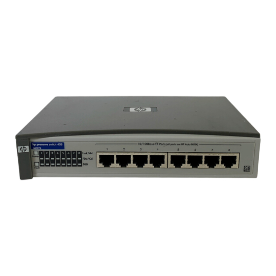
Introducing the Switch 408 The ProCurve Switch 408 is a multiport switch that can be used to build high-performance switched workgroup networks. This switch is a store-and-forward device that offers low latency for high-speed networking. ProCurve Switch 408 (J4097C) Throughout this manual, the name of this switch will be abbreviated as the Switch 408. -
Page 10: Front Of The Switch
Network Ports The switch has eight auto-sensing 10/100Base-TX ports with RJ-45 connectors. All of the ports have the HP Auto- MDIX feature, which means that either a straight-through or cross-over cable can be used for any connection to another device, and the switch automatically... -
Page 11: Leds
Introducing the Switch 408 Front of the Switch LEDs Table 1-1. Switch LEDs Switch LEDs State Meaning The switch is receiving power. (green) The switch is NOT receiving power. Fault The normal state; indicates that there are no fault (orange) conditions on the switch. -
Page 12: Back Of The Switch
AC power adapter is plugged in to an active power source and to the switch. Caution Use only the AC power adapter supplied with the switch. Use of other adapters, including adapters that came with other HP network products, may result in damage to the equipment. -
Page 13: Features
■ sense the connection speed, 10 Mbps or 100 Mbps, and automat- ically operate at that speed HP Auto-MDIX on all ports—all ports allow you to use either a ■ straight-through or crossover cable to connect to any other RJ-45 network device. There are no switches or buttons to deal with, and no more worrying about what type of cable is needed to connect to an end node, or to another switch or hub. - Page 14 Introducing the Switch 408 Switch Operation Overview matically and stored in the Switch 408’s 1000-entry address table. The switch also identifies the number of the port on which each address is learned so it knows the relative network location of each device. Forwarding, Filtering, Flooding.
-
Page 15: Installing The Switch 408
7210) is also available that provides a variety of mounting options including in a standard 19-inch EIA equipment rack or cabinet, on a wall, or under a horizontal surface. Contact your HP Networking products reseller to order the mounting kit. -
Page 16: Japan Power Cord Warning
Installing the Switch 408 Installation Procedures Japan Power Cord Warning Installation Procedures Summary Follow these easy steps to install your switch. The rest of this chapter provides details on these steps. Prepare the installation site. Make sure of the following: •... -
Page 17: Installation Precautions
Installing the Switch 408 Installation Procedures Connect the network devices. Using the appropriate network cables, connect computers, servers, printers and other periph- erals, and other network devices including other switches, hubs, or routers to the switch ports. See page 2-9. At this point, the switch is fully installed and your network should be up and running. - Page 18 Installing the Switch 408 Installation Procedures ■ If you rack mount the Switch 408 (using the mounting kit, 5183-7210), the rack or cabinet should be adequately secured to prevent it from becoming unstable and/or falling over. Devices installed in a rack or cabinet should be mounted as low as possible, with the heaviest device at the bottom and progressively lighter devices installed above.
-
Page 19: Prepare The Installation Site
1. Prepare the Installation Site Cabling Infrastructure - Make sure the cabling infrastructure ■ meets the necessary network specifications. Because of the HP Auto-MDIX feature, for connections to end nodes (computers, servers, printers and other peripherals), or connections to hubs or other switches, you can use straight-through cables. -
Page 20: Verify The Switch Passes Its Self Test
Use only the AC power adapter supplied with the switch. Use of other adapters, including those that came with other HP network products, may result in damage to the equip- ment. Check the LEDs on the switch. The LED behavior is described on... -
Page 21: Led Behavior
Installing the Switch 408 Installation Procedures Switch port LEDs Power and Fault LEDs When the switch is powered on, it performs its diagnostic self test. The self test takes approximately 3 seconds to complete. LED Behavior: During the self test: •... -
Page 22: Mount The Switch
Installing the Switch 408 Installation Procedures 3. Mount the Switch After you have verified that the switch passes its self test, you are ready to mount the switch in a stable location. The Switch 408 can be mounted in these ways: ■... -
Page 23: Connect The Switch To A Power Source
Installing the Switch 408 Installation Procedures 4. Connect the Switch to a Power Source Plug the included AC power adapter into the switch’s power connector and into a nearby AC power source. Re-check the LEDs during self test. See “LED Behavior” on page 2-7. -
Page 24: Sample Network Topologies
Installing the Switch 408 Sample Network Topologies Sample Network Topologies This section shows you two sample network topologies in which the Switch 408 is implemented. Note Make sure the network into which you are installing the Switch 408 has a valid topology: there should be no loops in the data paths connected to the switch, and all twisted- pair connections should be no more than 100 meters. -
Page 25: As A Segment Switch
Installing the Switch 408 Sample Network Topologies As a Segment Switch 100 Mbps connection through category 5 twisted-pair cable Server 100Base-TX connection to a backbone switch Switch 408 Ethernet Hubs twisted-pair cables PCs, printers, twisted-pair and local cables servers In general, the Switch 408 is designed to be used as a desktop switch, but it can also be used as a segment switch. - Page 26 Installing the Switch 408 Sample Network Topologies Note that because of the HP Auto-MDIX feature, all twisted-pair connections between the switch and the MDI-X ports or MDI ports on hubs, and the connections to the end nodes and the servers can be through “straight-through”...
-
Page 27: Troubleshooting
Troubleshooting This chapter describes how to troubleshoot your Switch 408 including the following: ■ basic troubleshooting tips (page 3-1) ■ diagnosing with the LEDs (page 3-3) ■ hardware diagnostic tests (page 3-5) ■ ProCurve Customer Support Services (page 3-6) Basic Troubleshooting Tips Most problems are caused by the following situations: Connecting to devices with a fixed full-duplex configura- ■... - Page 28 Troubleshooting Basic Troubleshooting Tips Because the Switch 408 behaves in this way (in compliance with the IEEE 802.3u standard), if a device connected to the switch has a fixed configuration at full duplex, the device will not connect correctly to the Switch 408. The result will be high error rates and high collision rates, and very inefficient communica- tions between the switch and the device.
-
Page 29: Diagnosing With The Leds
Troubleshooting Diagnosing With the LEDs In addition, you should make sure that your network topology contains no data path loops. Between any two end nodes, there should be only one active cabling path at any time. Data path loops will cause broadcast storms that will severely impact your network performance. -
Page 30: Diagnostic Tips
Troubleshooting Diagnosing With the LEDs Diagnostic Tips: Number Problem Solution ➊ The switch’s 1. Verify the AC power adapter is plugged into an active power source and to the switch. Make power adapter sure these connections are snug. is not plugged into an active 2. -
Page 31: Hardware Diagnostic Tests
Troubleshooting Hardware Diagnostic Tests Hardware Diagnostic Tests Testing the Switch by Resetting It If you believe that the switch is not operating correctly, you can reset the switch to test its circuitry. To reset the switch, unplug and plug in the adapter’s power cord (power cycling). -
Page 32: Testing End-To-End Network Communications
Troubleshooting ProCurve Customer Support Services Testing End-to-End Network Communications Both the switch and the cabling can be tested by running an end-to- end communications test -- a test that sends known data from one network device to another through the switch. For example, if you have two PCs on the network, both connected to the switch, you can use a link-level packet test (link test) or Ping test to verify that the entire communication path between the two PCs is functioning... -
Page 33: Physical
Specifications Physical Width: 19.9 cm (7.8 in) Depth: 12.1 cm (4.8 in) Height: 4.0 cm (1.6 in) Weight : 0.72 kg (1.60 lbs) Electrical DC voltage: 12–13 volts Maximum current: 1.0–0.8 A Environmental Operating Non-Operating Temperature: 0°C to 40°C (32°F to 104°F) -40°C to 70°C (-40°F to 158°F) Relative humidity: 10% to 90% at 40°C (104°F) -
Page 34: Connectors
The 10/100 Mbps RJ-45 twisted-pair ports are compatible with the ■ IEEE 802.3u 100Base-TX and IEEE 802.3 Type 10Base-T stan- dards. All ports include the HP Auto-MDIX feature, which allows the use of either straight-through or crossover cables for any twisted-pair connection. -
Page 35: B Cables And Connectors
Pin-Outs The RJ-45 ports (10 Mbps and 100 Mbps) on the Switch 408 have the HP Auto-MDIX feature, which allows you to use either straight- through or crossover twisted-pair cables for connections to any other network device that has RJ-45 connectors. -
Page 36: Straight-Through Twisted-Pair Cable
Cables and Connectors Twisted-Pair Cable/Connector Pin-Outs For 10 Mbps connections to the ports, you can use 100-ohm ■ Category 3, 4, or 5 unshielded (UTP) or shielded (STP) twisted- pair cable, as supported by the IEEE 802.3 Type 10Base-T stan- dard. -
Page 37: Crossover Twisted-Pair Cable
Cables and Connectors Twisted-Pair Cable/Connector Pin-Outs Crossover Twisted-Pair Cable Connector “A” Connector “B” Crossover Cable white/orange orange/white white/green green/white Note Pins 1 and 2 on connector “A” must be wired as a twisted pair to pins 3 and 6 on connector “B”. Pins 3 and 6 on connector “A”... -
Page 38: Twisted-Pair Cable Pin Assignments
Cables and Connectors Twisted-Pair Cable/Connector Pin-Outs Twisted-Pair Cable Pin Assignments Twisted-Pair Straight-Through Cable Switch End Computer, Transceiver, or Other MDI Port End Signal Pins Pins Signal receive + transmit + receive - transmit - transmit + receive + transmit - receive - Twisted-Pair Crossover Cable Switch End... -
Page 39: C Safety And Regulatory Statements
Safety and Regulatory Statements Safety Information Documentation reference symbol. If the product is marked with this symbol, refer to the product documentation to get more information about the product. WARNING A WARNING in the manual denotes a hazard that can cause injury or death. - Page 40 Safety and Regulatory Statements Safety Information LAN cables may occasionally be subject to hazardous tran- ■ sient voltages (such as lightning or disturbances in the electrical utilities power grid). Handle exposed metal com- ponents of the network with caution. Servicing There are no user-serviceable parts inside these products.
-
Page 41: Informations Concernant La Sécurité
Safety and Regulatory Statements Informations concernant la sécurité Informations concernant la sécurité Symbole de référence à la documentation. Si le produit est marqué de ce symbole, reportez-vous à la documentation du produit afin d'obtenir des informations plus détaillées. WARNING Dans la documentation, un WARNING indique un danger susceptible d'entraîner des dommages corporels ou la mort. -
Page 42: Hinweise Zur Sicherheit
Safety and Regulatory Statements Hinweise zur Sicherheit Hinweise zur Sicherheit Symbol für Dokumentationsverweis. Wenn das Produkt mit diesem Symbol markiert ist, schlagen Sie bitte in der Produkt- dokumentation nach, um mehr Informationen über das Produkt zu erhalten. WARNING Eine WARNING in der Dokumentation symbolisiert eine Gefahr, die Verletzungen oder sogar Todesfälle verursachen kann. -
Page 43: Considerazioni Sulla Sicurezza
Safety and Regulatory Statements Considerazioni sulla sicurezza Considerazioni sulla sicurezza Simbolo di riferimento alla documentazione. Se il prodotto è contrassegnato da questo simbolo, fare riferimento alla docu- mentazione sul prodotto per ulteriori informazioni su di esso. WARNING La dicitura WARNING denota un pericolo che può causare lesioni o morte. -
Page 44: Consideraciones Sobre Seguridad
Safety and Regulatory Statements Consideraciones sobre seguridad Consideraciones sobre seguridad Símbolo de referencia a la documentación. Si el producto va marcado con este símbolo, consultar la documentación del producto a fin de obtener mayor información sobre el producto. WARNING Una WARNING en la documentación señala un riesgo que podría resultar en lesiones o la muerte. -
Page 45: Safety Information (Japan
Safety and Regulatory Statements Safety Information (Japan) Safety Information (Japan) W A R N I N G... -
Page 46: Safety Information (China
Safety and Regulatory Statements Safety Information (China) Safety Information (China) -
Page 47: Emc Regulatory Statements
Safety and Regulatory Statements EMC Regulatory Statements EMC Regulatory Statements U.S.A. FCC Class A This equipment has been tested and found to comply with the limits for a Class A digital device, pursuant to Part 15 of the FCC Rules. These limits are designed to provide reasonable protection against interference when the equipment is operated in a commercial envi- ronment. -
Page 48: Japan
Safety and Regulatory Statements EMC Regulatory Statements Japan VCCI Class A Korea Taiwan C-10... -
Page 49: European Community
Safety and Regulatory Statements EMC Regulatory Statements European Community DECLARATION OF CONFORMITY according to ISO/IEC Guide 22 and EN45014 Manufacturer's Name: Hewlett-Packard Company Manufacturer's Address: 8000 Foothills Blvd Roseville, CA 95747-5502 U.S.A. declares that the product: Product Name: ProCurve Switch 408 Model Number: J4097B and J4097C Accessories: N/A Regulatory Model Number: RSVLC-0408... -
Page 50: Regulatory Information (China
Regulatory Information (China) (Hg) (Cd) (Pb) (Cr(VI)) (PBB) (PCA) SJ/T11363-2006 SJ/T11363-2006 ProCurve Networking by HP This information is required by the People’s Republic of China as per their legislation titled “Management Methods for Controlling Pollution by Electronic Information Products”. C-12... -
Page 51: Waste Electrical And Electronic Equipment (Weee)
Recycle Statements Waste Electrical and Electronic Equipment (WEEE) Statements... - Page 52 Recycle Statements Waste Electrical and Electronic Equipment (WEEE) Statements Likvidace za ízení soukromými domácími uživateli v Evropské unii Tento symbol na produktu nebo balení ozna uje výrobek, který nesmí být vyhozen spolu s ostatním domácím odpadem. Povinností uživatele je p edat takto ozna ený odpad na p edem ur ené...
- Page 53 Recycle Statements Waste Electrical and Electronic Equipment (WEEE) Statements Laitteiden hävittäminen kotitalouksissa Euroopan unionin alueella Jos tuotteessa tai sen pakkauksessa on tämä merkki, tuotetta ei saa hävittää kotitalousjätteiden mukana. Tällöin hävitettävä laite on toimitettava sähkölaitteiden ja elektronisten laitteiden kierrätyspisteeseen. Hävitettävien laitteiden erillinen käsittely ja kierrätys auttavat säästämään luonnonvaroja ja varmistamaan, että...
- Page 54 Recycle Statements Waste Electrical and Electronic Equipment (WEEE) Statements Készülékek magánháztartásban történ selejtezése az Európai Unió területén A készüléken, illetve a készülék csomagolásán látható azonos szimbólum annak jelzésére szolgál, hogy a készülék a selejtezés során az egyéb háztartási hulladéktól eltér módon kezelend . A vásárló a hulladékká vált készüléket köteles a kijelölt gy jt helyre szállítani az elektromos és elektronikai készülékek újrahasznosítása céljából.
- Page 55 Para obter mais informações sobre locais que reciclam esse tipo de material, entre em contato com o escritório da HP em sua cidade, com o serviço de coleta de lixo ou com a loja em que o produto foi adquirido.
- Page 56 Recycle Statements Waste Electrical and Electronic Equipment (WEEE) Statements Odstranjevanje odslužene opreme uporabnikov v zasebnih gospodinjstvih v Evropski uniji Ta znak na izdelku ali njegovi embalaži pomeni, da izdelka ne smete odvre i med gospodinjske odpadke. Nasprotno, odsluženo opremo morate predati na zbirališ e, pooblaš...
- Page 57 … A-2 connector specifications … 1-6 moves and changes crossover cable … 1-5 operation … B-4 pin-out Auto-MDIX see HP Auto-MDIX description … 1-4 back of switch back of switch … 1-2 front of switch … 1-4 description … 1-3 LEDs …...
- Page 58 … 2-5 100Base-TX connections horizontal surface, mounting switch … 2-5 10Base-T connections … 2-8 … 1-3 Link/Act LEDs HP Auto-MDIX … 2-5, 2-12, affect on cable usage A-2 – B-1 … 1-5 description Index – 2...
- Page 59 … 1-4 power connector … 1-3 Power LED mounting the switch … 2-7 behavior during self test … 2-8 in a rack or cabinet power source … 2-8 on a horizontal surface … 2-9 connecting the switch to … 2-8 on a wall precautions moves and changes...
- Page 60 switch troubleshooting … 3-1 connecting to a power basic tips … 2-9 … 3-5 source checking the LEDs … A-1 … 3-1 electrical specifications common network problems … 3-5 environmental diagnostic tests … A-1 … 3-2 specifications effects of improper topology …...
- Page 61 — This page is intentionally unused. —...
- Page 62 — This page is intentionally unused. —...
- Page 64 Technical information in this document is subject to change without notice. ©Copyright 2001, 2005, 2006, 2007 Hewlett-Packard Development Company L.P. All rights reserved. Reproduction, adaptation, or translation without prior written permission is prohibited except as allowed under the copyright laws. Printed in Taiwan February 2007 Manual Part Number...
Need help?
Do you have a question about the ProCurve 408 and is the answer not in the manual?
Questions and answers