Table of Contents
Advertisement
Advertisement
Table of Contents

Related Manuals for X-TREME XB-300SLA


Summary of Contents for X-TREME XB-300SLA
- Page 1 XB-300SLA & XB-305SLA Electric Mountain bike Owner’s Manual...
-
Page 2: Important Information
IMPORTANT INFORMATION FULLY CHARGE BATTERIES BEFORE FIRST USE - Batteries should be fully charged immediately when they are received and immediately after each use for the recommended charge times (see below) • 12V12Ah Sealed Lead Acid Batteries: 6-8 hours FACTORS TO MAXIMIZE THE RANGE OF YOUR ELECTRIC BICYCLE ... -
Page 3: Table Of Contents
TABLE OF CONTENTS Important Information………………………………………………………………………………………….. 1 Table Of Contents……………………………………………………………………………………………… 2 Terminology & Battery Systems………………………………………………………………………………… 3 XB-300SLA & XB-305SLA Electric Bicycle…………………………………………………………………..4 Required Tools………………………………………………………………………………………………… 5 Before You Ride……………………………………………………………………………………………….. 6-8 Safety Checklist………………………………………………………………………………………………..9-10 Bicycle Care…………………………………………………………………………………………………… 10-13 Basic Maintenance………………………………………………………………………………………… 10 Throttle…………………………………………………………………………………………………… 11 Battery Care and Information……………………………………………………………………………….. 11-12 Charger……………………………………………………………………………………………………12-13... -
Page 4: Terminology & Battery Systems
XB-300SLA XB-305SLA... -
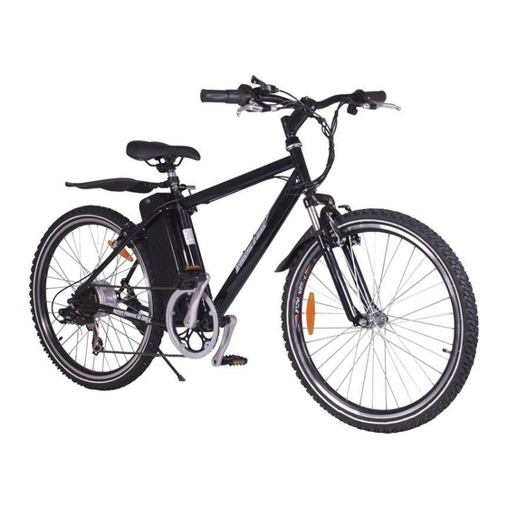
Page 5: Xb-300Sla & Xb-305Sla Electric Bicycle
Warning / important - take notice of this symbol throughout this manual and pay particular attention to the instructions blocked off and preceded by this symbol. TERMINOLOGY POWER Systems – Pedal Assist - A sensor ring and pickup mounted near the bottom bracket allow the bicycle to sense forward pedaling and apply power. -
Page 6: Required Tools
Your new bicycle was partially assembled in the factory and then partially disassembled for shipping. You may have purchased the bicycle already fully assembled and ready to ride OR in the shipping carton in the partially disassembled form. The following instructions will enable you to prepare your bicycle for years of enjoyable cycling. -
Page 7: Before You Ride
BEFORE YOU RIDE ABOUT THIS MANUAL It is important for you to understand your new bicycle. By reading this manual before you go out on your first ride, you’ll know how to get better performance, comfort, and enjoyment from your new bicycle. It is also important that your first ride on your new bicycle is taken in a controlled environment, away from cars, obstacles, and other distractions. - Page 8 Seat Height RIDING POSITION In order to obtain the most comfortable riding position and offer the best possible pedaling efficiency, the seat height should be set correctly in relation to the rider’s leg length. The correct seat height should not allow leg strain from over-extension, and the hips should not rock from side to side when pedaling.
- Page 9 Stem Wedge Bolt Handlebar Adjustment & Height The stem’s “Minimum insertion” mark must not be visible above Handlebar Maximum Height/ Binder Bolt the top of the headset. If the stem is extended beyond this mark, Minimum the stem may break or damage the fork’s steering tube, which Insertion Mark Exceeds 2 1/2”...
-
Page 10: Safety Checklist
SAFETY CHECKLIST Before every ride, it is important to carry out the following safety checks: 1. Brakes • Ensure front and rear brakes work properly. • Ensure brake calipers are not over worn and are correctly adjusted. • Ensure brake control cables are lubricated, correctly adjusted and display no obvious wear. •... -
Page 11: Bicycle Care
• Check that the frame and fork are not bent or broken. • If either is bent or broken, they should be replaced. 9. Accessories • Ensure that all reflectors are properly fitted and not obscured. • Ensure all other fittings on the bike are properly and securely fastened, and functioning. •... -
Page 12: Throttle
THROTTLE TAG (TWIST AND GO) Before you begin riding, turn the main power switch on, then start riding as you would ride any regular, non motor assisted bicycle. After you have begun to ride, slowly twist the throttle (on equipped models) towards you. The more you twist the throttle, the more motor power will be applied to the wheels. -
Page 13: Charger
STORAGE When storing your batteries for a long period of time (longer than two months): • Charge your batteries every 90 days to avoid capacity loss. Batteries slowly self-discharge when left unused for a long period of time; if the battery cells are allowed to reach a critically low voltage, their lifespan and capacity will be permanently reduced. -
Page 14: Bicycle Assembly
**Note: Your bicycle may be equipped with different style components than the ones illustrated within this manual. We recommend that you contact X-Treme if you have doubts or concerns as to your experience or ability to properly assembly, repair, or maintain your bicycle... -
Page 15: Stem And Handlebars
STEM AND HANDLEBARS (STANDARD QUILL-TYPE Remove the protective shipping cap from the stem wedge. Remove the Stem Plug from the stem. Loosen the Stem Bolt with a 6mm allen wrench or 13mm box wrench. Insert the stem into the head tube of the bicycle. Ensure that the Minimum Insertion Line is below the top nut of the headset. - Page 16 WARNING: MINIMUM INSERTION LINE MUST BE HIDDEN WITHIN THE HEADTUBE OF THE BICYCLE. Binder Bolt if the stem is not inserted into the top nut to at least the stem bolt. Stem Bolt NOTE: Some models of bicycles may be equipped with a stem that has an adjustable angle. In addition to the normal assembly, these Top Nut Minimum stems will require angling the stem to the desired position, and securely tightening the 6mm Allen bolt located underneath the stem.
- Page 17 Wedge Head Tube Stem Installation (should be assembled on the bike already) Compression Bolt Handlebar Insert the compression bolt through the top cap and the stem. Begin Top Cap threading into the star nut. Stem Headset Wedge Tighten compression bolt so it removes all play from the fork, but allows Stem Clamp Bolts Bearing Dust Cover the fork to rotate smoothly.
-
Page 18: Forks
Your bicycle is equipped with a Suspension Fork as shown in figure 2 Do not attempt to disassemble a suspension fork yourself. Consult X-Treme Scooters for assistance. If your bike is equipped with a suspension fork, check that the fork compresses and rebounds smoothly. -
Page 19: Seat And Seat Post
Seat Fixing Bolt SEAT AND SEAT POST Seat Clamp Nuts Your bicycle may come equipped with either a standard or a micro-adjustable seat post. Standard seat post Attach the seat to the seat post by first loosening the nuts on the seat clamp. Insert the tapered Quick Release end of the seat post into the seat clamp until it is at the top of the clamp. -
Page 20: Front Wheel
Figure 2 Figure 1 Figure 3 Figure 4 Figure 5 INSTALLING THE FRONT WHEEL Make sure the brakes are loose enough to allow the brake pads easily. Place wheel into fork drop outs (Figure 1). Insert Quick Release Axle (Figure 2) as shown in Figure 3 & 4 with nut. When axle is in place, push lever down on axle to lock into place (Figure 5). -
Page 21: Disc Brakes
DISC BRAKES Check the tightness of the six disc mounting bolts holding the brake rotor onto the wheel. If you need to remove these bolts, be sure to us a thread-locking compound when re-installing them. Make sure the two bolts securing the caliper adaptor bracket to the fork are tight. Thread the brake cable through the caliper as shown and secure it with the cable fixing bolt. -
Page 22: Derailleur Systems
Freewheel DERAILLEUR SYSTEMS Pulley Adjustment The derailleur system includes the font and rear derailleurs, the shift Screw levers, and the derailleur control cables, all of which must function correctly for smooth gear shifting to occur. Guide Pulley DERAILLEUR Although the front and rear derailleurs are initially adjusted at the Adjustment factory, you will need to inspect and readjust both before riding the bicycle Swrews... -
Page 23: Drivetrain
Drivetrain The drivetrain of a bicycle refers to all parts that transmit power to the rear wheel including the pedals, chain, chain wheel, crank set and freewheel. Pedals Pedals are available in a variety of shapes, sizes and materials, and each are designed with a particular purpose in mind. -
Page 24: Troubleshooting
TROUBLESHOOTING PROBLEM POSSIBLE CAUSE REMEDY Low batteries Charge batteries for recommended time Faulty or old batteries Replace batteries Bicycle has reduced range and/or speed Low tire pressure Inflate tires to recommended pressure Brakes dragging against disc Adjust brakes and/or caliper Riding in hilly terrain, headwind, etc. - Page 25 Damaged wires Inspect all wires Charger shows a full charge in an Faulty charger Replace charger Faulty unusually short amount of time batteries Replace batteries Outlet has no power Check outlet for power Indicator light on charger not illuminated Blown fuse (Li-Po4 chargers) Replace fuse when charger is plugged into outlet Faulty charger...
-
Page 26: Specifications
SPECIFICATIONS SPECIFICATIONS Battery: 12V12ah Sealed Lead Acid Battery Battery: 24V/8AH LiPo4 Lithium Battery, 14 cells Frame: Steel Frame: Alloy 6061-T6, TIG welded Front Fork: Alloy suspension front fork Front Fork: Alloy suspension front fork Handlebar: Alloy, with adjustable alloy handlebar stem with scale Handlebar: Alloy, with adjustable alloy handlebar stem with scale Cranks and Chain wheel:... -
Page 27: How To Guide
How To Check Battery Terminals If Battery Not Charging Properly 1.) Remove battery pack from bike 2.) Remove cap from end of battery that has the Four Slots (Key end). 3.) Remove cover plate. 4.) You are now able to look at the Red and Black wires; the Two Black wires should be on the same side as the Key. 5.) If the Black wires are not on the side of the Key carefully open the Terminal Block Cover. -
Page 28: How To Replace Brake Lever
After the cable is secured to the caliper, squeeze the lever several times to see if the brake rubs. At this point in time adjust the brake pads inward or outward depending on if the brake is rubbing or if there is a space between the pad(s) and rotor. (hint: a half turn of adjustment inward of the brake pad can be the difference between having a brake lever that feels spongy to one that is not.) How To Replace Brake Lever 1.) Loosen brake cable at caliper to gain slack in cable. -
Page 29: How To Replace Pedal Shaft
7.) With the wire connector removed from the wires you can now remove the wheel assembly. How To Replace Pedal Shaft (Left & Right is based on sitting on bicycle) Keep parts laid out in order for easier installment. Make yourself a drawing if needed and label each part when removed. -
Page 31: Wiring Diagram
Wiring diagram (Diagram is for representational purpose only. Your bicycle's wiring system may differ) -
Page 32: General Information/Tech Support
DO NOT RETURN TO STORE! IF YOU NEED HELP CALL OR GO ONLINE 1-253-777-0690 www.x-tremescooters.com/support/ For General Information or Parts Visit www.x-tremescooters.com Revised 09-04-13...
Need help?
Do you have a question about the XB-300SLA and is the answer not in the manual?
Questions and answers