
Related Manuals for Gree GWH18AC-D3DNA1B


Summary of Contents for Gree GWH18AC-D3DNA1B
-
Page 1: Service Manual
Service Manual MODEL: GWH18AC-D3DNA1B CB11500430 GWH24AC-D3DNA1B CB11500450 (Refrigerant R410A) GREE ELECTRIC APPLIANCES INC.OF ZHUHAI... -
Page 2: Table Of Contents
Table of Contents Summary and features ..................1 Part 1 Safety Precautions ..................2 Part 2 Specifications .....................3 Part 3 Construction Views ..................5 3.1 Indoor Unit ......................5 3.2 Outdoor Unit ......................6 Part 4 Refrigerant System Diagram ..............7 Part 5 Schematic Diagram ..................8 5.1 Electrical Data......................8 5.2 Electrical Wiring......................8 5.3 Printed Circuit Board....................10... - Page 3 Table of Contents Part 9 Troubleshooting ....................37 9.1 Troubleshooting ....................37 9.2 Diagnostic Charts....................38 9.2.2 Blinking LED of Indoor/Outdoor Unit ..............45 9.2.3 Check Maifunction Process ................49 Part10 Removal Procedure ..................58 10.1 Removal Procedure of Indoor Unit..............58 10.2 Removal Procedure of Outdoor Unit (18K Unit)..........61 10.3 Removal Procedure of Outdoor Unit (24K Unit)..........64...
-
Page 4: Summary And Features
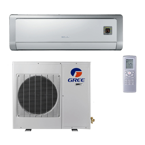
Summary and features Summary and features Indoor Unit GWH18AC-D3DNA1B/I GWH24AC-D3DNA1B/I Outdoor Unit GWH18AC-D3DNA1B/O GWH24AC-D3DNA1B/O Remote Control YT1FF MODE I FEEL TIMER CLOCK TIMER X-FAN TEMP TURBO SLEEP LIGHT... -
Page 5: Part 1 Safety Precautions
1.Safety Precautions Safety Precautions Installing, starting up, and servicing air- -conditioning equipment can be hazardous due to system pressures, electrical components, The unit should be installed according to the instructions and equipment location (roofs, elevated structures, etc.). in order to minimize the risk of damage from earthquakes, Only trained, qualified installers and service mechanics should hurricanes or strong winds. -
Page 6: Part 2 Specifications
Specifications Specifications Model GWH18AC-D3DNA1B GWH24AC-D3DNA1B Product Code CB11500430 CB11500450 Function COOLING HEATING COOLING HEATING Rated Voltage 208-230V~ 208-230V~ Frequency(Hz) 60Hz 60Hz 5275 7325 6155 7620 Total Capacity (W) Standard (Low~High): 1820~6450 1200~7325 2300~7680 1750~8200 18000 25000 26000 21000 Total Capacity (Btu/h) Standard (Low~High):... - Page 7 Specifications Model of Outdoor Unit GWH18AC-D3DNA1B/O GWH24AC-D3DNA1B/O China Resources (Shenyang) Sanyo China Resources (Shenyang) Sanyo Compressor Manufacturer/trademark CO.,LTD CO.,LTD Compressor Model C-6RZ146H1A C-6RZ146H1A Compressor Type Twin rotary compressor Twin rotary compressor L.R.A. (A) Compressor RLA(A) Compressor Power Input(W) 1640 1640...
-
Page 8: Part 3 Construction Views
Constrction views 3. Construction Views 3.1 Indoor Unit Unit:inch Model GWH18AC-D3DNA1B 37-13/16 11-13/16 7-11/16 4-5/8 27-5/16 5-13/16 GWH24AC-D3DNA1B 42-15/16 8-3/16 26-15/16 8-7/16 7-1/2... -
Page 9: Outdoor Unit
Constrction views 3.2 Outdoor Unit GWH18AC-D3DNA1B/O 35-1/16 13-3/8 27-9/16 15-5/8 37-15/16 14-1/2 22-1/16 GWH24AC-D3DNA1B/O 36-1/4 14-9/16 31-1/8 16-13/16 39-3/8 Unit:(inch) 15-11/16... -
Page 10: Part 4 Refrigerant System Diagram
Refrigerant System Diagram 4. Refrigerant System Diagram Heat exchanger 3-Way ( INDOOR ) valve Muffler 2-Way valve 4-Way valve Strainer Expansion valve Heat exchanger Strainer ( OUTDOOR ) Strainer Cooling Heating Refrigerant pipe diameter 18K Unit Liquid : 1/4" (6 mm) Gas : 1/2"... -
Page 11: Part 5 Schematic Diagram
ELECTRONIC EXPANSION VALVE OVERLOAD SAT OVERLOAD BN BROWN COMP COMPRESSOR BLUE BLACK GROUNDING YEGN YELLOW GREEN REACTOR 5.2 Electrical wiring Indoor Unit Models GWH18AC-D3DNA1B/I GWH24AC-D3DNA1B/I DISPLAY TUBE ROOM TEM.SENSOR TEM.SENSOR TUBE ROOM DISP1 DISP2 N(1) COM-OUT AC-L PRINTED CIRCUIT BOARD... - Page 12 Schematic Diagram Outdoor Unit Models GWH18AC-D3DNA1B/O GWH24AC-D3DNA1B/O WARNING Please don't touch any terminal when the voltage of terminal P(DC+) and N(DC-) at AP1 is higher than 30V to prevent the risk 6YEGN COMP of electrical shock! OUTROOM OUTTUBE EXHAUST C(T) TEM.SENSOR...
-
Page 13: Printed Circuit Board
Schematic Diagram 5.3 Printed Circuit Board TOP VIEW No. Port Name Neutral line Neutral line of health function Fuse Live line Power cable of PG motor Live line of health function Jumper cap Link to up-down swing motor Feedback line of PG motor Temperature sensor Display port Port of communication with... - Page 14 Schematic Diagram TOP VIEW Port Name Port Name Port Name Compressor port Compressor overload protector Temperature sensor Electronic expansion valve Fan HALL port Outdoor fan 4-way valve Port of communication with indoor unit Live line Grounding Neutral line Reactor port 1 PFC capacitor port Reactor port 2 BOTTOM VIEW...
-
Page 15: Part 6 Function And Control
6.Function and Control 6.1 Unit Display Panels NOTE: The display panel on the indoor unit can be turned on or off using the remote control . Press the SWING button twice to turn the display on and off. Some of the functions will appear on the display panel, on the remote control, or both. On the Unit: A08297 * The temperature readout will be replaced by an error code if there is a malfunction. -
Page 16: Remote Control Operations
6.3 Remote Control Operations 4. Replace the batteries when there is no audible beep from the CAUTION indoor unit or if the Transmission Indicator fails to light. Set the Clock EQUIPMENT DAMAGE HAZARD Before you start operating the air conditioner, set the clock on the Failure to follow this caution may result in equipment damage. -
Page 17: Remote Control Functions
Remote Control Operation - - Quick Start REMOTE CONTROL FUNCTIONS NOTE: When transmitting a command from the remote control to The remote control is the interface between the user and the the unit, be sure to point the control toward the LED display on the high- -wall systems. -
Page 18: Timer Function
pushed, the louvers will not start moving right away. This is Setting the Room Temperature Set Point due to the fact that the fan will not start running until the coil Pressing the “TEMP +” and “TEMP - -” buttons will raise or lower temperature is warm enough to prevent discomfort to the user the temperature. -
Page 19: Sleep Mode
Timer OFF only Sleep Mode This mode is used to conserve energy and can be used when the unit is in the COOL, HEAT or AUTO mode only. Cool Mode - - Push the SLEEP button. The SLEEP display will appear on the remote control. -
Page 20: Control System
CONTROL SYSTEM The 53GXC(Q) units are equipped with microprocessors in the indoor and outdoor units. They perform the following two functions: 1. Provide safety for the system Stop Compressor 2. Control the system and provide optimum levels of comfort Reduce Comp. Freq. and efficiency. -
Page 21: Cooling Mode
Compressor Over Current Protection MODES OF OPERATION Over current protection can result due to any of the following: The units have five main operating modes: The ambient temperature is too high 1. Fan only 2. Cooling Locked rotor on the compressor 3. -
Page 22: Heating Mode
Heating Mode Cold Blow Prevention This function prevents the cold air from blowing into a space when In this mode, the system heats the room air with the indoor fan in heat mode. When there is a demand for heating one of the running at either the selected speed or on Auto. -
Page 23: Auto Mode
Function and Control AUTO MODE SLEEP MODE When the Auto setting is selected, at startup the unit will run in Additional energy savings can be realized by selecting the Slee cooling, fan only, or heating based on the room temperature at mode. -
Page 24: Part 7 Installation Manual
7.1 Notices for Installation Caution Please contact your Gree authorized service center when the unit is to be relocated. Installation Site Instructions Proper installation site is vital for correct and efficient operation of the unit. Avoid the following sites where: strong heat sources, vapours, flammable gas or volatile liquids are emitted. -
Page 25: Install The Outdoor Unit
Installation Manual Installation Site of Outdoor Unit Install the outdoor unit: 1. Where annoy neighbors. blocking Where it is Where it is dry and the unit is not exposed to direct sunshine or strong wind is installed in accordance with the installation instructions, and is convenient for maintenance and repair. Where the between indoor and outdoor units is within 16ft, and the length of the connecting tubing does not exceed 32ft. -
Page 26: Installation Drawing
Installation Manual 7.2 Installation Drawing Space to the ceiling 5.9 in. Space to the wall Above Above 5.9 in. 5.9 in. Above Space to the wall 118.1 in. Above Air outlet side The dimensions of the space necessary for correct installation of the appliance include the minimum permissible distances to adjacent structures Space to the obstruction... -
Page 27: Installation Guide
INSTALLATION GUIDE 7.3 INDOOR UNIT INSTALLATION INSTALL MOUNTING PLATE 1. Carefully remove the mounting plate, which is attached to the back of the indoor unit. 2. The mounting plate should be located horizontally and level on the wall. All minimum spacings shown in Fig. Fig. -
Page 28: Outdoor Unit Installation
If piping is going through the right or left side: INSTALL ALL POWER AND INTERCONNECTING WIRING TO OUTDOOR UNIT 1. Use a small saw blade to carefully remove the correspond- ing plastic covering on side panel and drill the appropriate size hole where the pipe is going through the wall. - Page 29 Outdoor unit Terminal Block Conduit panel Conduit 115-1-60 Connection Diagram CONNECTING CABLE OUTDOOR TO INDOOR Main Pow er to Indoor Unit Pow er Indoor Pow er Ground Control Ground Control Supply Unit Supply 115-1-60 115-1-60 115-1-60 115-1-60 Outdoor Units 115-1-60 Indoor Units 208/230-1-60 Connection Diagram CONNECTING CABLE OUTDOOR TO INDOOR...
- Page 30 Deep Vacuum Method CAUTION The deep vacuum method requires a vacuum pump capable of pulling a vacuum of 500 microns and a vacuum gage capable of UNIT DAMAGE HAZARD accurately measuring this vacuum depth. The deep vacuum method is the most positive way of assuring a system is free of air and Failure to follow this caution may result in equipment liquid water.
-
Page 31: Start-Up
START- - UP Test Operation Explain Following Items To Customer With The Aid Of The Owner’s Manual: Perform test operation after completing gas leak and electrical safety check. 1. How to turn air conditioner on and off; selecting COOLING, HEATING and other operating modes; setting 1. - Page 33 Exploded Views and Parts List Part Code Description GWH18AC-D3DNA1B/I Product Code CB115N0625_K54715 Front Panel Assy 2001209702 Decorative Strip 20192202D Front Panel 20012027 Filter Assy 11124096 Screw Cover 24252017 Front Case Assy 20012011 Guide Louver 1051409605P Louver 10512097 Louver 10512099 Swing Linkage...
- Page 35 Exploded Views and Parts List Part Code Description GWH24AC-D3DNA1B/I Product Code CB115N0645_K54715 Front Panel Assy 2001211603 Decorative Board 2019221903 Front Panel 20004326 stay bar sub-assy none Filter Sub-assy 11124097 Screw Cover 24252017 Front panel Assy 2001207001 Guide Louver 1051215304P Louver 10512097 Louver 10512099...
- Page 37 Exploded Views and Parts List Part Code Description GWH18AC-D3DNA1B/O Product Code CB115W0431_K54715 Axial Flow Fan 10335008 Fan Motor 15015064 Motor Support Sub-Assy 01705020 Electric box (fireproofing) 01413148 Magnet Coil 4-way Valve 4300040045 4-way Valve Assy 03123245 Rear Grill 01473049 Small Handle...
- Page 39 Exploded Views and Parts List Part Code Description GWH24AC-D3DNA1B/O Product Code CB115W0451_K54715 Condenser Assy 01113446_K54715 Small Handle 26235401 Electric box (fireproofing) 01413426 Left Side Plate 01305043P Chassis Sub-assy 0120377902P Fan Motor 15014034 Axial Flow Fan 10335005 Cabinet 0143500401P Rear Grill 01475013 4-way Valve Assy 03123275...
-
Page 40: Part 9 Troubleshooting
9. T roubleshooting 9.1 Troubleshooting This section provides the required flow charts to troubleshoot problems that may arise. NOTE: Information required in the diagnoses can be found either on the wiring diagrams or in the appendi Required Tools: The following tools are needed when diagnosing the units: S Digital multimeter S Screw drivers (Phillips and straight head) S Needle- -nose pliers... -
Page 41: Diagnostic Charts
9.2 DIAGNOSTIC CHARTS Indoor fan motor Indoor fan motor Indoor fan motor Check motor Check motor Check motor running? running? running? Chart Chart Chart Connect low side gauge at Connect low side gauge at Connect low side gauge at Check for leaks. Check for leaks. - Page 42 DIAGNOSTIC CHARTS (CONT.) Reset circuit breaker. Is Reset circuit breaker. Is Problem fixed Problem fixed Notes: Notes: problem fixed? problem fixed? Before measuring the Volts DC on outdoor TB, Before measuring the Volts DC on outdoor TB, disconnect the field wire on terminal S. disconnect the field wire on terminal S.
- Page 43 DIAGNOSTIC CHARTS (CONT.) Is unit running in outdoor Is unit running in outdoor Beyond operating range Beyond operating range ambient higher than ambient higher than 110 °F? 110 °F? Clean coil. Clean coil. Problem solved Problem solved Outdoor coil clean? Outdoor coil clean? Problem persists? Problem persists?
- Page 44 DIAGNOSTIC CHARTS (CONT.) Check heat sink for Check heat sink for Clean. Clean. obstruction and dirt obstruction and dirt Problem fixed? Problem fixed? Check if connection Check if connection See note below * See note below * is loose is loose Is problem fixed? Is problem fixed? Check voltage and current.
- Page 45 DIAGNOSTIC CHARTS (CONT.) Clean coil. Problem Clean coil. Problem Outdoor coil clean? Outdoor coil clean? Problem solved Problem solved persists? persists? Clean filter. Problem Clean filter. Problem Indoor filter clean? Indoor filter clean? Problem solved Problem solved persists? persists? Check indoor fan Check indoor fan Replace indoor fan Replace indoor fan...
- Page 46 DIAGNOSTIC CHARTS (CONT.) Visually confirm that fan Visually confirm that fan blades and outdoor coil blades and outdoor coil Clear blockage Clear blockage are not blocked. are not blocked. Trace connections from Trace connections from Fix connection Fix connection OD board. Connections OD board.
- Page 47 DIAGNOSTIC CHARTS (CONT.) Check wiring and Check wiring and Fix wiring or Fix wiring or connection between connection between connection connection receiver and ID board. Ok? receiver and ID board. Ok? Check input and output Check input and output Replace receiver board Replace receiver board on ID and receiver on ID and receiver...
-
Page 48: Blinking Led Of Indoor/Outdoor Unit
9.2.2 Blinking LED of Indoor/Outdoor Unit Display of double Display of lamp Name of malfunction eight code Running lamp Cooling lamp Heating lamp Refrigerant system high pressure protection blink 1 time Anti-freezing protection blink 2 times Compressor exhaust high temperature protection blink 4 times AC over-current protection blink 5 times... -
Page 49: Check Maifunction Process
Troubleshooting 9.2.3 Check Malfunction Process Refer to indicator on indoor/outdoor unit and malfunction table (paste on the electric of cover or the top cover of unit) to confirm the malfunction type. The indicator of outdoor controller panel will display the related malfunction; Some malfunctions are to be displayed on the indoor display, while others will be seen on remote controller (press light button 4 times continuously in 3S). - Page 50 Troubleshooting 9.2.3.2 IPM protection, desynchronizing malfunction, phase current of compressor is overcurrent (outdoor unit malfunction) Indoor display: H5 (dual-8 display), heating indicator is off for 3S and blinks 5 times. P5 (dual-8 display), heating indicator is off for 3S and blinks 15 times. H7 (dual-8 display), heating indicator is off for 3S and blinks 7 times.
- Page 51 Troubleshooting 9.2.3.3 Diagnosis of high temperature overload protection (Check outdoor unit when cooling and indoor unit when heating) Indoor unit display: H4 (dual-8 display), heating indicator is off for 3S and blinks 4 times. Main detection points: Is the indoor and outdoor ambient temperature in normal range? Is the indoor and outdoor fan running normally? Is the radiating environment of indoor and outdoor unit OK? Is the indoor and outdoor pipe temperature sensor normal?
- Page 52 Troubleshooting 9.2.3.4 Diagnosis of failure startup (outdoor unit malfunction) Indoor display: LC (dual-8 display), heating indicator is off for 3S and blinks 11 times. Main detection point: Is the compressor wiring correct? Is the off time of compressor enough? Is the compressor damaged? Is the refrigerant charging too much? Malfunction diagnosis process: Energize the unit...
- Page 53 Troubleshooting 9.2.3.5 Diagnosis of compressor synchronism (outdoor unit malfunction) Indoor display: H7 (dual-8 display), heating indicator is off for 3S and blinks 7 times. Main detection point: Is the system pressure over-high? Is the work voltage over-low? Malfunction diagnosis process: Synchronism after Synchronism energize the unit...
- Page 54 Troubleshooting 9.2.3.6 Diagnosis of overload and discharge malfunction (outdoor unit malfunction) Indoor display: H3 (dual-8 display), heating indicator is off for 3S and blinks 3 times. E4 (dual-8 display), operation is off for 3S and blinks 4 times. Main detection point: Is the electron expansion valve connected well? Is the expansion valve damaged? Is there refrigerant leakage? After the unit...
- Page 55 Troubleshooting 9.2.3.7 PFC (correction for power factor) malfunction (outdoor unit malfunction) Indoor display: HC (dual-8 display), heating indicator is off for 3S and blinks 6 times. Main detection point: Check if reactor (L) of outdoor unit and PFC capacity are damaged Malfunction diagnosis process: Start Check the...
- Page 56 Troubleshooting 9.2.3.8 Communication malfunction (outdoor unit malfunction) Indoor display: E6 (dual-8 display), heating indicator is off for 3S and blinks 6 times. Main detection point: Check if the connection wire and the built-in wiring of indoor and outdoor units are connected well and not damaged; Is the communication circuit of indoor mainboard damaged? Is the communication circuit of outdoor mainboard (AP1) damaged? Malfunction diagnosis process:...
- Page 57 Troubleshooting Diagnosis process for outdoor communication circuit: (refer to key test point of outdoor unit): Start Test voltage value with Test 10 position in diagram with voltage meter Number jumping Test voltage value with Test 15 position in diagram with voltage meter Number jumping Outdoor unit...
-
Page 58: Part10 Removal Procedure
Removal Procedure 10. Removal Procedure 10.1 Removal Procedure of Indoor Unit Warning Be sure to wait 10 minutes after turning for a minimum of off all power supplies before disassembling work. panel Remove Push the convex parts the left and right sides panel of the front panel, and then lift the front panel. - Page 59 Removal Procedure water tray Remove earth screw electric box cover Unscrew the ground screw on the electric box cover and loose the clasps to remove electric box cover.Pulll out the wiring terminal.Unscrew the 2 screws fixing the water tray to remove the water tray.
- Page 60 Removal Procedure Unscrew the 2 screws the left of evaporator Turn the evaporator at certain angle to remove it. screws motor and cross-flow louver Remove Unscrew the screws fixing the press plate of motor and connecting motor and cross flow fan to remove the motor and cross flow louver.
-
Page 61: Removal Procedure Of Outdoor Unit (18K Unit)
Removal Procedure 10.2 Removal Procedure of Outdoor Unit (18K Unit) Warning Be sure to wait 10 minutes or more after turning off all power supplies before disassembling work. top cover Remove Twist off the fastening screw used for fixing the handle, pull it downward and then remove the handle. - Page 62 Removal Procedure axial flow blade Remove Loosen the tight nut with spanner and remove the nuts, spring washer, plain washer, then remove the axial flow blade forcibly. clamp nut axial flow blade Remove motor and motor support motor support Twist off the clamping screws, take out the motor, twist off the screws used for fixing the motor support ,pull it upward and then remove the motor support.
- Page 63 Removal Procedure Remove the gas valve and liquid valve liquid valve Twist off the screws used for fixing the gas valve and liquid valve, unsolder the spot weld between gas valve and return-air pipe and then remove the gas bolt valve and liquid valve.
-
Page 64: Removal Procedure Of Outdoor Unit (24K Unit)
Removal Procedure 10.3 Removal Procedure of Outdoor Unit (24K Unit) top cover, front side panel Remove Twist off the clamping screws used for fixing the handle with screwdriver, pull it downward forcibly and then remove the handle. Twist off the screws around the top cover, pull it top cover upward and then remove the top cover. - Page 65 Removal Procedure Remove axial flow blade Loosen the clamp nut with spanner, take out nuts, spring washer, plain washer and then remove the axial flow blade forcibly. clamp nut axial flow blade motor and motor support Remove motor support Twist off the fixing screws and then take out the motor. Twist oft the screws used for fixing the motor support, pull it upward and then remove the motor support.
- Page 66 Removal Procedure Remove the gas valve and liquid valve gas valve bolt Twist off the screws used for the gas valve and liquid valve, unsolder the spot weld between gas valve and return-air pipe and then remove the gas valve and liquid valve.
Need help?
Do you have a question about the GWH18AC-D3DNA1B and is the answer not in the manual?
Questions and answers