Table of Contents
Advertisement
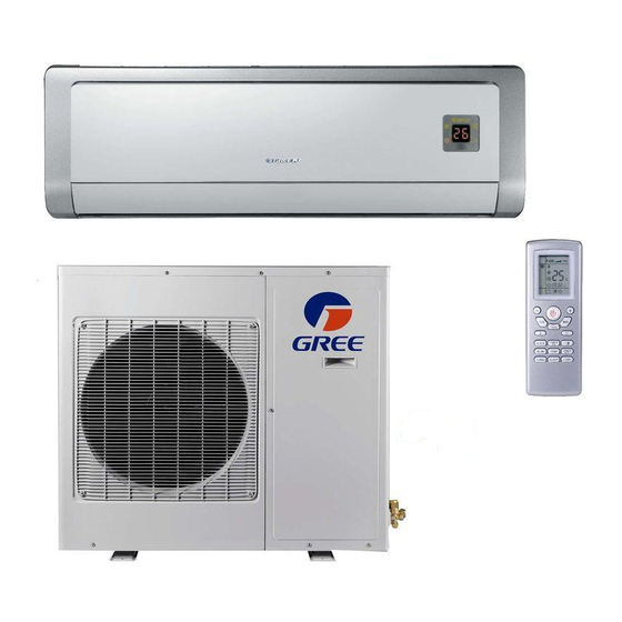
Thank you for selecting GREE evo High Wall
Ductless Air Conditioner and Heating System.
Please read this manual carefully before operation
and keep it for further reference.
For more information, please visit our website at
www.greecooling.com.
HIGH-WALL DUCTLESS
AIR CONDITIONING &
HEATING SYSTEM
Models:
GWH09AB-A3DNA1B
GWH12AB-A3DNA1B
GWH12AB-D3DNA1B
OWNER'S MANUAL
GWH18AB-D3DNA1B
GWH24AB-D3DNA1B
Advertisement
Table of Contents

Related Manuals for Gree GWH09AB-A3DNA1B


Summary of Contents for Gree GWH09AB-A3DNA1B
-
Page 1: Air Conditioning
GWH09AB-A3DNA1B GWH18AB-D3DNA1B GWH12AB-A3DNA1B GWH24AB-D3DNA1B GWH12AB-D3DNA1B Thank you for selecting GREE evo High Wall Ductless Air Conditioner and Heating System. Please read this manual carefully before operation and keep it for further reference. For more information, please visit our website at... -
Page 2: Table Of Contents
Table of Contents Notices for operation..........3 Installation service..........15 Typical operation............5 Installation dimension diagram......16 Identifying major components.........6 Installing the indoor unit........17 Wireless remote control operation......7 Installing the outdoor unit........19 Emergency operation..........10 After installation and testing........20 Cleaning and caring for your unit......11 Circuit diagrams............20 Troubleshooting............12 Warranty..............22... -
Page 3: Notices For Operation
NOTICES FOR OPERATION IMPORTANT OPERATING INFORMATION PLEASE READ CAREFULLY BEFORE OPERATING THE UNIT. WARNING WARNING WARNING Disconnect unit from power source Do not splice the power cord or use If you smell or see smoke, turn unit off when it will not be in use for long an extension cord. - Page 4 NOTICES FOR OPERATION IMPORTANT OPERATING INFORMATION PLEASE READ CAREFULLY BEFORE OPERATING THE UNIT. NOTE NOTE Adjust vertical or lateral airfl ow using the Do not block air intake or outlet vents on remote control. either indoor or outdoor components. Doing so may cause a malfunction of the unit.
-
Page 5: Typical Operation
TYPICAL OPERATION How your EVO unit works in heating How your EVO unit works in cooling In cooling mode, your EVO indoor unit will absorb heat from In heating mode, your EVO outdoor unit will absorb heat the room, then the EVO outdoor unit will discharge the heat from the outdoor ambient, then the EVO indoor unit will to the outdoors. -
Page 6: Identifying Major Components
IDENTIFYING MAJOR COMPONENTS Indoor unit Air in Remote receiver sensor Front panel Filter Discharge Swing louvers Remote control Outdoor unit Air in Refrigerate lines and control wires Condesate drainage pipe Discharge... -
Page 7: Wireless Remote Control Operation
WIRELESS REMOTE CONTROL OPERATION Names and Functions of Remote Control Buttons Signal Transmitter SLEEP button Press this button to select SLEEP ON or SLEEP OFF. This function must be set after the unit is powered on. It will not function under AUTO or FAN modes. FAN button Select Low, Medium or High in Auto mode for default fan speed. - Page 8 WIRELESS REMOTE CONTROL OPERATION Names and Functions of Remote Control Buttons NOTE: Not every unit has each of the functions described below. If your unit does not come equipped with a certain function, the button will be inactive. SWING UP and DOWN BUTTON Use this function to control direction of air circulation.
- Page 9 WIRELESS REMOTE CONTROL OPERATION Getting Started: 1. When the unit is powered on, press ON/OFF button to start unit. (NOTE: When unit is powered on, the guide louver of the main unit will close automatically.) 2. Press MODE button and select desired running mode. 3.
-
Page 10: Emergency Operation
WIRELESS REMOTE EMERGENCY OPERATION CONTROL OPERATION If the wireless remote control unit is lost or damaged, use THE MANUAL OVERRIDE SWITCH to operate the unit. Manual operation means the unit is operating in AUTO Replacing Batteries mode. In AUTO mode, the system will automatically maintain a room temperature between 64°F (17.8°C) 1. -
Page 11: Cleaning And Caring For Your Unit
CLEANING AND CARING FOR YOUR UNIT CAUTION • Turn off power and disconnect unit from power source before cleaning. Failure to do so could cause electric shock. • Never spray water on either indoor or outdoor unit. This could cause damage or unit failure. •... -
Page 12: Troubleshooting
TROUBLESHOOTING WARNING Do not attempt any repairs on the unit yourself. Incorrect repair can cause shock or fi re. Always call a qualifi ed service professional. Using these Troubleshooting suggestions can save time when you contact the qualifi ed service professional. CAUSE/SOLUTION PROBLEM Air conditioner does not restart. - Page 13 TROUBLESHOOTING CAUSE/SOLUTION PROBLEM The unit will not run. Cause: There are a number of situations that will prevent the system from running. Solution: Check for the following: • Circuit Breaker is “tripped or turned Off”. • Power Button of remote is not turned ON. •...
- Page 14 TROUBLESHOOTING CAUSE/SOLUTION PROBLEM The unit will not deliver air. Cause: There are a number of system functions that will prevent the indoor fan from running. Solution: Check for the following: • In heating Mode, the indoor fan may not start for 3 minutes if the room temperature is very low to prevent blowing cold air.
-
Page 15: Installation Service
INSTALLATION SERVICE Important Information About Important Safety Considerations Installation 1. Use only rated voltage installation and a dedicated circuit. Installation must be performed by qualifi ed service 2. Power source must be grounded. Connection to circuit professional according to codes and information in this breaker box must allow for power surge or excessive manual. -
Page 16: Installation Dimension Diagram
INSTALLATION DIMENSION DIAGRAM Rear Panel 6 in. (15cm) Space to the ceiling Above 6 in. Space to the wall (15cm) Above 6 in. (15cm) Above Space to the wall 72 in. 118¹⁄₈ in. (183 cm) (300 cm) Above Above Space to the floor Air outlet side Air inlet side Space to the obstruction... -
Page 17: Installing The Indoor Unit
INSTALLING THE INDOOR UNIT Installing the Rear Panel Connecting Indoor and Outdoor Electrical Wiring 1. First fi nd the center of the indoor unit in relation to the rear panel before mounting to the wall. If rear panel is 1. All wiring should follow the enclosed wiring diagrams. not attached to the indoor unit, place the rear panel on 2. -
Page 18: Install The Indoor Unit
INSTALLING THE INDOOR UNIT Install the Indoor Unit Install the Refrigerant Pipes Piping may lead out from right, right rear, left or left rear. 1. Align the center of the piping fl are with appropriate valve. 1. When installing piping and wiring from left or right side, cut off the tailings from the chassis. -
Page 19: Installing The Outdoor Unit
INSTALLING THE OUTDOOR UNIT Electrical Wiring Check for Leaks 1. Disassemble handle on front or right-hand side plate of Use soapy water or leak detector to verify joints, outdoor unit. connections and couplings are not leaking. 2. Remove wire clamp. Connect power connection cable to line bank. -
Page 20: After Installation And Testing
AFTER INSTALLATION AND TESTING USE THIS CHECKLIST TO VERIFY PROPER INSTALLATION: ITEM TO BE CHECKED POSSIBLE MALFUNCTION Unit is fi rmly installed. Unit may shake or emit noise. Leak test has been performed. Unit will not heat or cool effi ciently. Suffi... - Page 21 CIRCUIT DIAGRAMS Outdoor Unit For 230V heat pump models: For 230V cool only models: 63633065 63 633063 For 115V heat pump models: For 115V cool only models: 6 3 6 3 3 0 8 3 6 3633084...
-
Page 22: Warranty
Installing Contractor: Address / Phone No.: GREE Distributor (hereinafter “Company”) warrants this product against failure due to defect in materials or workmanship under normal use and maintenance as follows. All warranty periods begin on the date of original purchase from wholesaler/ supplier. - Page 23 THIS WARRANTY DOES NOT COVER: Labor or other costs incurred for diagnosing, repairing, removing, installing, shipping, servicing or handling of either defective parts, or replacement parts, or new units. Normal maintenance as outlined in the installation and servicing instructions or Owner’s Manual, including filter cleaning and/or replacement and lubrication.
- Page 24 ©GREE 66162632 V2.0 GREE ELECTRIC APPLIANCES, INC. OF ZHUHAI www.greecooling.com...
Need help?
Do you have a question about the GWH09AB-A3DNA1B and is the answer not in the manual?
Questions and answers