Table of Contents
Advertisement
Quick Links
Advertisement
Table of Contents
Troubleshooting

Related Manuals for NTI SM-nXm-AV-LCD


Summary of Contents for NTI SM-nXm-AV-LCD
- Page 1 NETWORK 1275 Danner Dr Tel:330-562-7070 TECHNOLOGIES Aurora, OH 44202 Fax:330-562-1999 INCORPORATED www.networktechinc.com ® VEEMUX Series SM-nXm-AV-LCD Audio/Video Matrix Switch Installation and Operation Manual MAN069 Rev Date 2/5/2014...
- Page 2 TRADEMARK VEEMUX is a registered trademark of Network Technologies Inc in the U.S. and other countries. COPYRIGHT Copyright © 2002, 2014 by Network Technologies Inc. All rights reserved. No part of this publication may be reproduced, stored in a retrieval system, or transmitted, in any form or by any means, electronic, mechanical, photocopying, recording, or otherwise, without the prior written consent of Network Technologies Inc, 1275 Danner Drive, Aurora, Ohio 44202.
-
Page 3: Table Of Contents
TABLE OF CONTENTS Introduction..................................1 Basic Operation ................................1 Supported Web Browsers............................1 Ordering Information..............................1 Optional Features ..............................1 Materials ..................................2 Cables..................................2 Default User Name and Passwords ..........................2 Features and Functions..............................3 Installation..................................4 Connect the Sources ..............................4 Connect the Monitors and Speakers ........................... - Page 4 Video Switch Page .............................. 23 Audio Switch Page .............................. 25 Setup Pages ................................ 26 User Management ..............................27 Add User................................27 Edit User ................................28 Input Names ................................ 29 Output Names..............................29 Outputs Scanning Sequences ..........................30 Update Firmware ..............................32 Change Password Page............................
- Page 5 Figure 21- Web interface Password page............................33 Figure 22- Updating the Web Server ............................... 33 Figure 23- Web interface Logout page............................. 34 Figure 24- Device Discovery Tool..............................35...
-
Page 6: Introduction
The VEEMUX-A Audio/Video Matrix switch is built to a specific size ranging from 8 to 32 inputs and 2, 4, 8, 12, or 16 outputs. Simply order an SM-nXm-AV-LCD where the “n” in the part number represents the number of inputs and the “m” in the part number represents the number of outputs. -
Page 7: Materials
All cables are sold separately. The following table lists the available stocked cables with their length in feet. All of the 15HD and BNC input and output connectors on VEEMUX-A are female. Custom cables are available – contact NTI for pricing and distance / resolution limitations. -
Page 8: Features And Functions
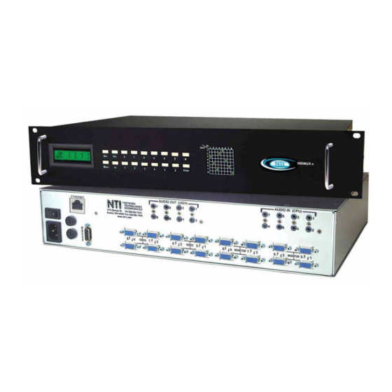
NTI VEEMUX AUDIO/VIDEO MATRIX SWITCH Front View of VEEMUX-A 1 2 3 4 6 7 8 VEEMUX Network Tech nologies Inc MENU ENTER Rear View of VEEMUX-A AUDIO OUT (USER) AUDIO IN (CPU) ETHERNET NETWORK TECHNOLOGIES INCORPORATED 1275 Danner Dr... -
Page 9: Installation
NTI VEEMUX AUDIO/VIDEO MATRIX SWITCH INSTALLATION Connect the Sources Turn OFF power to all video sources (inputs) that will be connected to the VEEMUX-A before connecting or disconnecting any cables. For each video source, connect a VEXT-xx-MM cable from the video port of the source to a video input ("VIDEO 1") of the VEEMUX-A (see Fig. -
Page 10: Connect The Monitors And Speakers
NTI VEEMUX AUDIO/VIDEO MATRIX SWITCH Connect the Monitors and Speakers Connect a video output device to the port labeled MONITOR 1 on the rear of the VEEMUX-A (see Fig. 2). Repeat step 6 for remaining output devices (monitors). Connect audio output device (speakers) to port labeled AUDIO OUT 1. -
Page 11: Connect To The Ethernet
NTI VEEMUX AUDIO/VIDEO MATRIX SWITCH Connect to the Ethernet If the Telnet Interface (page 14) or Web Interface (page 22) will be used, an Ethernet connection to the Local Area Network (LAN) must be made using Cat5 cable with RJ45 connectors attached. -
Page 12: Control Options
(see page 36 – Infrared Control). With the RS232 or WEB Interface options, there are no external devices to be purchased. NTI provides software commands as well as a test program to ensure the RS232 functions properly (see page 10 –... -
Page 13: Volume Control
NTI VEEMUX AUDIO/VIDEO MATRIX SWITCH • Connecting audio only To make an audio connection without changing the current video connection, use any of the following commands: <OUT>, < ▼ >, < ▼ >, Single digit output port number, <IN> or <ENTER>, Single digit input port number, <ENTER>. -
Page 14: Menu Button
NTI VEEMUX AUDIO/VIDEO MATRIX SWITCH Menu Button The Menu button is used to configure the RS-232 port. • The baud rate is selected from the “Baud Rate Menu.” To access this menu, use the command: <MENU>, the <1> key Next, press the keypad number corresponding with the desired baud rate: <1>... -
Page 15: Rs232 Control
TXD and RXD are the only active signals. A straight through DB-9 cable (not null modem) will work for most CPUs. To daisy chain multiple units, use NTI Matrix-Y-1 "Y" cables, except for the last unit connected. (see Fig 6). For a pinout of the Matrix-Y-1 cable, see page 45. -
Page 16: Command Protocol
NTI VEEMUX AUDIO/VIDEO MATRIX SWITCH Command Protocol CPU controller commands supported by the unit are defined below. All commands must be terminated with a <CR> (carriage return). When a command is sent, the entire string is echoed back along with a response from the addressed unit as shown in the Command Definitions table (below). -
Page 17: Autostatus
NTI VEEMUX AUDIO/VIDEO MATRIX SWITCH Command Definitions (Cont’d) Command String Good Response Description RT SW * <CR>timeout<CR> Read the website timeout; timeout = numeric string of timeout in seconds. Values: 60, 300, 600, 900, 1800, 3600, 7200, 18000, 28800 SS SW,00 *<CR>... -
Page 18: Matrix Switcher's Control Program For Windows 9X, Nt, 2000, Xp, Vista And 7
The Matrix Switcher’s Control Program performs best on monitors set to a screen resolution of at least 800 X 600. Instruction for using the Matrix Switcher’s Control Program is available by opening "MSCP Help" in the "NTI" program group once the program has been installed and is open on the screen. -
Page 19: Ethernet Operations
NTI VEEMUX AUDIO/VIDEO MATRIX SWITCH Ethernet Operations Selection Description Set Unit IP Address - enter the desired IP address in xxx.xxx.xxx.xxx format - number of digits is minimum 1 and maximum 3 for each field. Leading zeroes are accepted Set Unit Subnet Mask - enter the desired IP address in xxx.xxx.xxx.xxx format... - Page 20 NTI VEEMUX AUDIO/VIDEO MATRIX SWITCH The following commands are now available: Command Reply Description H(elp) or Displays the list of commands Help h(elp) CS nn,mm *<CR> Connect One Output nn To Input mm CA nn *<CR> Connect All Outputs To Input nn Read Connection For Output.
-
Page 21: Telnet Interface-Port 2005
NTI VEEMUX AUDIO/VIDEO MATRIX SWITCH Telnet Interface-Port 2005 For a software control type of telnet interface session (versus operator telnet control through port 2000 as described on page 14), connect to the VEEMUX through the current IP address at port 2005. To do this, a connection to port 2005 must first be enabled (see Web Setup on page 26). -
Page 22: Command Detail
NTI VEEMUX AUDIO/VIDEO MATRIX SWITCH Command Detail RU-Read Unit Size Command: Byte 1 Byte2 Byte3 ‘R’ ‘U’ <CR> (0x52) (0x55) (0x0D) Response: Byte 1 Byte 2 Byte 3 Byte 4 Byte 5 Byte 6 Byte 7 Byte 8 Byte 9 ‘r’... -
Page 23: Ss_01- Enable Auto Status Mode
NTI VEEMUX AUDIO/VIDEO MATRIX SWITCH SS_01- Enable Auto Status Mode Command: Byte 1 Byte 2 Byte 3 Byte 4 Byte 5 Byte 6 ‘S’ ‘S’ Space ‘0’ ‘1’ <CR> (0x53) (0x53) (0x20) (0x30) (0x31) (0x0D) Response: Byte 1 Byte 2 <CR>... -
Page 24: Ao-Read Audio Connection For Output Port
NTI VEEMUX AUDIO/VIDEO MATRIX SWITCH AO-Read Audio Connection for Output Port Command: Byte 1 Byte 2 Byte 3 Byte 4 Byte 5 Byte 6 ‘A’ ‘O’ Space Output – first digit Output – second digit <CR> (0x41) (0x4F) (0x20) (0x30…0x32) (0x30…0x39) -
Page 25: Av- Set Audio Volume For Output Port
NTI VEEMUX AUDIO/VIDEO MATRIX SWITCH AV- Set Audio Volume for Output Port Command: Byte 1 Byte 2 Byte 3 Byte 4 Byte 5 Byte 6 Byte 7 Byte 8 Byte 9 ‘A’ ‘V’ Space Output – 1st digit Output – 2nd digit ‘,’... -
Page 26: Ar- Read Mute And Volume For Audio Output Port
NTI VEEMUX AUDIO/VIDEO MATRIX SWITCH AR- Read Mute and Volume for Audio Output Port Command: Byte 1 Byte 2 Byte 3 Byte 4 Byte 5 Byte 6 ‘A’ ‘R’ Space Output – first digit Output – second digit <CR> (0x41) -
Page 27: Web Interface
To open a SSL-encrypted connection, type: Address https://192.168.1.30 You will be prompted to accept a certificate. Accept the NTI certificate. A "Welcome Page" will appear. Figure 7- Web interface Welcome page Enter the Password Click on a link to the left to be prompted for a username and password. -
Page 28: Main Menu
NTI VEEMUX AUDIO/VIDEO MATRIX SWITCH Main Menu The VEEMUX main menu provides control over all functions of the switch. The administrative menu includes options not available to other users with limited privileges. When logged in as a user other than the Administrator, only the VIDEO SWITCH, AUDIO SWITCH, CHANGE PASSWORD, HELP, and LOGOUT options will be available. - Page 29 NTI VEEMUX AUDIO/VIDEO MATRIX SWITCH Note: If changes are made using the keypad (page 7) or by another user through the web interface, you must refresh the screen using your browser to see those changes. Note: Configuration 0 will be automatically loaded when the VEEMUX-A is powered up.
-
Page 30: Audio Switch Page
NTI VEEMUX AUDIO/VIDEO MATRIX SWITCH Audio Switch Page To change audio connections only, the Audio Switch page (right) enables the user to control the audio connections independently of the video connections. Note: If Scan Mode is enabled for the output port being connected to, changes to that output port connection will not be accepted. -
Page 31: Setup Pages
NTI VEEMUX AUDIO/VIDEO MATRIX SWITCH Setup Pages These settings enable the user to configure the VEEMUX-A web interface connection. This change will take a few seconds and automatically redirect the user to the IP address specified. Note: Since the webserver will be restarting all active connections will be logged out. -
Page 32: User Management
NTI VEEMUX AUDIO/VIDEO MATRIX SWITCH User Management The Administrator can assign usernames and passwords to up to 14 users. Once assigned, the Administrator can control which ports a user will have access to. Under the ADMINISTRATION menu, select “USER MANAGEMENT”. -
Page 33: Edit User
NTI VEEMUX AUDIO/VIDEO MATRIX SWITCH Edit User To Edit a User, select “EDIT USER” from the USER MANAGEMENT section of the menu. Figure 16- Edit User settings From the Edit User page, the Administrator can change all user settings or delete the user altogether. -
Page 34: Input Names
NTI VEEMUX AUDIO/VIDEO MATRIX SWITCH Input Names The Input Names pages (Video and Audio) enable the Administrator to change the names of the video and audio input ports displayed on the Switch page. To change an input port name, enter the name of the port for the desired input port number, and press "Save". -
Page 35: Outputs Scanning Sequences
NTI VEEMUX AUDIO/VIDEO MATRIX SWITCH Outputs Scanning Sequences Figure 19- Outputs Scanning Sequences page The Outputs Scanning Sequences page (accessible only to the Administrator) displays the configuration of an automatic switching sequence from input (video source) to input for each output (monitor). - Page 36 NTI VEEMUX AUDIO/VIDEO MATRIX SWITCH Example of using Outputs Scanning Sequences Problem: A synchronous scan is desired for all outputs with a dwell time of 30 minutes per input, and no two outputs should be looking at the same input at any given time.
-
Page 37: Update Firmware
2. Repeat the update process from the first step 2 above. 3. If you get another Fatal Error message, call NTI tech-support at 1-800-742-8324 or 330-562-7070. FYI: The VEEMUX-A should continue to run normally unless it is reset. However, damage may have occurred... -
Page 38: Change Password Page
NTI VEEMUX AUDIO/VIDEO MATRIX SWITCH Change Password Page Figure 21- Web interface Password page Use this page to change the password for accessing the web interface. (This password is also used for the telnet interface.) Be sure to make note of the new password exactly as it is case sensitive. The password must be between 5 and 16 characters in length and can be alphabetical or numeric. -
Page 39: Logout Page
NTI VEEMUX AUDIO/VIDEO MATRIX SWITCH Logout Page Figure 23- Web interface Logout page This page will enable the user to end the session and close the web interface connection. Click on the "Press Here to Continue Logout" button to exit the VEEMUX-A web interface. -
Page 40: Device Discovery Tool
DEVICE DISCOVERY TOOL In order to easily locate NTI Devices on a network, the NTI Device Discovery Tool may be used. A link to the Discovery Tool is provided on the web page that appears when you insert the instruction manual CD provided into your CD ROM drive. Either click on the link or browse the CD to locate the NTIDiscover.jar file. -
Page 41: Infrared Control
(Optional) The IRT-64X32 (or IRT) is an infrared remote transmitter that enables the user to control up to four (4) NTI VEEMUX Audio/Video Matrix switches via an infrared receiver from up to 50 feet away (with an unobstructed view). The IRT is battery-powered and always ready to use. -
Page 42: How To Use The Irt
The IRT-64X32 enables the user to control the connections of up to 32 input ports and 16 output ports on up to four (4) separate NTI audio/video matrix switches. When any key is pressed, the IRT will power ON. A number key should always be pressed first unless a change to the configuration is desired (see "Set Configuration"... -
Page 43: Change Output Port
NTI VEEMUX AUDIO/VIDEO MATRIX SWITCH Change Output Port Press the desired port number. If there is no change in the desired output port, the output port must still be selected. As the digits are selected, the last number entered will blink. -
Page 44: Set Configuration
NTI VEEMUX AUDIO/VIDEO MATRIX SWITCH Set Configuration The IRT-64x32 factory default setting is 32 inputs and 16 outputs. When the batteries are changed the setting will return to the default value. At the default setting the IRT has the ability control any matrix switch with up to 32 inputs and 16 outputs without changing the configuration. -
Page 45: Battery Replacement
Reset the configuration if a range other than the default setting is desired. Specifications • 50 feet maximum operating range between the transmitter and the front of the NTI switch / infrared receiver. Note: Line of sight between IRT and receiver must be unobstructed. •... -
Page 46: Ddc Support
NTI VEEMUX AUDIO/VIDEO MATRIX SWITCH DDC SUPPORT (Optional) DDC information allows the CPU to automatically select the optimal resolution for the monitor by receiving, at power up, information from the monitor concerning its resolution specifications. When DDC Support is installed, the DDC information is acquired from the monitor by the VEEMUX-A switch when the VEEMUX-A is powered-up. -
Page 47: Rs232 Upgrade Of The Front Panel Lcd Firmware
VEEMUX-A. To prepare, first download the rmtlcd_va_1_x. hex file (x= the current firmware version) from the NTI Video Matrix Switch website http://www.networktechinc.com/vmtx.html. The following will be needed: 1 PC running HyperTerminal (or other terminal program) equipped with a 9 pin or 25 pin serial port A VEEMUX-A made to use the Firmware Upgrade feature 1 serial cable wired straight through to connect your PC's serial port to the “RS232”... - Page 48 NTI VEEMUX AUDIO/VIDEO MATRIX SWITCH Press <L> to load the firmware (hex) file. This will prepare the file for transfer to the VEEMUX-A. If the file fails to load, press the <C> key to clear the old firmware, and press <L> to load it again.
-
Page 49: Rs232 Connection Cables
NTI VEEMUX AUDIO/VIDEO MATRIX SWITCH RS232 CONNECTION CABLES Pinout of RS232 port on VEEMUX-A The VEEMUX-A RS232 serial port is a DB-9F (female) connector configured as a DCE (data communication equipment) port. The RS232 port interface signals are listed below, including equivalent CCITT V.24 identification, and signal direction:... -
Page 50: Pinout For Matrix-Y-1 Cable
This NTI switch was designed to be directly mounted to a rack. It includes a mounting flange to make attachment easy. Install 4 cage nuts (supplied) to the rack in locations that line up with the holes (or slots) in the mounting flange on the NTI switch. -
Page 51: Specifications
NTI VEEMUX AUDIO/VIDEO MATRIX SWITCH SPECIFICATIONS DESCRIPTION SPECIFICATION Operating temperature -18°C - 55°C (0°F - 131°F) (17-90% non-condensing RH) Storage temperature -30°C - 60°C (-20°F-140°F) (17-90% non-condensing RH) Power requirements 110 or 220VAC @ 50 or 60Hz Fuse protection 2A 240VAC Fast-blo... -
Page 52: Troubleshooting
Servicing NTI products are not intended to be serviced in the field and contain no user-serviceable parts. In the event repair is needed, all servicing must be performed by factory trained and authorized service personnel. -
Page 53: Warranty Information
NTI VEEMUX AUDIO/VIDEO MATRIX SWITCH WARRANTY INFORMATION The warranty period on this product (parts and labor) is two (2) years from the date of purchase. Please contact Network Technologies Inc at (800) 742-8324 (800-RGB-TECH) or (330) 562-7070 or visit our website at http://www.networktechinc.com...
Need help?
Do you have a question about the SM-nXm-AV-LCD and is the answer not in the manual?
Questions and answers