Table of Contents
Advertisement
Quick Links
NTI
NTI
NETWORK
TECHNOLOGIES
INCORPORATED
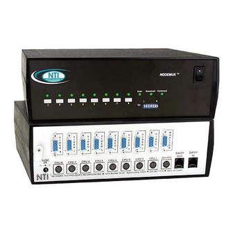
ST-x U ( U n i v e r s a l K V M S w i t c h )
I N S T A L L A T I O N / U S E R G U I D E
M A N 0 6 4
R e v D a t e 1 1 / 2 3 / 2 0 0 1
PS/2
Macintosh
SUN WORKSTATION
PS/2
1275 Danner Dr
Tel:330-562-7070
Fax:330-562-1999
Aurora, OH 44202
VGA
Multi-Scan
Monitor
PC, SUN, or MAC Keyboard / Mouse
ST-8U
NTI
NETWORK
TECHNOLOGIES
INCORPORATED
2
3
4
5
6
7
1
MODE
BROAD
COM
SCAN
CAST
MAND
1 2 3 4 5 6 7 8
ON
OFF
REMOTE REMOTE
8
OUT
IN
PS/2
Macintosh
SUN WORKSTATION
PS/2
Advertisement
Table of Contents

Related Manuals for NTI ST-8U-R


Summary of Contents for NTI ST-8U-R
- Page 1 NETWORK 1275 Danner Dr Tel:330-562-7070 TECHNOLOGIES Fax:330-562-1999 Aurora, OH 44202 INCORPORATED ST-x U ( U n i v e r s a l K V M S w i t c h ) I N S T A L L A T I O N / U S E R G U I D E M A N 0 6 4 R e v D a t e 1 1 / 2 3 / 2 0 0 1 Multi-Scan...
-
Page 2: Table Of Contents
T A B L E O F C O N T E N T S ........................................1 I N T R O D U C T I O N ...........................................2 M A T E R I A L S ...................................2 Materials Supplied with this kit: REQUIRED ..............................2 Materials... -
Page 3: I N T R O D U C T I O N
RS232 (Control the system from the serial port of any host computer with an RS232 port.)(Model ST-x U - R S ) S P E C I A L N O T E : In order to use models ST-8U-R, ST-8U-RO, ST-4U-R, and ST-4U-RO in conjunction with a wired remote control, they must be connected as slaves, daisy-chained in a cascaded system (See CASCADING on page 7). -
Page 4: M A T E R I A L S
M A T E R I A L S Materials Supplied with this kit: N T I U N I V E R S A L K V M S w i t c h REQUIRED Materials Supplied, but A set of 2 cables for each computer being connected to the switch: PS/2 computer to Switch V E X T - x x - M M f o r video interface V K T I N T - x x - M M f o r k e y b o a r d a n d m o u s e interface... -
Page 5: I N S T A L L A T I O N
I N S T A L L A T I O N Turn OFF power to all computers that will be connected to the NTI Switch before connecting or disconnecting any cables to or from them. W A R N I N G... - Page 6 Connect the keyboard to the port labeled KEYBD on the rear of the NTI Switch following one of the methods detailed below: A. If using a PS/2 keyboard, attach the 8-pin male end of a VKTINT-1 to the NTI switch at the KEYBD port.
- Page 7 (See Fig. 8-10 below.) b. Connect the appropriate NTI video cable (see the chart below) from the video port of the computer to the video port of the NTI Universal KVM switch (VIDEO PC-x) with the same port number as the keyboard (see Fig. 8-10 b e l o w ) .
- Page 8 W A R N I N G ! If a serial mouse port is being used on a PC to connect a serial host to an NTI switch, do not use a generic 9D-to- 6mD adapter (Fig. 11) to make connection to the PS/2 cable-- use a VOPEX-IM9D (Fig. 12) to convert the signal from the serial port to PS/2.
-
Page 9: Limitations
- that is, slaves can only have CPUs of the same platform connected to them and the cable between the slave and master unit must support that platform. In order to use models ST-8U-R, ST-8U-RO, ST-4U-R, and ST-4U-RO in conjunction with a wired remote control, they must be connected as slaves, daisy-chained in a cascaded system. -
Page 10: Cascaded Installation
Note: For slave models ST-8U-R, ST-8U-RO, ST-4U-R, and ST-4U-RO the extension cable will connect to the “DAISY IN” a n d “ D A I S Y O U T ” p o r t s r a t h e r t h a n “ R E M O T E I N ” a n d “ R E M O T E O U T ” . -
Page 11: Configuration Of Dip-Switches 1-6
U S I N G T H E N T I U N I V E R S A L K V M S W I T C H Control over the computers attached to the NTI Universal KVM switch is achieved through operation of the Universal KVM switch. -
Page 12: M O D E S O F O P E R A T I O N
K E Y B O A R D C O N T R O L • • Keyboard control of the Universal KVM switch can be achieved through either B a s i c C o m m a n d M o d e , o r O S D Command Mode (OSD is purchased as a separate option). -
Page 13: S C A N M O D E
NOTE: The “port” mentioned in the Command Functions on page 10 refers to the combination of the video (VIDEO PC-x) and k e y b o a r d ( K E Y - x ) of like numbers that a computer is connected to (i.e. the computer that is connected to VIDEO PC-1 and KEY-1 will be identified as PORT 1 or P01). -
Page 14: U S I N G T H E S E C U R I T Y F E A T U R E
Once logged-in, follow the instructions on page 13 for setting up users and changing the password. Once the password is setup, if it is lost or forgotten, the administrator will have to contact NTI for assistance on clearing the password and set it up again. -
Page 15: A D M I N I S T R A T I O N M O D E
A D D I T I O N A L M O D E S A V A I L A B L E W I T H S E C U R I T Y : The three modes that follow are only available if the administrator is logged in. A D M I N I S T R A T I O N M O D E Administration Mode allows the administrator to use the following functions: Function:... -
Page 16: O P T I O N A L O S D C O N T R O L
I N T R O D U C T I O N The NTI optional On Screen Display (OSD) allows a user to name the computers connected to the Universal KVM switch and connect to them using that name from a single keyboard and mouse. The OSD is positioned on the user's monitor, displaying 8 computer names at a time. -
Page 17: S C A N M O D E
C O M M A N D M O D E ( Cont’d) Function: Keystroke: Selects the last port on the switch Enters Search Mode and adds a character (Type any alphabetical or numeric character) to search string and selects the CPU’s name that matches best. -
Page 18: E D I T M O D E
E D I T M O D E Edit Mode allows the user to modify the names of the CPUs connected to the switch. Names of CPUs can be up to 12 characters in length. When in Edit Mode, multiple keystroke combinations are not valid (<SHIFT>+P, <CTRL>+P, <ALT>+ P, and P will all type a “P”... -
Page 19: M A I N T E N A N C E M O D E
S e a r c h M o d e (Cont’d) Function: Keystroke: Add a character to the search (Type any alphabetical or numeric character) string and select the best matching CPU name Exit Search Mode, return to C o m m a n d M o d e Enter Switch to selected port M A I N T E N A N C E M O D E... -
Page 20: H E L P M O D E
K e y b o a r d M a p p i n g The keyboard configuration of each computer is saved in the NTI Universal KVM Switch. For example, if the computer attached to Port 4 had CAPS LOCK and NUM LOCK selected the last time that computer was accessed, then they will automatically be set... -
Page 21: K E Y B O A R D - T O - C O M P U T E R T R A N S L A T I O N
K E Y B O A R D - T O - C O M P U T E R T R A N S L A T I O N The NTI Universal KVM switch enables the mixture of otherwise incompatible peripheral computer components with each other by performing keyboard-to-computer translations automatically (i.e. - Page 22 If the unit is in a plastic case, the digital board is located on the bottom of the case, requiring the user to partially disassemble the unit to gain access to the jumpers block. If the unit has the OSD option (ST-x U - O ) , the procedure will be different than if the unit does not have the OSD option.
- Page 23 To avoid further more difficult disassembly, the video board and front panel will be removed from the ST-x U a s a n a s s e m b l y . Carefully loosen the video board from the standoffs. With it loosened, grasp firmly the video board and front panel at the same time and slide the front panel up out of the slots in the plastic case that support it.
- Page 24 NOTE: Before proceeding, it is important to discharge any static charge you may be carrying by touching any large metal object (away from the ST-xU-O). 4. Firmly grasp the front and rear panel and slide the entire assembly out of the lower case. 5 .
-
Page 25: C O N F I G U R I N G T H E J U M P E R B L O C K
C O N F I G U R I N G T H E J U M P E R B L O C K Once the jumper block is exposed, apply a jumper across the appropriate pins to disable the desired mode(s) according to the chart below. -
Page 26: T R O U B L E S H O O T I N G
S O L U T I O N : NOTE: If the cable from a computer’s keyboard port is disconnected from the NTI Universal KVM switch while power is ON, turn the power OFF to the computer before plugging the cable back in.
Need help?
Do you have a question about the ST-8U-R and is the answer not in the manual?
Questions and answers