Table of Contents
Advertisement
Quick Links
VHF/AM MOBILE TRANSCEIVER
Model TiL-91-DE
MOBILE SYSTEM P/N 910200
(TMS-150)
Installation and
Operating Instructions
TiL Document No. 94RE146
Rev. E
JULY 2012
Technisonic Industries Limited
240 Traders Boulevard, Mississauga, Ontario L4Z 1W7
Tel: (905) 890-2113 Fax: (905) 890-5338
www.til.ca
Copyright by Technisonic Industries Limited. All rights reserved.
Advertisement
Table of Contents

Related Manuals for Technisonic Industries Limited TiL-91-DE


Summary of Contents for Technisonic Industries Limited TiL-91-DE
- Page 1 MOBILE SYSTEM P/N 910200 (TMS-150) Installation and Operating Instructions TiL Document No. 94RE146 Rev. E JULY 2012 Technisonic Industries Limited 240 Traders Boulevard, Mississauga, Ontario L4Z 1W7 Tel: (905) 890-2113 Fax: (905) 890-5338 www.til.ca Copyright by Technisonic Industries Limited. All rights reserved.
- Page 3 REVISION HISTORY [ 94RE146 ] SECTION Edited DESCRIPTION DATE - PAGE - Original Document Global New Document Template (new file format) Title page changed, Headers/Footers added Added Revision page, Added Warranty page FEB 2012 The 10 channel (memories) will no longer be available on all 91-DE based radios, ONLY 25.
- Page 4 iiii...
- Page 5 WARRANTY INFORMATION The Model 91-DE Mobile Transceiver is under warranty for one year from date of purchase. Failed units caused by defective parts, or workmanship should be returned to: Technisonic Industries Limited 240 Traders Boulevard Mississauga, Ontario L4Z 1W7 Tel: (905) 890-2113...
-
Page 7: Table Of Contents
2.10 OPERATIONAL CHECK ....................2-3 SECTION 3 OPERATING INSTRUCTIONS INTRODUCTION ....................... 3-1 3.1.1 Transceiver Model TiL-91-DE P/N 901006-2 ..............3-1 3.1.2 Scan Search and Toggle Modes ..................3-1 3.1.3 Technical Summary ......................3-1 OPERATOR'S SWITCHES, CONTROLS AND INDICATORS ......... 3-1 FRONT PANEL KEYPAD OPERATION (10 or 25 channel memories) ...... - Page 8 TECHNISONIC INDUSTRIES LIMITED www.til.ca LIST OF FIGURES FIGURE TITLE PAGE Transceiver - General View ...................... 1-3 Transceiver with Mounting Bracket - General View ..............1-4 Power Input Cable Assembly - General View ................1-4 Microphone Assembly - General View ..................1-5 Antenna Assembly - General View ...................
-
Page 9: General Description
TECHNISONIC INDUSTRIES LIMITED www.til.ca SECTION 1 - GENERAL DESCRIPTION INTRODUCTION VHF/AM Mobile Transceiver System 910200 (Item No. TMS-150), manufactured by Technisonic Industries Limited, is VHF/AM Transceiver, complete with Mounting Bracket, Power Input Cable, Microphone and Antenna. 1.1.1 Purpose of the System... -
Page 10: Modes Of Operation
TECHNISONIC INDUSTRIES LIMITED www.til.ca A replacement plug-in microphone cord, P/N 963299-1 is available for this microphone. This cord is supplied with a modular microphone plug on one end and a three pin DIN connector on the other to mate with the Model 91-DE Transceiver. -
Page 11: Transceiver - General View
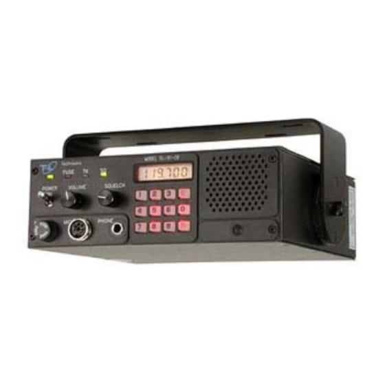
TECHNISONIC INDUSTRIES LIMITED www.til.ca Figure 1.1 91-DE Transceiver - General View TMS-150 91-DE Installation & Operating Instructions TiL 94RE146 Rev E... -
Page 12: Power Input Cable Assembly - General View
TECHNISONIC INDUSTRIES LIMITED www.til.ca Figure 1.2 91-DE Transceiver with Mounting Bracket Figure 1.3 Power Input Cable Assembly - General View TMS-150 91-DE Installation & Operating Instructions TiL 94RE146 Rev E... -
Page 13: Microphone Assembly - General View
TECHNISONIC INDUSTRIES LIMITED www.til.ca Figure 1.4 Microphone Assembly - General View TMS-150 91-DE Installation & Operating Instructions TiL 94RE146 Rev E... -
Page 14: Antenna Assembly - General View
TECHNISONIC INDUSTRIES LIMITED www.til.ca Figure 1.5 Antenna Assembly - General View TMS-150 91-DE Installation & Operating Instructions TiL 94RE146 Rev E... -
Page 15: Technical Summary
TECHNISONIC INDUSTRIES LIMITED www.til.ca TECHNICAL SUMMARY A summary of the relevant electrical, operational, mechanical and physical characteristics of the transceiver are given in Table 1.1, Leading Particulars. TABLE 1.1 LEADING PARTICULARS TRANSCEIVER MODEL 91-DE: Power Source Requirements: DC Voltage (Negative Ground) ………………….…………….……………….. 13.75 VDC Nominal Input Current: Transmit Mode …………………………………………….…………………..……….. - Page 16 TECHNISONIC INDUSTRIES LIMITED www.til.ca TABLE 1.1 LEADING PARTICULARS (CONTINUED) RECEIVER CHARACTERISTICS (Continued) Intermodulation: Levels of Interference Signals are shown to produce resulting SINAD of not less than 6dB: Ultimate Sensitivity (12dB) SINAD) …………………………………………………………….. 67 dB 30microvolts, Input Signal ……………………………………………………………………….. 45 dB 300microvolts, Input Signal ……………………………………………………………………...
-
Page 17: Introduction
TECHNISONIC INDUSTRIES LIMITED www.til.ca SECTION 2 – INSTALLATION INFORMATION INTRODUCTION This section gives the basic installation information for units of VHF/AM Mobile Transceiver System 910200 in a typical airport service vehicle. As there are many types of vehicles in use, some may require "tailor made"... -
Page 18: Antenna Assembly
TECHNISONIC INDUSTRIES LIMITED www.til.ca ANTENNA ASSEMBLY Antenna Assembly, Part Number 861910-1, is supplied as a kit which includes an installation leaflet. The antenna is shown assembled in Figure 1.5. 2.5.1 Antenna Location The antenna location is a very important factor in determining the performance of the system. The antenna may be mounted on any flat surface, roof, cowl, fender or rear deck of the vehicle, however, rooftop mounting is recommended for best performance. -
Page 19: Optional External Loudspeaker Or Headphone
TECHNISONIC INDUSTRIES LIMITED www.til.ca OPTIONAL EXTERNAL LOUDSPEAKER OR HEADPHONE Provision is made for connection of either an external loudspeaker or headphone to the SPEAKER/PHONE jack of the transceiver, as shown in Figure 3.1. 2.9.1 External Loudspeaker When an external loudspeaker is to be installed, an 8-ohm nominal impedance loudspeaker should be used. - Page 20 TECHNISONIC INDUSTRIES LIMITED www.til.ca This page left intentionally blank. TMS-150 91-DE Installation & Operating Instructions TiL 94RE146 Rev E...
-
Page 21: Operating Instructions
121.500 MHz. The TiL-91-DE transceiver was available in either 10 or 25 channel versions until July 2012. The 25 channel version can be identified by ‘25’ or ‘1283T’ on the option label on those units. All units manufactured after July 2012 are 25 channel only. - Page 22 TECHNISONIC INDUSTRIES LIMITED www.til.ca Figure 3.1 91-DE Mobile Transceiver Front and Rear Panel Layout TMS-150 91-DE Installation & Operating Instructions TiL 94RE146 Rev E...
-
Page 23: Operator's Switches, Controls And Indicators
TECHNISONIC INDUSTRIES LIMITED www.til.ca TABLE 3.1 OPERATORS SWITCHES, CONTROLS AND INDICATORS SWITCHES CONTROLS & FUNCTIONAL DESCRIPTION INDICATORS POWER A toggle switch applies the 13.7 volts nominal power supply to the ON/OFF transceiver. The transceiver is switched to ON in the toggle UP position and SWITCH is switched OFF in the toggle DOWN position. - Page 24 TECHNISONIC INDUSTRIES LIMITED www.til.ca TABLE 3.1 OPERATORS SWITCHES, CONTROLS AND INDICATORS (Continued) SWITCHES CONTROLS & FUNCTIONAL DESCRIPTION INDICATORS LIQUID A 5½ digit Liquid Crystal Display (LCD) displays the FREQUENCY/ CRYSTAL CHANNEL that the transceiver is currently operating on. In SCAN mode it DISPLAY displays the current frequency scanned if RF signal is present.
-
Page 25: Front Panel Keypad Operation (10 Or 25 Channel Memories)
FRONT PANEL KEYPAD OPERATION Note: The TiL-91-DE transceiver was available in either 10 or 25 channel versions until July 2012. The 25 channel version can be identified by ‘25’ or ‘1283T’ on the option label on those units. All units manufactured after July 2012 are 25 channel only. -
Page 26: Keypad "Beeps
TECHNISONIC INDUSTRIES LIMITED www.til.ca 3.3.1 Keypad "Beeps" Audible "Beeps" are generated when a key is pressed (default condition). Beeps can be enabled/disabled by toggling the "E","8" keys. Press to disable Key "Beeps". Press to enable Key "Beeps". 3.3.2 Keypad and LCD Display Lighting Three Display and keypad lighting modes are available to the operator. -
Page 27: Selecting A Frequency
TECHNISONIC INDUSTRIES LIMITED www.til.ca 3.3.4 Selecting a Frequency To select a frequency, press the keypad digits in the sequence indicated (Refer to Fig 3.1 Base Station Front and Rear Panel Layout). 1st digit - must be 1 for 100 MHz, all other digits are ignored. -
Page 28: Storing A Frequency To A Channel
TECHNISONIC INDUSTRIES LIMITED www.til.ca 3.3.5 Storing a Frequency to a Channel Up to 10 Frequencies can be stored and recalled in channels 0 to 9 as follows or, up to 26 Frequencies can be stored and recalled in channels 00 to 25 as follows: Enter the frequency to be stored as described in paragraph 3.3.4 (Selecting a Frequency) -
Page 29: Transmit Inhibit
TECHNISONIC INDUSTRIES LIMITED www.til.ca 3.3.7 Transmit Inhibit To Inhibit the transmit function on a desired channel press "E","9" immediately followed by the channel "#" or “##” to be inhibited. Subsequent pressing of "E","9","#" or "E","9","##" will enable the transmit function. -
Page 30: Search Mode
TECHNISONIC INDUSTRIES LIMITED www.til.ca 3.3.9 Search Mode In SEARCH MODE the receiver steps through each stored channel until a signal is found. The receiver will lock on to the first signal strong enough to quiet the squelch circuit. SEARCH mode is exited when a signal is found. - Page 31 TECHNISONIC INDUSTRIES LIMITED www.til.ca Figure 3.2 Fixed Channel Jumper Locations TMS-150 91-DE Installation & Operating Instructions TiL 94RE146 Rev E 3-11...
-
Page 32: System Configuration
TECHNISONIC INDUSTRIES LIMITED www.til.ca CHANNEL FREQUENCY SELECTION The following procedure disables keypad entry of frequencies so that the operator will only be able to select stored channels for receive or transmit. 3.4.1 System Configuration Configure channel frequencies as desired (Refer to Section 3.3.5). -
Page 33: Warranty
Tel: (905) 890-2113 Fax: (905) 890-5338 IMPORTANT WARRANTY All communication equipment manufactured by Technisonic Industries Limited is warranted to be free of defects in Material or Workmanship under normal use for a period of one year from Date of Purchase by the end user.
Need help?
Do you have a question about the TiL-91-DE and is the answer not in the manual?
Questions and answers