Technisonic Industries Limited TDFM-6000 Installation And Operating Instructions Manual
Multiband p25 airborne transceiver
Hide thumbs
Also See for TDFM-6000:
- Installation and operating instructions manual (34 pages) ,
- Maintenance manual (363 pages)
Table of Contents
Advertisement
Quick Links
Advertisement
Table of Contents

Related Manuals for Technisonic Industries Limited TDFM-6000


Summary of Contents for Technisonic Industries Limited TDFM-6000
- Page 1 MULTIBAND P25 AIRBORNE TRANSCEIVER MODEL TDFM-600/6000 Installation and Operating Instructions Til Document No. 01RE293 Rev. C August 2002 Technisonic Industries Limited 240 Traders Blvd, Mississauga, Ontario L4Z 1W7 Tel:(905)890-2113 Fax:(905)890-5338 www.til.ca...
- Page 2 WARRANTY INFORMATION The Model TDFM-600/6000 Transceiver is under warranty for one year from date of purchase. Failed units caused by defective parts, or workmanship should be returned to: Technisonic Industries Limited Technisonic Industries Limited 240 Traders Boulevard 3840 E. Robinson Road, Suite 214...
-
Page 3: Table Of Contents
TABLE OF CONTENTS Paragraph Title Page SECTION 1 GENERAL DESCRIPTION Introduction ....................1-1 Description ....................1-1 Technical Summary..................1-1 SECTION 2 OPERATING INSTRUCTIONS General ......................2-1 2.14 Radio Service Software.................2-4 SECTION 3 INSTALLATION INSTRUCTIONS General ......................3-1 Equipment Packing Log.................3-1 Transceiver Installation .................3-1 Installation Kit - Contents................3-1 Pin Locations and Connections ..............3-2 Wiring Instructions ..................3-3 3.17... -
Page 4: General Description
SECTION 1 GENERAL DESCRIPTION INTRODUCTION This publication provides operating and installation information on the TDFM-600/6000 airborne transceiver. (The exact model number depends on which and how many RF modules are installed.) DESCRIPTION The TDFM-600/6000 series of transceivers are airborne multiband radios capable of conventional FM, P25, SmartNet and SMART ZONE trunking systems. -
Page 5: Operating Instructions
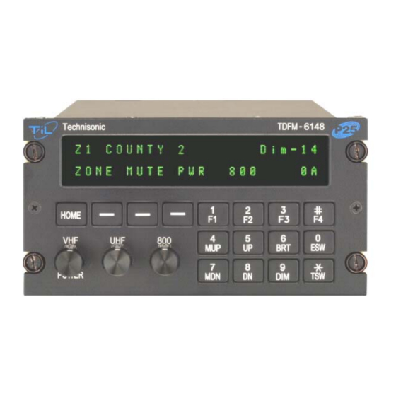
SECTION 2 OPERATING INSTRUCTIONS GENERAL A 2 line display and a keypad and 2 or 3 rotary knobs provide the operator control of the 2 or 3 RF modules installed in the unit. The display is showing the activity of one RF module at a time, selected by pressing the desired knob. - Page 6 KNOBS The transceiver will have two or three knobs depending on how many RF modules are installed. The knobs are rotary encoders which turn endlessly which means their actual position is not important. Each knob also has a push button incorporated in it so you can press the knob as well as turn it. Pressing a different knob will cause the display and keyboard to switch to the band associated with that knob.
- Page 7 TDFM-600/6000 Transceiver Recommended Keypad Menu Defaults: TDFM-600/6000 Portable Conventional SmartNet SMARTZONE Operation (H35) Operation (H37) Operation (H38) ITEM ITEM F1 Key Top Side Monitor Phone Phone Button 1 F2 Key Center Side Scan Scan Scan Button 2 F3 Key Bottom Side Talkaround/ Private Call Site...
- Page 8 The following settings must be programmed for each mode in a Trunked (SmartNet or SMARTZONE) Radio: System Type TG Strapping System ID Zone Individual ID Scan List Coverage Type Scan Type Affiliation Type Interconnect Control Channel 1 Phone Display Format Control Channel 2 Private Call Talkgroup 1...
-
Page 9: Radio Service Software
2.12 DISPLAY The transceiver has a two line, 48 character LED display which gives information about the selected band. On the top line is shown the zone number, channel name and rotary knob function. The bottom line displays the soft key menu, the band selected, and the ESW/TSW condition. Also displayed are letters and symbols indicating scan, direct/repeater talk around, monitor, secure, priority and call. -
Page 10: Installation Instructions
SECTION 3 INSTALLATION INSTRUCTIONS GENERAL This section contains information and instructions for the correct installation of the TDFM-600/6000 Transceiver. EQUIPMENT PACKING LOG Unpack the equipment and check for any damage that may have occurred during transit. Save the original shipping container for returns due to damage or warranty claims. Check that each item on the packing slip has been shipped in the container. - Page 11 FIGURE 3-1 Outline Drawing for Model TDFM-600/6000...
-
Page 12: Pin Locations And Connections
INSTALLATION - PIN LOCATIONS AND CONNECTIONS J1 - 25 Pin D Connections - Use FEMALE Connector Pin # Description Ground Main Power +28 VDC Mic 1 Audio 1 PTT 1 Mic 2 Audio 2 PTT 2 Mic 3 Audio 3 PTT 3 TX Data RX Data... - Page 13 3.10 MIC 1, 2 AND 3 - PINS 3, 6 AND 9 The microphone input signals shall be connected using shielded wire with the shield connected to ground (pin 1 or 14). It is recommended for best results to leave the other end of the shield floating to prevent ground currents.
-
Page 14: Wiring Connections And Notes
FIGURE 3-2 Wiring connections and notes for the TDFM-600/6000 Transceiver... - Page 15 3.17 POST INSTALLATION EMI TEST PURPOSE The purpose of this test is to identify any interference that the TDFM-600/6000 transceiver may cause with existing aircraft systems. TEST CONDITIONS The TDFM-600/6000 transceiver should be installed and function tested. The antenna VSWR should be checked.
- Page 16 RESULTS If the installed system passes all of the applicable EMI tests, then no further action is required. If interference is observed then the interference must be assessed against the appropriate standards of airworthiness for the system in question. For example it is permissible for a VFR certified GPS to lose navigation capability while the TDFM-600/6000 unit is transmitting, providing that it recovers properly and promptly, but it is not permissible for an IFR Approach certified GPS to be affected in the same way.
- Page 17 FREQUENCIES RESULTS VHF #1 TDFM-600/6000 PASS FAIL 135.975 136.0000 121.150 157.5000 131.250 157.5000 Image: FREQUENCIES RESULTS VHF #2 TDFM-600/6000 PASS FAIL 135.975 136.0000 121.150 157.5000 131.250 157.5000 Image: NOTES: Determine if the image frequency for the VOR/ILS Nav falls within the range of the TDFM- 600/6000.
- Page 18 FREQUENCIES RESULTS VOR/ILS #2 TDFM-600/6000 PASS FAIL 108.000 162.0000 108.100 162.1500 Image: NOTES: Modulate the TDFM-600/6000 transmitter on the following frequencies for at least 20 seconds. Observe the Glideslope displays. Look for any movement of flags or needles on the navigation display.
- Page 19 Operate the TDFM-600/6000 transmitter on the following frequency for at least 20 seconds. Observe the Transponder for any spurious replies or loss of reply to test set. FREQUENCIES TRANSPONDER #1 TRANSPONDER #2 TDFM-600/6000 PASS FAIL PASS FAIL 512 MHZ NOTES: Modulate the TDFM-600/6000 transmitter on the following frequencies for at least 20 seconds.
- Page 20 NOTE: For the following tests, select a frequency at the top, middle and bottom of each band of the TDFM- 600/6000 transceiver. 806 to 870 136 to 178 403 to 470 450 to 512 MHZ Band MHZ Band MHZ Band MHZ Band Frequency Frequency...
- Page 21 List the power plant, fuel and other electric instruments in the chart provided and note any anomalies that occur while transmitting. Assess the results. STEP SYSTEM PASS FAIL NOTES Com 1&2 (UHF Lo, UHF Hi, and 800 MHz) Transponder & Encoder (VHF, UHF Lo, and 800 MHz) ADF 1 &...
- Page 22 STEP SYSTEM PASS FAIL NOTES Amps Bus Voltage Fuel % Torque % Annunciators Digital Clock Oil Pressure DME 1&2 (VHF, UHF Lo, and 800 MHz) GPS 1&2 (UHF Lo and 800 MHz) 3-13...
- Page 23 STEP SYSTEM PASS FAIL NOTES NOTES: 3-14...
Need help?
Do you have a question about the TDFM-6000 and is the answer not in the manual?
Questions and answers