Table of Contents
Advertisement
Quick Links
VHF/AM MOBILE TRANSCEIVER
Model TiL-90-6R
MOBILE SYSTEM P/N 860605
(TMS-100)
Installation and
Operating Instructions
TiL Document No. 89RE190
Rev. F
JULY 2012
Technisonic Industries Limited
240 Traders Boulevard, Mississauga, Ontario L4Z 1W7
Tel: (905) 890-2113 Fax: (905) 890-5338
www.til.ca
Copyright by Technisonic Industries Limited. All rights reserved.
Advertisement
Table of Contents

Related Manuals for Technisonic Industries Limited TiL-90-6R


Summary of Contents for Technisonic Industries Limited TiL-90-6R
- Page 1 MOBILE SYSTEM P/N 860605 (TMS-100) Installation and Operating Instructions TiL Document No. 89RE190 Rev. F JULY 2012 Technisonic Industries Limited 240 Traders Boulevard, Mississauga, Ontario L4Z 1W7 Tel: (905) 890-2113 Fax: (905) 890-5338 www.til.ca Copyright by Technisonic Industries Limited. All rights reserved.
- Page 3 REVISION HISTORY [ 89RE190 ] SECTION Edited DESCRIPTION DATE - PAGE - Original Document Global New Document Template (new file format) Title page changed, Headers/Footers added Added Revision page, Added Warranty page Added note to §2.4 Channel Freq. Selection DEC 2011 referring to units built after Jan 2012 with a USB port and added Appendix A (TDP-90 for USB AM units) with Installation and Operating Instructions.
- Page 4 iiii...
- Page 5 WARRANTY INFORMATION The TMS-100 Mobile System is under warranty for one year from date of purchase. Failed units caused by defective parts, or workmanship should be returned to: Technisonic Industries Limited 240 Traders Boulevard Mississauga, Ontario L4Z 1W7 Tel: (905) 890-2113...
-
Page 7: Table Of Contents
TECHNISONIC INDUSTRIES LIMITED www.til.ca TABLE OF CONTENTS SECTION TITLE PAGE SECTION 1 GENERAL DESCRIPTION INTRODUCTION ....................... 1-1 1.1.1 Purpose of the System ...................... 1-1 1.1.2 Modes of Operation ......................1-2 TECHNICAL SUMMARY ....................1-8 SECTION 2 CHANNEL FREQUENCY SELECTION AND INSTALLATION INTRODUCTION ....................... - Page 8 TECHNISONIC INDUSTRIES LIMITED www.til.ca LIST OF FIGURES FIGURE TITLE PAGE Transceiver - General View ...................... 1-3 Transceiver with Mounting Bracket - General View ..............1-4 Power Input Cable Assembly - General View ................1-5 Microphone Assembly - General View ..................1-6 Antenna Assembly - General View....................
-
Page 9: General Description
TECHNISONIC INDUSTRIES LIMITED www.til.ca SECTION 1 - GENERAL DESCRIPTION INTRODUCTION VHF/AM Mobile Transceiver System 860605 (TMS-100), manufactured by Technisonic Industries Limited, is a low power VHF/AM Transceiver, complete with Mounting Bracket, Power Input Cable, Microphone and Antenna. 1.1.1 Purpose of the System... -
Page 10: Modes Of Operation
TECHNISONIC INDUSTRIES LIMITED www.til.ca The microphone dc supply for the microphone is supplied by the transceiver. The mounting bracket, provided with the microphone, should be mounted in a convenient location near the transceiver. A small screwdriver which can be used for releasing the modular plug located in the microphone head is supplied with the microphone. -
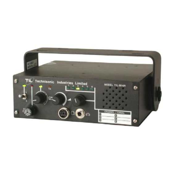
Page 11: Transceiver - General View
TECHNISONIC INDUSTRIES LIMITED www.til.ca Figure 1.1 Transceiver - General View TMS-100 90-6R Installation & Operating Instructions TiL 89RE190 Rev F... -
Page 12: Transceiver With Mounting Bracket - General View
TECHNISONIC INDUSTRIES LIMITED www.til.ca Figure 1.2 Transceiver with Mounting Bracket - General View TMS-100 90-6R Installation & Operating Instructions TiL 89RE190 Rev F... -
Page 13: Power Input Cable Assembly - General View
TECHNISONIC INDUSTRIES LIMITED www.til.ca Figure 1.3 Power Input Cable Assembly - General View TMS-100 90-6R Installation & Operating Instructions TiL 89RE190 Rev F... -
Page 14: Microphone Assembly - General View
TECHNISONIC INDUSTRIES LIMITED www.til.ca Figure 1.4 Microphone Assembly - General View TMS-100 90-6R Installation & Operating Instructions TiL 89RE190 Rev F... -
Page 15: Antenna Assembly - General View
TECHNISONIC INDUSTRIES LIMITED www.til.ca Figure 1.5 Antenna Assembly - General View TMS-100 90-6R Installation & Operating Instructions TiL 89RE190 Rev F... -
Page 16: Technical Summary
TECHNISONIC INDUSTRIES LIMITED www.til.ca TECHNICAL SUMMARY A summary of the relevant electrical, operational, mechanical and physical characteristics of the transceiver are given in Table 1.1, Leading Particulars. TABLE 1.1 LEADING PARTICULARS TRANSCEIVER MODEL 90-6R: Power Source Requirements: DC Voltage (Negative Ground) ............... 13.75Vdc Nominal Input Current:: Transmit Mode ...................... - Page 17 TECHNISONIC INDUSTRIES LIMITED www.til.ca TABLE 1.1 TRM-400 Series Transceivers - LEADING PARTICULARS (Continued) RECEIVER CHARACTERISTICS (Continued) Intermodulation: Levels of Interference Signals Are Shown To Produce Resulting SINAD of Not Less Than 6dB: Ultimate Sensitivity (12dB) SINAD) ..................67 dB 30microvolts, Input Signal ....................45 dB 300microvolts, Input Signal ....................
- Page 18 TECHNISONIC INDUSTRIES LIMITED www.til.ca This page left intentionally blank TMS-100 90-6R Installation & Operating Instructions TiL 89RE190 Rev F 1-10...
-
Page 19: Channel Frequency Selection And Installation
121.9000 MHz, as outlined in paragraph 2.6. If there is any operational deficiency or equipment malfunction, the transceiver is to be returned to the manufacturer Technisonic Industries Limited, under warranty. Before installation in a vehicle, it is necessary to pre-program the operating frequency for each channel to be used at the particular airport. -
Page 20: Pre-Programming Of Channel Frequency
TECHNISONIC INDUSTRIES LIMITED www.til.ca PREPROGRAMMING OF CHANNEL FREQUENCIES Determine the number of channels to be used and the specific frequency of each channel for the particular transceiver being worked on. Prepare a list of channel number and frequencies to be preprogrammed, then proceed as follows: 2.4.1... -
Page 21: Frequency Selection Mhz
TECHNISONIC INDUSTRIES LIMITED www.til.ca TABLE 2.1 FREQUENCY SELECTION MHz OPERATING DIODE LOCATION FREQUENCY (MHz) 20 MHz 10 MHz 8 MHz 4 MHz 2 MHz 1 MHz LEGEND: 0 = NO DIODE REQUIRED 1 = DIODE TO BE INSTALLED TMS-100 90-6R Installation & Operating Instructions... -
Page 22: Frequency Selection Khz
TECHNISONIC INDUSTRIES LIMITED www.til.ca TABLE 2.2 FREQUENCY SELECTION kHz OPERATING DIODE LOCATION FREQUENCY (kHz) 800 kHz 400 kHz 200 kHz 100 kHz 50 kHz 25 kHz LEGEND: 0 = NO DIODE REQUIRED 1 = DIODE TO BE INSTALLED TMS-100 90-6R Installation & Operating Instructions... -
Page 23: Installation Of Module A5
TECHNISONIC INDUSTRIES LIMITED www.til.ca INSTALLATION OF MODULE A5 After frequency selection has been completed, Frequency Set-Memory Module A5 shall be installed in the transceiver as follows: Locate Frequency Set-Memory Module A5 in position, engaging its male pin connector A5J1 into its mating connector A2J2 on Audio Synthesizer Module A2. Gently push Module A5 downwards until it is correctly located. - Page 24 TECHNISONIC INDUSTRIES LIMITED www.til.ca Figure 2.1 Frequency Set-Memory Module A5 - Component Layout TMS-100 90-6R Installation & Operating Instructions TiL 89RE190 Rev F...
-
Page 25: Power Input Cable Assembly
TECHNISONIC INDUSTRIES LIMITED www.til.ca 2.10 POWER INPUT CABLE ASSEMBLY Using Power Input Cable Assembly, Part Number 863701, as shown in Figure 1.3, route the un- terminated end of the cable from the transceiver location to the point of connection to the fused vehicle power supply. -
Page 26: Microphone Installation
TECHNISONIC INDUSTRIES LIMITED www.til.ca 2.15 MICROPHONE INSTALLATION Refer to Figure 1.4 for a general view of the microphone and retaining bracket. Determine a suitable and convenient location for Retaining Bracket and secure it using appropriate hardware (not provided). Connect the connector of Microphone, Part Number 961070-1 to the MIC/PTT connector located on the front panel of the transceiver. -
Page 27: Operating Instructions
TECHNISONIC INDUSTRIES LIMITED www.til.ca SECTION 3 – OPERATING INSTRUCTIONS INTRODUCTION This section includes a functional description of each switch, control, indicator and connector located on the front panel of the transceiver, together with the PRESS-TO-TALK switch included on the microphone, together with operating instructions. -
Page 28: Operator's Switches, Controls And Indicators
TECHNISONIC INDUSTRIES LIMITED www.til.ca TABLE 3.1 OPERATORS SWITCHES, CONTROLS AND INDICATORS SWITCHES CONTROLS & FUNCTIONAL DESCRIPTION INDICATORS POWER ON/OFF A two-position toggle switch which controls the application of the 12 volts nominal SWITCH power supply to the transceiver. Position 1, toggle UP, the transceiver is switched ON. - Page 29 TECHNISONIC INDUSTRIES LIMITED www.til.ca TABLE 3.1 OPERATORS SWITCHES, CONTROLS AND INDICATORS (Continued) SWITCHES CONTROLS & FUNCTIONAL DESCRIPTION INDICATORS MICROPHONE When connected via the MIC/PTT CONNECTOR to the transceiver, the PRESS- PRESS-TO-TALK TO-TALK (PTT) switch determines the operating mode of the transceiver.
-
Page 30: Preparation For Use
TECHNISONIC INDUSTRIES LIMITED www.til.ca PREPARATION FOR USE To prepare the transceiver for use: Remove the microphone from its mounting bracket, and ensure that the microphone connector is connected to the MIC/PTT connector of the transceiver. Set the SQUELCH control in the fully counter-clockwise (CCW) position. -
Page 31: Operation In The Receive Mode
TECHNISONIC INDUSTRIES LIMITED www.til.ca OPERATION IN THE RECEIVE MODE To operate the transceiver in the receive mode, proceed as follows: Ensure that the PRESS-TO-TALK switch on the microphone is NOT depressed, and verify that the Tx ON yellow LED is OFF. - Page 32 TECHNISONIC INDUSTRIES LIMITED www.til.ca This page left intentionally blank TMS-100 90-6R Installation & Operating Instructions TiL 89RE190 Rev F...
-
Page 33: Warranty
Tel: (905) 890-2113 Fax: (905) 890-5338 IMPORTANT WARRANTY All communication equipment manufactured by Technisonic Industries Limited is warranted to be free of defects in Material or Workmanship under normal use for a period of one year from Date of Purchase by the end user. -
Page 35: Programming Software
Technisonic Industries Ltd. TiL TDP-90 Programming Software User’s Guide for USB Programmable AM Series Transceivers DOCUMENT No. 11RE439 REVISION DATE OF ISSUE JULY 19, 2012 Technisonic Industries Limited 240 Traders Boulevard, Mississauga, Ontario L4Z 1W7 Tel: (905) 890-2113 Fax: (905) 890-5338 www.til.ca... - Page 36 This page left intentionally blank.
- Page 37 APPENDIX A 11RE439 Rev A INTRODUCTION This document contains instructions for proper installation and operation of the TDP 90 software for USB programmable Technisonic AM series transceivers and details the various elements of the Graphical User Interface (GUI). NOTE: The images in this document are examples only and may not reflect your particular data settings, or current TDP software version.
- Page 38 APPENDIX A 11RE439 Rev A GETTING STARTED To start the TDP 90 program, double click the TDP90 icon on the desktop. The following Graphical User Interface will appear. The current version number is shown in square brackets on the title bar. MAIN GRAPHICAL USER INTERFACE Figure 1...
- Page 39 APPENDIX A 11RE439 Rev A ICONS AND PULL DOWN MENUS The icons and pull-down menus provide the set-up and operating functions. The Channels pull-down tab provides selection for single or six channel transceivers (use the 6 channel window for 4 channel transceivers). The number of channels in the Frequency editing window changes accordingly.
- Page 40 APPENDIX A 11RE439 Rev A FILE MENU Figure 3 Open will allow you to select and load an existing file that was previously saved on disk. The yellow folder icon provides the same function in a single mouse click. Save will allow you to save the current data into a file with a name of your choice. The filename may be any length up to 64 characters.
- Page 41 APPENDIX A 11RE439 Rev A DATA MENU Figure 4 Download (to Radio) instructs the TDP 90 software to transfer the frequency data in the list to the memory channels in the connected AM transceiver. The Dn icon provides the same function in a single mouse click.
- Page 42 APPENDIX A 11RE439 Rev A HELP MENU Figure 5 TDP-90 Help Contents opens the Windows Help dialog for the TDP-90 software. Here, you will find hardware connection and operating information as well as troubleshooting tips and answers to some Frequently Asked Questions. About selection displays Technisonic company and contact information as well as the revision number of the TDP software in the “Terminal window”...
- Page 43 APPENDIX A 11RE439 Rev A CHANNEL SELECTION PULLDOWN 1 CHANNEL TRANSCEIVER Figure 6 6 CHANNEL TRANSCEIVER Figure 7 The x Channel(s) pull-down tab allows you to select for single or six channel AM transceiver use. The frequency editing window changes accordingly. The “W” indicates that the channels are 25kHz (Wide) channel spacing and as such, only channels in 25kHz increments are accepted.
- Page 44 APPENDIX A 11RE439 Rev A SAMPLE UPLOAD AND DOWNLOAD Connect the transceiver to the computer USB port using a standard USB-A male to USB- B male cable. The USB port is located on the rear panel of mobile and base station transceivers and on the front panel of rack mount transceivers.
Need help?
Do you have a question about the TiL-90-6R and is the answer not in the manual?
Questions and answers