Technisonic Industries Limited TFM-138 Series Installation And Operating Instructions Manual
Airborne vhf fm transceivers
Hide thumbs
Also See for TFM-138 Series:
- Installation and operating instructions manual (43 pages) ,
- Operator's manual (17 pages)
Table of Contents
Advertisement
MODEL TFM-138 SERIES
Airborne VHF FM Transceivers
Technisonic VHF FM Airborne Transceivers
Technisonic TFM-138 series airborne VHF/FM transceivers utilize state of the art frequency synthesis
techniques to provide FM communications on every currently available channel within the VHF/FM High
Band. These radios cover the entire band from 138 to 174 MHz in 2.5 KHz increments. Data entry and
function control are via a front panel 12 button keypad. Operating frequency and other related data are
presented on a 48 character two line LED matrix display which is available in either green or red.
Technisonic FM transceivers can be operated in the Direct Entry or Simplex mode by simply keying in the
desired operating frequency, or can function without restriction on any split frequency pair within the band.
The TFM-138 features 100 preset memory positions each of which is capable of storing a receive
frequency, a transmit frequency, a separate CTCSS tone for each receive and transmit frequency and an
alpha numeric identifier for each channel. The TFM-138B features similar storage capability, but provide for
120 channels of preset memory, and offer the additional capability of allowing for DPL (Digital Private Line)
or DCS (Digitally Coded Squelch) operation. The TFM-138 and TFM-138B allows either 25 kHz wide band
or 12.5 kHz narrow band operation on any or all their preset memory channels. Data can be easily entered
into any of the preset non-volatile memory positions for both main and guard channels via the front panel
keyboard. Information stored in memory is available for instant recall by keypad entry, or by pressing the
UP or DOWN button which allows the operator to scroll through all preset channels. Technisonic FM
transceivers feature a synthesized two channel guard, receiver, a DTMF encoder for signaling during
transmit, and a scan function which will scan any or all of the frequencies stored in the preset memory
positions.
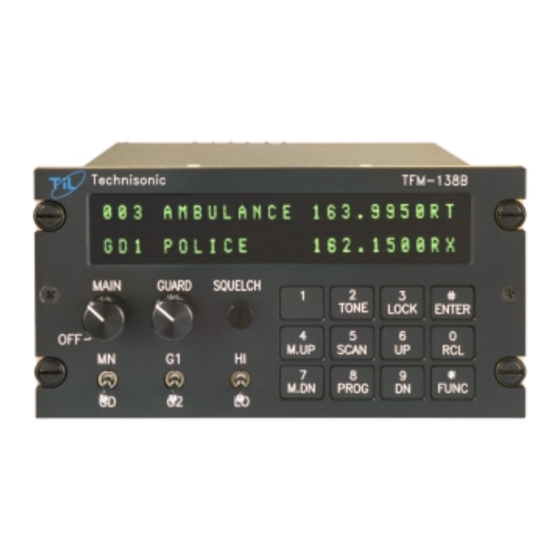
TFM-138 series transceivers are panel mounted (Dzus mounting) and are completely self contained in a 8.0
x 3.0 x 5.75 inch chassis weighing just 3.1 pounds. Front panel controls are MAIN for main channel
volume; GUARD for guard channel volume; MON for squelch test; a MN/GD switch provides for main or
guard transmitter selection; a G1/G2 switch selects guard 1 or guard 2 receive and transmit; and a HI/LO
switch allows for control of transmitter power output. Hi power is 10 Watts output, low power is 1 Watt
output, which is necessary to comply with Marine harbor environment rules. These transceivers offer 28
volt DC backlighting, which is controlled by the aircraft dimmer bus. Display brightness is controlled from
the front panel keypad. The small size and light weight of TFM-138 series transceivers make them ideally
suited to helicopter installations
Technisonic FM transceivers are compliant with RTCA DO-160C
categories relating to Vibration, Overpressure, Humidity, Temperature and Altitude, Magnetic Effect, Power
Input, Voltage Spike, Decompression, and RF emission (including Section 21, Category Z)
Advertisement
Table of Contents

Related Manuals for Technisonic Industries Limited TFM-138 Series


Summary of Contents for Technisonic Industries Limited TFM-138 Series
- Page 1 Marine harbor environment rules. These transceivers offer 28 volt DC backlighting, which is controlled by the aircraft dimmer bus. Display brightness is controlled from the front panel keypad. The small size and light weight of TFM-138 series transceivers make them ideally suited to helicopter installations...
- Page 2 General Specifications Model Designation TFM-138 TFM-138B Frequency Range 138.000 MHz to 174.000 MHz 138.000 MHz to 174.000 MHz Tuning increments 2.5 kHz 2.5 kHz Operating Mode F3E simplex or semi-duplex F3E simplex or semi-duplex Channel spacing 25 kHz or 30 kHz as per applicable 12.5 kHz, 25 kHz or 30 kHz as per FCC and DOC specifications applicable FCC and DOC spec.
- Page 3 AIRBORNE TRANSCEIVER MODEL TFM-138 s/n’s 1540 and up with F10-B Software Installation and Operating Instructions Til Document No. 98RE229 Rev. A Issue 2 AUGUST 2010 Technisonic Industries Limited 240 Traders Boulevard, Mississauga, Ontario L4Z 1W7 Tel:(905)890-2113 Fax:(905)890-5338 web site: www.til.ca...
- Page 4 WARRANTY INFORMATION The Model TFM-138, VHF/FM Transceiver is under warranty for one year from date of purchase. Failed units caused by defective parts, or workmanship should be returned to: Technisonic Industries Limited 240 Traders Boulevard Mississauga, Ontario Canada L4Z 1W7...
- Page 5 Summary of DO-160C Environmental Testing for Technisonic Model TFM-138, VHF Transceiver Conditions Section Description of Conducted Tests Temperature and Altitude Equipment tested to categories B2 and Vibration Equipment is tested without shock mounts to categories B, M and N. Magnetic Effect 15.0 Equipment is class Z.
-
Page 6: Table Of Contents
TABLE OF CONTENTS Paragraph Title Page SECTION 1 GENERAL DESCRIPTION Introduction ..........1-1 Description . - Page 7 INSTALLATION INSTRUCTIONS - APPENDIX Post Installation EMI Test ........A-1 LIST OF TABLES Table No.
- Page 8 TFM-138 SOFTWARE CHANGE NOTE This document covers operation of the Technisonic TFM-138, s/n 1540 and onwards which have been delivered from the factory with version F10-B software capable of wide/narrow band operation. For TFM-138’s with s/n 1539 or less, TiL Document 95RE177 should be referred to. This document does not cover the operation of older version TFM-138’s with s/n 1539 or less.
-
Page 9: General Description
SECTION 1 GENERAL DESCRIPTION INTRODUCTION This publication provides operating and installation information on the TFM-138 (with version F10-B software), Transceiver manufactured by Technisonic Industries Ltd. The version F10-B software is factory installed in TFM-138's with s/n F1540 and onwards. The unit offers an extended frequency range with selectable channel spacing and is intended for use (in the U.S.) only by government agencies or contractors thereto, who have obtained licensing for operation in the 138-150 MHz portion of the band. - Page 10 TECHNICAL CHARACTERISTICS Specification Characteristic GENERAL Model Designation: TFM-138, s/n 1540 and up Frequency Range: 138.000 to 174.000 MHz Tuning Increments: 2.5 kHz Operating Mode: F3E simplex or semi-duplex Channel Spacing: 25 or 12.5 kHz Physical Dimensions (including heatsink): Approx. 8.0" X 3.0" X 5.75" Weight: Approx.
- Page 11 TECHNICAL CHARACTERISTICS (continued) MAIN RECEIVER Sensitivity at 12 dB SINAD Better than 0.35 µV Adjacent Channel Selectivity -70 dB (25 or 12.5 kHz) Spurious Attenuation -90 dB Third Order Intermodulation -70 dB Image Attenuation -80 dB FM Acceptance ± 6 kHz Hum and Noise Better than 50 dB Audio Distortion...
-
Page 12: Operating Instructions
SECTION 2 OPERATING INSTRUCTIONS OPERATING FEATURES The equipment has several important operating features which provide maximum flexibility, performance and versatility. These features are outlined below. New features provided in TFM-138 units of s/n 1540 and up with F10-B software are indicated by an “*”. 100 memory positions* which can each be programmed with a transmit and receive frequency with 25 or 12.5 kHz channel spacing*, Tx/Rx CTCSS tones and a 9- character alphanumeric title. - Page 13 FIGURE 2-1 Operator's Switches and Controls - TFM-138, (F10-B software)
-
Page 14: Programming Instructions
Only TX CTCSS tones may be programmed for the guard receiver. At the beginning of each line, an LED indicates open squelch. Set the MN/GD switch to main or guard transmit frequency. Set the G1/G2 switch to the desired guard channel. Set the HI/LO switch to the desired RF output power. -
Page 15: Scanning Function
The alpha-numeric title is now displayed. Use the M.UP and M.DN keys to scroll through the alphabet, numbers and symbols. When the desired character is displayed, press ENTER to advance to the next character. Keep repeating step six until the last space is set. The display will show SCAN or LOCKOUT to enable this memory position as part of the scan list or lock it out of the scan list. -
Page 16: Priority And Selective Memory Channel Scanning
PRIORITY AND SELECTIVE MEMORY CHANNEL SCANNING The priority memory channel is always memory position number 1. The priority memory channel is scanned every other step (ie. 121314151...) to ensure that no incoming messages are missed. The priority channel can be locked out, which will result in the normal scanning of the other memory positions. -
Page 17: Led Display Variable Dimming Mode
2.10 LED DISPLAY VARIABLE DIMMING MODE With the transceiver in normal operating mode press the UP or DN keys to increase or decrease the intensity of the LED display. Once maximum intensity of the display is acheived, the UP key no longer functions. Conversely once minimum intensity is reached, the DN key ceases to function. -
Page 18: Pc Memory/Programming Download Capability
2.13 PROGRAMMING CTCSS TONES/DPL CODES - continued 82.5 192.8 206.5* 85.4 203.5 210.7* 88.5 33.0* 218.1* 91.5 35.4* 225.7* 94.8 36.6* 229.1* 97.4 37.9* 233.6* 100.0 39.6* 241.8* 103.5 44.4* 250.3* 107.2 47.5* No Tone 110.9 49.2* (carrier squelch only) 114.8 51.2* (The tones marked with * are... - Page 19 Pentium type processors of 200 MHz or less running MS DOS seem to work the best. Please check the “Programmer downloads” link on our web site www.til.ca for further information regarding PC programming information for users of single band transceivers like the TFM-138. Please note that the TFM-138 and not the TFM-138B must be selected in the Multi-TDP software package.
- Page 20 Pull down the Com Port menu and select the com port that you have connected the PIB-100. The software is now ready to use. To get a full instruction manual, pull down the Help menu and select Documentation in PDF format. 2.14.5 Helpful Hints: When uploading or downloading, a message box will appear asking you to press FUNC and then...
- Page 21 Follow the menus to edit channels, print channel list, up or download as desired. The data file is continuously updated as each change is made, so you don’t have to save the file at any time. To have multiple data files, you will have to copy the data file to another name and then copy it back when needed.
- Page 22 TFM-138 Upload/Download Programming Cable For DOS Program P/N 943165-4 - Wiring Diagram FIGURE 2-2 TFM-138 Transceiver PC Download Cable - wiring diagram (for DOS program only) 2-11...
-
Page 23: Installation Instructions
ANTENNA INSTALLATION Antenna, P/N ATM-150 may be obtained from Technisonic Industries Limited or a suitable equivalent may be utilized with the TFM-138 Series transceivers. The antenna should be mounted on the bottom of the aircraft whenever possible. Consult with instructions provided with the antenna. - Page 24 FIGURE 3-1 Outline Drawing for Model TFM-138 Transceiver...
-
Page 25: Wiring Instructions
INSTALLATION - PIN LOCATIONS AND CONNECTIONS (continued) TFM-138 Transceiver 15-Pin D Connections Pin # Description 600 Ohm Output Data Output Panel Lighting (28VDC or 5VAC) Memory UP/PC Download Input Memory Down/PC Download Input Mic Signal Input Main Power +28VDC Main Ground 4 ohm Speaker Output 4 ohm/600 ohm Output Ground Data Input... - Page 26 Figure 3-2 Wiring Connections for TFM-138 Transceiver...
-
Page 27: Front Panel Back Lighting
3.7.4 Front Panel Back Lighting Front panel back lighting connection should be made on pin 3 of the transceiver. The opposite end of this lead should be connected to the panel lighting system of the aircraft. Before connecting, verify the required panel lighting voltage (28 VDC or 5VAC) on the transceiver configuration control label. - Page 28 Microprocessor Control Unit (MCU) PCB Module Notes: R23 is High Power Adjustment R24 is Low Power Adjustment J15 Jumper between pins 3 and 4 for Entry Enable Remove for Entry Disable FIGURE 3-3 Internal Enable/Disable Jumper and Transmit High/Low Power Adjust Locations...
-
Page 29: Transmitter Power Adjustments
TRANSMITTER POWER ADJUSTMENTS The transmitter power is adjusted to a maximum of 10 watts in high power mode and 1 watt in low power mode over the transceiver operating bandwith at the factory. If transmitter RF power re-adjustment is required, perform as follows: Remove bottom cover as described in the previous paragraph (3.8). - Page 30 FIGURE 3-4 Microphone and Sidetone Level, Main and Guard Squelch Adjustment Access Holes...
-
Page 31: Main And Guard Squelch Adjustment
3.12 MAIN AND GUARD SQUELCH ADJUSTMENT The squelch on both the main and guard receivers is factory set to open at approximately 1.0 microvolt. This adjustment can be made or altered to suit local conditions as follows: Set the main receiver of the transceiver to 156.000 MHz. Connect a signal generator to the antenna input of the transceiver. - Page 32 Main Receiver/Transmitter PCB Module Notes: R30 is for 5.0 kHz (wideband) Deviation Adjustment R76 is for 2.5 kHz (narrowband) Deviaton Adjustment FIGURE 3-5 Deviation Adjustment Potentiometer Location...
- Page 33 TFM-138 series transceivers in this document. TEST CONDITIONS The TFM-138 series transceiver should be installed and function tested. The antenna VSWR should be checked. A forward/reverse power check with a in-line wattmeter should show no more than 10% reflected power. For the following tests, insure that the power switch is in the high position.
- Page 34 PROCEDURE Operate the TFM-138 transmitter on the following frequencies for at least 20 seconds. Observe the GPS for any degradation in satellite status or availability or flags. FREQUENCIES GPS #1 GPS #2 TFM 138 PASS FAIL PASS FAIL 143.180 MHz 143.1825 MHz 157.5000 MHz 157.5425 MHz...
- Page 35 Determine if the image frequency for the VHF Comm falls within the range of the TFM-138 series unit. If so, select a set of frequencies that will cause the TFM-138 unit to be set as close as possible to the image frequency. Any one of the many possible sets will suffice. Record those values in the spaces provided in the following chart.
- Page 36 Determine if the image frequency for the VOR/ILS Nav falls within the range of the TFM-138 unit. If so, select a two sets of frequencies that will cause the TFM-138 transceiver to be set as close as possible to the image frequency. Chose one set in the localizer frequency range, and one in the VOR frequency range.
- Page 37 The following procedure checks for second harmonic interference to the glide slope receiver from the TFM-138. All transceivers produce harmonics (multiples of the wanted frequency) and while the TFM-138 far exceeds FCC requirements, interference can still be experienced depending upon antenna position and separation. Furthermore, harmonics can be generated by other equipment in the aircraft and the structure of the aircraft where dissimilar metals make contact or where grounds are isolated, etc.
- Page 38 FREQUENCIES RESULTS G/S #1 TFM-138 PASS FAIL 334.7 (108.1) 167.3500 FREQUENCIES RESULTS G/S #1 TFM-138 series PASS FAIL 334.7 (108.1) 167.3500 NOTES...
- Page 39 NOTE: For the following tests, select a frequency at the top, middle and bottom of the range of the TFM -138 series transceiver. Frequency #1 ______________ Frequency #2 ______________ Frequency #3 ______________ At a safe altitude engage the autopilot or stability augmentation system. Modulate the TFM- 138 transmitter on the above frequencies for at least 20 seconds.
- Page 40 List the power plant, fuel and other electric instruments in the chart provided and note any anomalies that occur while transmitting. Assess the results. STEP SYSTEM PASS FAIL NOTES Xponder & Encoder ADF 1 & 2 Compass Directional Gyro Oil Pressure Fuel Pressure Oil Temp Amps...
- Page 41 STEP SYSTEM PASS FAIL NOTES Bus Voltage Fuel % Torque % Annunciators Digital Clock A-10...
- Page 42 STEP SYSTEM PASS FAIL NOTES A-11...
- Page 43 STEP SYSTEM PASS FAIL NOTES A-12...
- Page 44 STEP SYSTEM PASS FAIL NOTES NOTES: A-13...
Need help?
Do you have a question about the TFM-138 Series and is the answer not in the manual?
Questions and answers