Table of Contents
Advertisement
Quick Links
VHF/FM
AIRBORNE TRANSCEIVER
MODELS TFM-138, 138A and 138B
(does not include TFM-138, s/n 1540 and up,
TFM-138B, s/n 1500 and up or TFM-138C)
Installation and
Operating Instructions
Til Document No.
95RE177
Rev. E
JULY 2000
Technisonic Industries Limited
240 Traders Blvd. E.,, Mississauga, Ontario L4Z 1W7 Tel:(905)890-2113 Fax:(905)890-5338
Advertisement
Table of Contents

Related Manuals for Technisonic Industries Limited TFM-138A


Summary of Contents for Technisonic Industries Limited TFM-138A
-
Page 1: Operating Instructions
(does not include TFM-138, s/n 1540 and up, TFM-138B, s/n 1500 and up or TFM-138C) Installation and Operating Instructions Til Document No. 95RE177 Rev. E JULY 2000 Technisonic Industries Limited 240 Traders Blvd. E.,, Mississauga, Ontario L4Z 1W7 Tel:(905)890-2113 Fax:(905)890-5338... - Page 2 WARRANTY INFORMATION The Model TFM-138 Series, VHF/FM Transceivers are under warranty for one year from date of purchase. Failed units caused by defective parts, or workmanship should be returned to: Technisonic Industries Limited 240 Traders Boulevard Mississauga, Ontario L4Z 1W7...
- Page 3 TABLE OF CONTENTS Paragraph Title Page SECTION 1 GENERAL DESCRIPTION Introduction ..........1-1 Description .
- Page 4 SECTION 3 INSTALLATION INSTRUCTIONS - APPENDIX Post Installation EMI Test ........LIST OF TABLES Table No.
-
Page 5: Important Information
IMPORTANT INFORMATION FOR INSTALLERS The Technisonic TFM-138 is supplied without TSO certification, as no such specification presently exists for airborne VHF/FIVI radio transceivers. This equipment provides what is considered a "supplemental" communications, and can be installed in an aircraft on a "non interference "... - Page 6 DO-160 Environmental Testing Conditions Section Description of Conducted Tests Temperature and Altitude 4.0 Rev. 1 Equipment tested to category Vibration Equipment tested without shock mounts to catagories B, M and Magnetic Effect 15.0 Equipment is class Z Power Input 16.0 Equipment tested to category B Voltage Spike 17.0...
- Page 7 TFM-138B SOFTWARE CHANGE NOTE This document does not cover operation of the Technisonic TFM-138, s/n 1500 and onwards which have been delivered from the factory with version F14 software. For TFM- 138B's with s/n 1500 or greater, TiL Document 97RE221 should be referred to. This document does cover the operation of TFM-138B’s with s/n 1499 or less.
-
Page 8: Introduction
The TFM-138A and 138B Transceivers provides 120 (25 in the TFM-138) operator accessible memory positions, each of which is capable of storing a transmit frequency, receive frequency,... - Page 9 TECHNICAL CHARACTERISTICS Specification Characteristic GENERAL Model Designation: TFM-138, TFM-138A, TFM-138B Frequency Range: 138.000 to 174.000 MHz Tuning Increments: 2.5 KHz Operating Mode: F3E simplex or semi-duplex Channel Spacing: 25 (or 12.5 KHz in 138B) Physical Dimensions (including heatsink): Approx. 8.0" X 3.0" X 5.75"...
- Page 10 TECHNICAL CHARACTERISTICS (continued) MAIN RECEIVER Sensitivity at 12 dB SINAD Better than 0.35 µV Adjacent Channel Selectivity -70 dB (25 or 12.5 KHz) Spurious Attenuation -90 dB Third Order Intermodulation -70 dB Image Attenuation -80 dB FM Acceptance ± 6 KHz Hum and Noise Better than 50 dB Audio Distortion...
-
Page 11: Operating Features
SECTION 2 OPERATING INSTRUCTIONS OPERATING FEATURES The equipment has several important operating features which provide maximum flexibility, performance and versatility. These features include: 120 memory positions which can each be programmed with a transmit and receive frequency with 25 or 12.5 KHz channel spacing, Tx/Rx CTCSS tones or DPL codes and a 9-character alphanumeric title. -
Page 12: Operator's Switches And Controls - Tfm-1 38
FIGURE 2-1 Operator's Switches and Controls - TFM-138... -
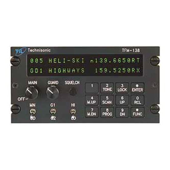
Page 13: Operator's Switches And Controls - Tfm-1 38A And 138B
FIGURE 2-2 Operator's Switches and Controls - TFM-138A and 138B... - Page 14 The transmit frequency is also shown. For the TFM-138A and TFM-138B (A "TX" (no TX tone/codes programmed) or "TT"(either TX tone or code programmed) on the right side of the display indicates whether the guard or main channel is active when transmitting.
-
Page 15: Programming Instructions
PROGRAMMING INSTRUCTIONS To program one of the 120 memory channels in the TFM-138A or 138 B, or one of the 25 memory channels in the TFM-138: Press the FUNC key. The display will show the function prompt. Press the PROG key. The display will show the current receive frequency with a flashing curser on the second digit (The first digit is always a one <1>). -
Page 16: Scanning Function
Selective memory scanning allows the user to select which of the 25 (in the TFM-138) or 120 (In the TFM-138A or 138B) memory channels are to be scanned or locked out when the scan function is invoked. To use this feature, follow the PROGRAMMING INSTRUCTIONS found in paragraph 2.3. -
Page 17: Receive Frequency Simplex Function
To exit this mode, recall one of the 25 (in the TFM-138) memory channels (ie. RCL,0,1) or 120 (in the TFM-138A and 138B) memory channels (ie. RCL, 0,0,1). Variable frequency mode is disabled when the internal entry disable jumper is set. -
Page 18: Programming Ctcss Tones
2.13 PROGRAMMING CTCSS TONES/DPL CODES NOTE: The TFM-138 supports only CTCSS tone functions. The TFM-138A and 138B support both CTCSS tone and DPL code functions. CTCSS tones (PL tones) or Digital DPL codes can be assigned to each memory channel. The guard receiver squelch will operate only on carrier detection, but guard 1 and 2 transmit tones or codes can be programmed. -
Page 19: Pc Memory/Programming Download Capability
The following paragraphs apply to the TFM-138A and TFM-138B only. The display will now show "RX DPL:" and the current 3-digit DPL code. If no DPL code is required "000" should be entered. Please note that if a DPL code is to be programmed a CTCSS tone should not be enabled. - Page 20 Insert the floppy disk into drive A and type: A:INSTALL <enter> All the files will be copied to your hard drive into a directory called \PCDL for TFM- 138 or \PCDLA for TFM-138A or \PCDLB for TFM-138B. Connections: With the PC turned off, plug the 25 pin male 'D' connector into its printer port.
- Page 21 Downloading to the Transceiver: Select 'D' from the main menu. Follow on screen instructions. The memory channels will be downloaded sequentially to the TFM-138 Series unit. You will be able to see them on the radio's display as they go by. The download process will take several minutes. (The data transfer is fast but the nonvolatile memory in the radio needs time to program.) The PC will return to the main menu when the process is complete.
- Page 22 944032A FIGURE 2-2 TFM-138B Transceiver PC Download Cable - wiring diagram 2-12...
-
Page 23: General
One 15 pin Cannon D mating connector (female) complete with crimp pins and hood. One BNC antenna mating RF connector (male) and hood. ANTENNA INSTALLATION Antenna, P/N AT-150 may be obtained from Technisonic Industries Limited or a suitable equivalent may be utilized with the TFM-138 Series transceivers. The antenna should be mounted on the bottom of the aircraft whenever possible. - Page 24 FIGURE 3-1 Outline Drawing for Model TFM-138 Series Transceivers...
-
Page 25: Wiring Instructions
INSTALLATION - PIN LOCATIONS AND CONNECTIONS (continued) TFM-138 Series Transceivers 15-Pin D Connections Pin # Description 600 Ohm Output Data Output Panel Lighting (28VDC or 5VAC) Memory UP/PC Download Input Memory Down/PC Download Input Mic Signal Input Main Power +28VDC Main Ground 4 ohm Speaker Output 4 ohm/600 ohm Output Ground... -
Page 27: Front Panel Back Lighting
3.7.4 Front Panel Back Lighting Front panel back lighting connection should be made on pin 3 of the transceiver. The opposite end of this lead should be connected to the panel lighting system of the aircraft. Before connecting, verify the required panel lighting voltage (28 VDC or 5VAC) on the transceiver configuration control label. - Page 28 Microprocessor Control Unit (MCU) PCB Module Notes: R23 is High Power Adjustment R24 is Low Power Adjustment J15 Jumper between pins 3 and 4 for Entry Enable Remove for Entry Disable FIGURE 3-3 Internal Enable/Disable Jumper and Transmit High/Low Power Adjust Locations...
-
Page 29: Transmitter Power Adjustments
TRANSMITTER POWER ADJUSTMENTS The transmitter power is adjusted to a maximum of 10 watts in high power mode and 1 watt in low power mode over the transceiver operating bandwith at the factory. If transmitter RF power re-adjustment is required, perform as follows: Remove bottom cover as described in the previous paragraph (3.8). - Page 30 FIGURE 3-4 Microphone and Sidetone Level, Main and Guard Squelch Adjustment Access Holes...
-
Page 31: Main And Guard Squelch Adjustments
3.12 MAIN AND GUARD SQUELCH ADJUSTMENT The squelch on both the main and guard receivers is factory set to open at approximately 0.5 microvolts. This adjustment can be made or altered to suit local conditions as follows: Set the main receiver of the transceiver to 156.000 MHz. Connect a signal generator to the the antenna input of the transceiver. - Page 32 Main Receiver/Transmitter PCB Module Notes: R30 is for 5.0 KHz (wideband) Deviation Adjustment R76 is for 2.5 KHz (narrowband) Deviation Adjustment (Narrowband adjustment applicable to TFM-138B only) FIGURE 3-5 Deviation Adjustment Potentiometer Location 3-10...
-
Page 33: Post Installation Emi Test
APPENDIX TO “INSTALLATION INSTRUCTIONS” POST INSTALLATION EMI TEST PURPOSE The purpose of this test is to identify any interference that the TFM-138, TFM-138A or TFM- 138B may cause with existing aircraft systems. For simplicity all TFM-138 model variations will be referred as TFM-138 series transceivers in this document. - Page 34 PROCEDURE Operate the TFM-138 series transmitter on the following frequencies for at least 20 seconds. Observe the GPS for any degradation in satellite status or availability or flags. FREQUENCIES GPS #1 GPS #2 TFM 138 PASS FAIL PASS FAIL 143.180 MHZ 143.1825 MHZ 157.5000 MHZ 157.5425 MHZ...
- Page 35 Determine if the image frequency for the VHF Comm falls within the range of the TFM-138 series unit. If so, select a set of frequencies that will cause the TFM-138 series unit to be set as close as possible to the image frequency. Any one of the many possible sets will suffice.
- Page 36 Determine if the image frequency for the VOR/ILS Nav falls within the range of the TFM-138 series unit. If so, select a two sets of frequencies that will cause the TFM- 138 series transceiver to be set as close as possible to the image frequency. Chose one set in the localizer frequency range, and one in the VOR frequency range.
- Page 37 Modulate the TFM-138 series transmitter on the following frequencies for at least 20 seconds. Look for any moment of flags or needles on the navigation display. FREQUENCIES RESULTS G/S #1 TFM-138 series PASS FAIL 334.7 (108.1) 167.3500 FREQUENCIES RESULTS G/S #1 TFM-138 series PASS FAIL...
- Page 38 NOTE: For the following tests, select a frequency at the top, middle and bottom of the range of the TFM -138 series transceiver. Frequency #1 ______________ Frequency #2 ______________ Frequency #3 ______________ At a safe altitude engage the autopilot or stability augmentation system. Modulate the TFM- 138 series transmitter on the above frequencies for at least 20 seconds.
- Page 39 List the power plant, fuel and other electric instruments in the chart provided and note any anomalies that occur while transmitting. Assess the results. STEP SYSTEM PASS FAIL NOTES Xponder & Encoder ADF 1 & 2 Compass Directional Gyro Oil Pressure Fuel Pressure Oil Temp Amps...
- Page 40 STEP SYSTEM PASS FAIL NOTES Fuel % Torque % Annunciators Digital Clock...
- Page 41 STEP SYSTEM PASS FAIL NOTES...
- Page 42 STEP SYSTEM PASS FAIL NOTES NOTES: A-10...
Need help?
Do you have a question about the TFM-138A and is the answer not in the manual?
Questions and answers