Technisonic Industries Limited TDFM-600 Series Maintenance Manual
Multiband p25 airborne transceiver
Hide thumbs
Also See for TDFM-600 Series:
- Installation and operating instructions manual (34 pages) ,
- Installation and operating instructions manual (23 pages)
Table of Contents
Advertisement
Quick Links
TDFM-600/6000
MULTIBAND P25 AIRBORNE TRANSCEIVER
Maintenance Manual
TiL Document No. 06RE376
Revision B
MARCH 2021
Technisonic Industries Limited
240 Traders Boulevard, Mississauga, Ontario L4Z 1W7
Tel: (905) 890-2113 Fax: (905) 890-5338
www.til.ca
Copyright by Technisonic Industries Limited. All rights reserved.
Advertisement
Table of Contents

Related Manuals for Technisonic Industries Limited TDFM-600 Series


Summary of Contents for Technisonic Industries Limited TDFM-600 Series
- Page 1 TDFM-600/6000 MULTIBAND P25 AIRBORNE TRANSCEIVER Maintenance Manual TiL Document No. 06RE376 Revision B MARCH 2021 Technisonic Industries Limited 240 Traders Boulevard, Mississauga, Ontario L4Z 1W7 Tel: (905) 890-2113 Fax: (905) 890-5338 www.til.ca Copyright by Technisonic Industries Limited. All rights reserved.
- Page 3 REVISION HISTORY [ 06RE376 ] SECTION EDITED DESCRIPTION DATE PAGE Original Issue JUN 2009 F.M. Global New Document template, Title Page layout changed Rev History page “edited by” column added Document split, Sections 5 to 8 now 1 to 5 4-A1 Updated MCU Block Diagram to Rev A (CR#09877) Sect 4&5...
- Page 5 Information and Service Bulletins” and the software/firmware history index ( Getting Help For assistance with any of the Technisonic products, contact Technisonic Customer Product Service: Technisonic Industries Limited 240 Traders Boulevard Mississauga, Ontario L4Z 1W7 Phone: - 905-890-2113...
- Page 6 WARRANTY INFORMATION The Model TDFM-600/6000 Transceiver is under warranty for one year from date of purchase. Failed units caused by defective parts, or workmanship should be returned to: Technisonic Industries Limited 240 Traders Boulevard Mississauga, Ontario L4Z 1W7 Tel: (905) 890-2113...
-
Page 7: Table Of Contents
TECHNISONIC INDUSTRIES LIMITED www.til.ca TABLE OF CONTENTS Section Title Page SECTION 1 THEORY OF OPERATION INTRODUCTION ........................1-1 1.1.1 TDFM-600/6000 Series Overview ..................1-1 1.1.2 Transceiver Models TDFM-600/6000 Series Type I ............1-3 1.1.3 Transceiver Models TDFM-600/6000 Series Type II ............1-4 1.1.3... - Page 8 TECHNISONIC INDUSTRIES LIMITED www.til.ca Section Title Page SECTION 3 FACTORY TEST PROCEDURES FACTORY TEST PROCEDURES ..................3-1 TEST PROCEDURE REQUIREMENTS ................3-1 3.1.1 Equipment Required ......................3-1 3.1.2 Documentation Required ....................3-1 PRODUCTION TEST SEQUENCE ..................3-2 SECTION 4 SCHEMATICS and LAYOUTS INTRODUCTION ........................
- Page 9 TECHNISONIC INDUSTRIES LIMITED www.til.ca LIST OF FIGURES Figure Title Page Typical TDFM-600/6000 Transceiver ................Functional Similarities of a Typical Portable Radio and the TDFM-600/6000 ....TDFM-600/6000 Transceiver - Internal Modules ............. The TDFM-600/6000 System Architecture ............... 1-10 1.5a TDFM-600/6000 Module A1 - The Microcontroller (MCU) Board ........1-11 1.5b...
- Page 10 TECHNISONIC INDUSTRIES LIMITED www.til.ca TYPE II TDFM-600/6000 Transceiver – Exploded View ..............2-20 2.4.1A Heatsink Fan Mounting Screws ..................2-21 2.4.1B Heatsink 2-Pin Fan Connector Removed ................. 2-21 2.4.2A Screws Securing the Top Cover ..................2-22 2.4.2B Screws Securing the Bottom Cover ................. 2-22 2.4.2C...
- Page 11 TECHNISONIC INDUSTRIES LIMITED www.til.ca LIST OF TABLES Table Title Page TDFM-600/6000 SERIES TYPE I Transceiver – Configuration Overview ......1-8 TDFM-600/6000 SERIES TYPE II Transceiver – Configuration Overview ....... 1-9 MCU Sockets, Jumpers and Connectors ................1-12 MIC Level Adjust, Side Tone Adjust and RX Audio ............1-12 Sample of Type I Transceiver Label ..................
- Page 12 TECHNISONIC INDUSTRIES LIMITED www.til.ca LIST OF FUNCTIONAL, SCHEMATIC AND COMPONMENT LAYOUT DIAGRAMS Figure No. Title Section TDFM-600/6000 Transceiver - Exploded View of Modules 012701 ....... 4-A TDFM-600/6000 Transceiver - System Block Diagram 014803 ........4-A A1 MODULE MICROCONTROLLER (MCU) SECTION P/N 013500-1 A1 Module Microcontroller (MCU) - Block Functional Diagram 014084A ....
- Page 13 TECHNISONIC INDUSTRIES LIMITED www.til.ca A2(I) MODULE INTERFACE BOARD, DUAL MODULE SECTION P/N 013510-1 4.2.1 A2(I) Interface, Dual module - Schematic Diagram, Rev D ..........4-A2 4.2.1 A2(I) Interface, Dual module - Schematic Diagram, Rev B ..........4-A2 4.2.1 A2(I) Interface, Dual module - Schematic Diagram, ............4-A2 4.2.1a...
- Page 14 TECHNISONIC INDUSTRIES LIMITED www.til.ca TDFM-600 FRONT PANEL and TDFM-6000 FRONT PANEL A4 FRONT PANEL ASSEMBLY 4.4.0 A4 Module Front Panel - Functional Block Diagram 014085 ...........4-A4 A4 Front Panel Board 4.4.1.1 A4 Front Panel Board 28v PN 003496-1,-2 - Schematic Diagram, Rev C .......4-A4 4.4.1.1...
-
Page 15: Theory Of Operation
TECHNISONIC INDUSTRIES LIMITED www.til.ca SECTION 1 – THEORY OF OPERATION INTRODUCTION TDFM-600/6000 series Type I transceivers have Part Numbers 011210-1 and 011210-2. TDFM-600/6000 series Type II transceivers have Part Numbers 011210-3 and 011210-4. The "-1,3" configuration denotes a green LED-matrix display, while the "-2,4" configuration denotes a red LED-matrix display. - Page 16 Each TDFM-600/6000 series radio may contain one, two or three separate RF band modules. The TDFM-600 series may have one or two bands installed and the TDFM-6000 will have three band modules installed. The TDFM-600 and 6000 series radios are designed to have different combinations of RF modules installed as required by the end user.
-
Page 17: Transceiver Models Tdfm-600/6000 Series Type I
Simulcast, the optional AMS-6000 mode selector should be used in conjunction with the TDFM-600/6000 series transceivers. TDFM-600 series transceivers support dual band operation in two of the following bands: VHF (136 to 174 MHz) UHF Lo (403 to 470 MHz) - Page 18 TECHNISONIC INDUSTRIES LIMITED www.til.ca 1.1.2 Transceiver Models TDFM-600/6000 Series Type II The TDFM-600/6000 Type II series of transceivers offer the most up-to-date, maximum performance technology including P25 CAI, P25 Trunking and AES with P25 OTAR. Note: Some features are extra cost options. Supports up to three bands (TDFM-6000) or two bands (TDFM-600) customized to your requirement.
-
Page 19: Programming
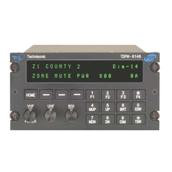
TECHNISONIC INDUSTRIES LIMITED www.til.ca 1.1.3 Programming The TDFM-600/6000 transceivers must be programmed with Motorola CPS software. Additional options can be ordered to support operation within existing Motorola radio systems. Contact Technisonic sales department for further information. If you are familiar with the Motorola portable radio (XTS 3000), then this picture will show the similarities that exist with the TDFM-600/6000 front panel. -
Page 20: Tdfm-600/6000 Models
TECHNISONIC INDUSTRIES LIMITED www.til.ca 1.1.4 TDFM-600/6000 Models The TDFM-600/6000 Models contain four modules which are housed in a single chassis (see Figure 1.3). These modules and their sub-modules are described in the following paragraphs (Schematics and Layouts are also referenced, see Section 4):... - Page 21 TECHNISONIC INDUSTRIES LIMITED www.til.ca FIGURE 1.3 TDFM-600/6000 Transceiver - Internal Modules TDFM-600/6000 Maintenance Manual TiL 06RE376B...
- Page 22 TECHNISONIC INDUSTRIES LIMITED www.til.ca TDFM-600/6000 (P/N 011210-1,-2) CONFIGURATION OVERVIEW SERIES TYPE I A1 MCU ASSEMBLY MCU Board - P/N 013500-1 Power Module Board - P/N 013511-1 [NFS] A2(I) INTERFACE BOARD Interface Board, Dual Module – P/N 013510-1 A3(I) INTERFACE BOARD Interface Board, Single Module –...
- Page 23 TECHNISONIC INDUSTRIES LIMITED www.til.ca TDFM-600/6000 (P/N 011210-3,-4) CONFIGURATION OVERVIEW SERIES TYPE II A1 MCU ASSEMBLY MCU Board - P/N 013500-1 Power Module Board - P/N 013511-1 Uses XTS-5000 Modules or Combination of XTS-3000 and XTS-5000 Modules A2(II) INTERFACE BOARD Interface Board, XTS-5000 Dual – P/N 033596-1 A2A(II) HYBRID INTERFACE BOARD Interface Board, XTS-3000/ XTS-5000 Dual –...
-
Page 24: System Overview
TECHNISONIC INDUSTRIES LIMITED www.til.ca 1.1.5 System Overview The TDFM-600/6000 transceiver is divided into five physical functional blocks. These divisions are shown in the block diagram of Figure 1.4 below. Note that the schematic diagrams for each module are provided in section 4. The theory of operation will refer to these schematics, as well as to the block diagrams given in this section. - Page 25 TECHNISONIC INDUSTRIES LIMITED www.til.ca MODULE A1, MICROCONTROLLER (MCU) BOARD (Continued) FIGURE 1.5a TDFM-600/6000 Module A1 - The Microcontroller (MCU) Board TDFM-600/6000 Maintenance Manual TIL 06RE37B 1-11...
- Page 26 TECHNISONIC INDUSTRIES LIMITED www.til.ca FIGURE 1.5b TDFM-600/6000 Module A1 – Audio Section TDFM-600/6000 Maintenance Manual TIL 06RE37B 1-12...
- Page 27 TECHNISONIC INDUSTRIES LIMITED www.til.ca MODULE A1, MICROCONTROLLER (MCU) BOARD (Continued) MCU Connectors 25-pin connector at rear of MCU (transceiver) 2-pin connector for the external heatsink fan 26-pin connector for the interface cards (MCU top) BANDS 1 and 2 4-wire connection for power module to Band 2...
-
Page 28: The Mcu-Input Filter And Protection
TECHNISONIC INDUSTRIES LIMITED www.til.ca The MCU-Input Filter and Protection The PTT (push-to-talk) 1,2,3 and M.UP, M.DN (of J1 pin 5,7,10,16, and 17) pass through input filter and protection circuits to access the MCU (U1). 1.2.2 The MCU-Audio Section The audio processor handles all audio to, from, and generated within the TDFM-600/6000. -
Page 29: Module A2 (Type I), A3 (Type I) Interface Board
TECHNISONIC INDUSTRIES LIMITED www.til.ca MODULE A2 (TYPE I), A3 (TYPE I) INTERFACE BOARD Interface Board, dual module A2 (Type I), P/N 013510-1 Interface Board, single module A3 (Type I), P/N 013509-1 Refer to: Interface Board, Schematic Diagram, Figure 4.2.1 Interface Board, Component Layout Diagram, Figure 4.2.1a 1.3.1... -
Page 30: Module A4, Front Panel Assembly
TECHNISONIC INDUSTRIES LIMITED www.til.ca MODULE A4, FRONT PANEL ASSEMBLY The front panel assembly can be divided into 3 main parts: 1. the Front Panel (Keypad) board 2. the Display board 3. the Interconnect board Series 600 Series 6000 Front Panel Assembly 28v (Green) -
Page 31: Module A4 - The Front Panel Assembly
TECHNISONIC INDUSTRIES LIMITED www.til.ca MODULE A4, FRONT PANEL (Continued) Note: E3 - Not used on TDFM 600 FIGURE 1.6 Front Panel Assembly Block Diagram 1.4.1 Module A4 – The Front Panel Assembly The Front Panel assembly consists of three sub-assemblies: the front panel interface board, the display board and the keypad board. -
Page 32: Module A4 - Front Panel Display Board
TECHNISONIC INDUSTRIES LIMITED www.til.ca MODULE A4, FRONT PANEL (Continued) 1.4.2 Module A4 – Front Panel Display Board The front panel display board includes three (3) alpha-numeric LED display modules (DISP1, DISP2, and DISP3). Each module has 2x8 characters for a total of 2x24 characters. -
Page 33: Troubleshooting And Module Replacement
TECHNISONIC INDUSTRIES LIMITED www.til.ca SECTION 2 – TROUBLESHOOTING AND MODULE REPLACEMENT INTRODUCTION This section describes the procedure for trouble shooting and module replacement for the Technisonic TDFM-600/6000 Series Type I and Type II. ISOLATING PROBLEMS TO MODULES TYPE I As seen in section 1, the TDFM-600/6000 is broken into four (4) modules (assemblies) internally (see Figure 2.1), these modules are combined to create a complete unit. - Page 34 TECHNISONIC INDUSTRIES LIMITED www.til.ca MODULE REPLACEMENT PROCEDURE – Type I continued The next following sections describe the disassembly procedure step-by-step. NOTE: Module designation (e.g. A1 through A4) may not be a factual name applied to a module, but it is placed there for easier referencing and identification to help locate and ID parts.
-
Page 35: Removing The Heatsink
TECHNISONIC INDUSTRIES LIMITED www.til.ca MODULE REPLACEMENT PROCEDURE – Type I continued 2.2.1 Removing the Heatsink Fan Remove the three (3) screws that secure the fan to the posts mounted on the back of the heatsink. See Figure 2.2.1A. This will expose a heatsink mounting screw after removing the fan. - Page 36 TECHNISONIC INDUSTRIES LIMITED www.til.ca MODULE REPLACEMENT PROCEDURE – Type I continued 2.2.2 Removing the Top and Bottom Covers Remove all the screws holding the top and bottom covers. Begin with the 4 mounting screws located on the top side (labeled 4 through 7), then the 3 mounting screws located on the top (labeled 1*, 2, and 3).
- Page 37 TECHNISONIC INDUSTRIES LIMITED www.til.ca MODULE REPLACEMENT PROCEDURE – Type I continued View with the top and bottom covers removed. See Figure 2.2.2C. FIGURE 2.2.2C The Top and Bottom Covers Removed 2.2.3 Removing the Heatsink Mounting Screws There are five (5) or six (6) black oxide screws mounted that secure the heatsink to the chassis depending on the age of the radio (Type I or Type II).
- Page 38 TECHNISONIC INDUSTRIES LIMITED www.til.ca MODULE REPLACEMENT PROCEDURE – Type I continued 2.2.4 Detaching the Heatsink Remove the 2 hex standoff screws from the 25-pin male DB-connector with a ¼ inch socket. See Figure 2.2.4A (labeled as A and B). FIGURE 2.2.4A The Heatsink 25-Pin Male DB-Connector Remove the 4 flush mount screws on the sides of the heat sink.
- Page 39 TECHNISONIC INDUSTRIES LIMITED www.til.ca MODULE REPLACEMENT PROCEDURE – Type I continued Gently pull the heat sink away from the radio chassis as there are 2 or 3 mini-coax attached. See Figure 2.2.4C. FIGURE 2.2.4C Heatsink Pulled Away from the Chassis With a pair of needle nose pliers, grab the neck of the mini-coax connector on the RF module and gently twist up and away from the module.
- Page 40 TECHNISONIC INDUSTRIES LIMITED www.til.ca MODULE REPLACEMENT PROCEDURE – Type I continued Heat sink detached from the radio transceiver. See Figure 2.2.4E. FIGURE 2.2.4E Heatsink Removed from Chassis TDFM-600/6000 Maintenance Manual TiL 06RE376B...
- Page 41 TECHNISONIC INDUSTRIES LIMITED www.til.ca MODULE REPLACEMENT PROCEDURE – Type I continued 2.2.5 Removing Module A2 – Interface Board, Dual module Remove the two (2) screws holding the top Interface Board, Dual module. Pop the interface board off of each module and pull it out of the chassis. See Figure 2.2.5A.
- Page 42 TECHNISONIC INDUSTRIES LIMITED www.til.ca MODULE REPLACEMENT PROCEDURE – Type I continued 2.2.6 Removing Module A3 – Interface Board Single module (Optional) If the radio has 3 bands, then flip chassis over and remove the two (2) screws on bottom single interface board. See Figure 2.2.6A.
- Page 43 TECHNISONIC INDUSTRIES LIMITED www.til.ca MODULE REPLACEMENT PROCEDURE – Type I continued 2.2.7 Removing the Motorola Transceiver Module(s) Tray Remove the four (4) screws labeled A1. B1, C1, D1 securing the top tray to the chassis. See Figure 2.2.7A. FIGURE 2.2.7A Removing Transceiver Module(s) Tray (Top) Gently remove the transceiver modules tray away from the chassis.
- Page 44 TECHNISONIC INDUSTRIES LIMITED www.til.ca MODULE REPLACEMENT PROCEDURE – Type I continued 2.2.8 Removing Motorola Transceiver / MCU Module(s) Tray Remove the four (4) screws labeled A2, B2, C2, D2 securing the bottom tray holding the transceiver module and the MCU module. See Figure 2.2.7A. and Figure 2.2.8A.
- Page 45 TECHNISONIC INDUSTRIES LIMITED www.til.ca MODULE REPLACEMENT PROCEDURE – Type I continued FIGURE 2.2.8C Transceiver Module Tray Removed (top and bottom view) 2.2.9 Removing the MCU MODULE from tray Remove the 9 screws and washers holding MCU board from the bottom tray (7 into the board, 2 through the DB-15 connector body labeled 8 and 9 are longer).
- Page 46 TECHNISONIC INDUSTRIES LIMITED www.til.ca MODULE REPLACEMENT PROCEDURE – Type I continued 2.2.10 Transceiver module replacement To replace a transceiver module, just remove the 5 round-headed screws and lock washers that secure that particular module to the tray. See the tray bottom views in Figures 2.2.7.B and 2.2.10...
- Page 47 TECHNISONIC INDUSTRIES LIMITED www.til.ca MODULE REPLACEMENT PROCEDURE – Type I continued 2.2.12 Disassembling Module A4 – Front Panel Module For removal of the front knobs, use the Xcelite ® tool LN-21 (1/16”) or equivalent to loosen knobs from potentiometer shaft. See Figure 2.2.12A.
- Page 48 TECHNISONIC INDUSTRIES LIMITED www.til.ca MODULE REPLACEMENT PROCEDURE – Type I continued The keypad, display and interconnect board seen below in Figure 2.2.12C. Figure 2.2.12C The Keypad, Display and Interconnect Board Remove the 4 screws and the 4 split-washers securing the keypad board labeled A, B, C, and D as shown in Figure 2.2.12C.
- Page 49 TECHNISONIC INDUSTRIES LIMITED www.til.ca The display board is soldered to the interconnect board. To replace either, use the appropriate de-soldering tools for the job. FIGURE 2.2.12E The Display and Interconnect Board (top and bottom view) For unit re-assembly, just reverse the disassembly order to build the unit back up again.
- Page 50 TECHNISONIC INDUSTRIES LIMITED www.til.ca This page left intentionally blank. TDFM-600/6000 Maintenance Manual TiL 06RE376B 2-18...
- Page 51 TECHNISONIC INDUSTRIES LIMITED www.til.ca ISOLATING PROBLEMS TO MODULES TYPE II As seen in section 1, the TDFM-600/6000 is broken into four (4) modules (assemblies) internally (see figure 2.2), these modules are combined to create a complete unit. If the transceiver fails to operate correctly, the repair philosophy is to isolate the problem to one of the modules.
- Page 52 TECHNISONIC INDUSTRIES LIMITED www.til.ca MODULE REPLACEMENT PROCEDURE – Type II continued The next following sections describe the disassembly procedure step-by-step. Module designation (e.g. A1 through A4) may not be a factual name applied to NOTE: a module, but it is placed there for easier referencing and identification to help locate and ID parts.
- Page 53 TECHNISONIC INDUSTRIES LIMITED www.til.ca MODULE REPLACEMENT PROCEDURE – Type II continued 2.4.1 Removing the Heatsink Fan Remove the three (3) screws that secure the fan to the posts mounted on the back of the heatsink. See figure 2.4.1A. This will expose a heatsink mounting screw after removing the fan.
- Page 54 TECHNISONIC INDUSTRIES LIMITED www.til.ca MODULE REPLACEMENT PROCEDURE – Type II continued 2.4.2 Removing the Top and Bottom Covers Remove all the screws holding the top and bottom covers. Begin with the 4 mounting screws located on the top side (labeled 4 through 7), then the 3 mounting screws located on the top (labeled 1*, 2, and 3).
- Page 55 TECHNISONIC INDUSTRIES LIMITED www.til.ca MODULE REPLACEMENT PROCEDURE – Type II continued View with the top and bottom covers removed. See Figure 2.4.2C. FIGURE 2.4.2C The Top and Bottom Covers Removed 2.4.3 Removing the Heatsink Mounting Screws There are five (5) or six (6) black oxide screws mounted that secure the heatsink to the chassis depending on the age of the radio (Type I or Type II).
- Page 56 TECHNISONIC INDUSTRIES LIMITED www.til.ca MODULE REPLACEMENT PROCEDURE – Type II continued 2.4.4 Detaching the Heatsink Remove the 2 hex standoff screws from the 25-pin male DB-connector with a ¼ inch socket. See Figure 2.4.4A (labeled as A and B). FIGURE 2.4.4A The Heatsink 25-Pin Male DB-Connector Remove the 4 flush mount screws on the sides of the heat sink.
- Page 57 TECHNISONIC INDUSTRIES LIMITED www.til.ca MODULE REPLACEMENT PROCEDURE – Type II continued Gently pull the heat sink away from the radio chassis as there are 2 or 3 mini-coax attached. See Figure 2.4.4C. FIGURE 2.2.4C Heatsink Pulled Away from the Chassis With a pair of needle nose pliers, grab the neck of the mini-coax connector on the RF module and gently twist up and away from the module.
- Page 58 TECHNISONIC INDUSTRIES LIMITED www.til.ca MODULE REPLACEMENT PROCEDURE – Type II continued Heat sink detached from the radio transceiver. See Figure 2.4.4E. FIGURE 2.4.4E Heatsink Removed from Chassis TDFM-600/6000 Maintenance Manual TiL 06RE376B 2-26...
- Page 59 TECHNISONIC INDUSTRIES LIMITED www.til.ca MODULE REPLACEMENT PROCEDURE – Type II continued 2.4.5 Removing Module A2 – Interface Board, Dual module Remove the two (2) screws holding the top Interface Board, Dual module. Pop the interface board off of each module and pull it out of the chassis. See Figure 2.4.5A.
- Page 60 TECHNISONIC INDUSTRIES LIMITED www.til.ca MODULE REPLACEMENT PROCEDURE – Type II continued 2.4.6 Removing Module A3 – Interface Board Single Module (Optional) If the radio has 3 bands, then flip chassis over and remove the two (2) screws on bottom single interface board. See Figure 2.4.6A.
- Page 61 TECHNISONIC INDUSTRIES LIMITED www.til.ca MODULE REPLACEMENT PROCEDURE – Type II continued 2.4.7 Removing the Motorola Transceiver Module(s) Tray Remove the four (4) screws labeled A1. B1, C1, D1 securing the top tray to the chassis. See Figure 2.4.7A. FIGURE 2.4.7A Removing Transceiver Module(s) Tray (Top) Gently remove the transceiver modules tray away from the chassis.
- Page 62 TECHNISONIC INDUSTRIES LIMITED www.til.ca MODULE REPLACEMENT PROCEDURE – Type II continued 2.4.8 Removing Motorola Transceiver / MCU Module(s) Tray Remove the four (4) screws labeled A2, B2, C2, D2 securing the bottom tray holding the transceiver module and the MCU module. See Figure 2.4.7A. and/or Figure 2.4.8A.
- Page 63 TECHNISONIC INDUSTRIES LIMITED www.til.ca MODULE REPLACEMENT PROCEDURE – Type II continued FIGURE 2.4.8C Transceiver Module Tray Removed (top and bottom view) 2.4.9 Removing the MCU MODULE from tray Remove the 9 screws and washers holding MCU board from the bottom tray (7 into the board, 2 through the DB-15 connector body labeled 8 and 9 are longer).
- Page 64 TECHNISONIC INDUSTRIES LIMITED www.til.ca MODULE REPLACEMENT PROCEDURE – Type II continued 2.4.10 Transceiver module replacement Note that the Type II transceiver modules cane be removed without disassembling the tray. Example module: Remove the two (2) screws holding the side bracket labeled that attaches the transceivers in both trays to the side of the chassis.
- Page 65 TECHNISONIC INDUSTRIES LIMITED www.til.ca 2.4.11 Removing Side Panels from Front Panel Module Remove the (4) screws labeled A through D. Remove the (4) screws labeled 1 through 4. FIGURE 2.4.11 Removal of the Side Panels from the Front Panel Assembly MODULE REPLACEMENT PROCEDURE –...
- Page 66 TECHNISONIC INDUSTRIES LIMITED www.til.ca Next remove the three (3) hex nuts (13/32) and washers from the potentiometer shafts in Figure 2.4.12B. Now you can remove the front panel chassis plate. See Figure 2.4.12B. FIGURE 2.4.12B Removal of the Front Face Plate and Front Panel Chassis Plate...
- Page 67 TECHNISONIC INDUSTRIES LIMITED www.til.ca MODULE REPLACEMENT PROCEDURE – Type II continued The keypad, display and interconnect board seen below in Figure 2.4.12C. Figure 2.4.12C The Keypad, Display and Interconnect board Remove the 4 screws and the 4 split-washers securing the keypad board labeled A, B, C, and D as shown in Figure 2.4.12D.
- Page 68 TECHNISONIC INDUSTRIES LIMITED www.til.ca MODULE REPLACEMENT PROCEDURE – Type II continued The display board is soldered to the interconnect board. To replace either, use the appropriate de-soldering tools for the job. FIGURE 2.4.12E The Display and Interconnect board (top and bottom view) For unit re-assembly, just reverse the disassembly order to build the unit back up again.
- Page 69 TECHNISONIC INDUSTRIES LIMITED www.til.ca ISOLATING PROBLEMS TO MODULES TYPE II (HYBRID) As seen in section 1, the TDFM-600/6000 is broken into four (4) modules (assemblies) internally (see figure 2.1), these modules are combined to create a complete unit. If the transceiver fails to operate correctly, the repair philosophy is to isolate the problem to one of the modules.
- Page 70 TECHNISONIC INDUSTRIES LIMITED www.til.ca MODULE REPLACEMENT PROCEDURE – Type II HYBRID continued The next following sections describe the disassembly procedure step-by-step. Module designation (e.g. A1 through A4) may not be a factual name applied to NOTE: a module, but it is placed there for easier referencing and identification to help locate and ID parts.
- Page 71 TECHNISONIC INDUSTRIES LIMITED www.til.ca 2.6.1 Identifying HYBRIDS A radio that has just (1) Type I module in a Type II radio is a hybrid. A radio can have any combination of bands, but just needs 1 or 2 Type I module(s) to make it a hybrid.
- Page 72 TECHNISONIC INDUSTRIES LIMITED www.til.ca MODULE REPLACEMENT PROCEDURE – Type II continued Removing the Interface Board, Dual Module 26-Pin Header: Remove the 26-pin header with small pliers. Just pull it out. See Figure 2.6.2B. Note: Place the 26-pin header into this...
-
Page 73: Post Repair Testing
TECHNISONIC INDUSTRIES LIMITED www.til.ca POST REPAIR TESTING After any service is performed on the TDFM-600/6000, you should perform a final test to ensure that the unit is operating within the specified parameters. If the unit does not operate according to these parameters, then the appropriate alignment procedures (if any) should be consulted. - Page 74 TECHNISONIC INDUSTRIES LIMITED www.til.ca This page left intentionally blank. TDFM-600/6000 Maintenance Manual TiL 06RE376B 2-42...
-
Page 75: Factory Test Procedures
TECHNISONIC INDUSTRIES LIMITED www.til.ca SECTION 3 - ALIGNMENT PROCEDURES FOR TDFM-600/6000 TRANSCEIVERS FACTORY TEST PROCEDURES This section provides information about the factory Alignment and Test procedures. All the test procedures are included in the Appendices of this document. See table below. -
Page 76: Production Test Sequence
TECHNISONIC INDUSTRIES LIMITED www.til.ca PRODUCTION TEST SEQUENCE The flow chart of figure 3.1 shows the test sequence for the UUT after manufacturing. Perform the Final Test after replacing any modules in the radio. FIGURE 3.1 Production Test Sequence TDFM-600/6000 Maintenance Manual... -
Page 77: Introduction
TECHNISONIC INDUSTRIES LIMITED www.til.ca SECTION 4 - SCHEMATICS INTRODUCTION This section contains a complete set of block diagrams, schematic diagrams and component layout (artwork) diagrams for the TDFM-600/6000 Transceiver. Schematic diagrams are foldout illustrations. The TDFM-600/6000 Motorola modules uses P/N 027325 and P/N 047353 (see section 2). - Page 78 TECHNISONIC INDUSTRIES LIMITED www.til.ca FIGURE 4.1 Exploded View of TDFM-600/6000 Transceiver - Internal Modules TDFM-600/6000 Maintenance Manual TiL 06RE376B...
- Page 79 TECHNISONIC INDUSTRIES LIMITED www.til.ca TDFM-600/6000 (P/N 011210-1,-2) CONFIGURATION OVERVIEW SERIES TYPE I A1 MCU ASSEMBLY MCU Board - P/N 013500-1 Power Module Board - P/N 013511-1 [NFS] A2(I) INTERFACE BOARD Interface Board, Dual Module – P/N 013510-1 A3(I) INTERFACE BOARD Interface Board, Single Module –...
- Page 80 TECHNISONIC INDUSTRIES LIMITED www.til.ca TDFM-600/6000 (P/N 011210-3,-4) CONFIGURATION OVERVIEW SERIES TYPE II A1 MCU ASSEMBLY MCU Board - P/N 013500-1 Power Module Board - P/N 013511-1 A2(II) INTERFACE BOARD Interface Board, XTS-5000 Dual – P/N 033596-1 A2A(II) HYBRID INTERFACE BOARD Interface Board, XTS-3000/ XTS-5000 Dual –...
-
Page 81: Drawing Index
TECHNISONIC INDUSTRIES LIMITED www.til.ca DRAWING INDEX TABLE 4.2 REFERENCE TABLE SCHEMATICS and COMPONENT LAYOUT SECTIONED by MODULES TDFM-600/6000 Series Type I and II - Transceiver Final Assembly Assembly Display Parts List 011210-1,-2 Grn, Red TDFM-600/6000 Series Type I 012722-1lL,-2L Page 5-11,16... - Page 82 TECHNISONIC INDUSTRIES LIMITED www.til.ca A1 MODULE - MICROCONTROLLER (MCU) SECTION (P/N) 013500-1 Block Diagram 014804A Fig. 4.1 Series Parts List P/N-x Type Figure Schematic Figure Layout Page 5-35 Start 015431N 019196M 012668-1AJ 013500-1 I&II 4.1.1 4.1.1a 015431M 019196L 012668-1AH 013500-1 I&II...
- Page 83 TECHNISONIC INDUSTRIES LIMITED www.til.ca A2(I) MODULE INTERFACE BOARD, DUAL MODULE (P/N) 013510-1 Series Parts List Type Figure Schematic Figure Layout Page 5-45 Start 013510-1 4.2.1 015445D 4.2.1a 019211B 012682-1D 013510-1 4.2.1 015445D 4.2.1a 019211B 012682C 013510-1 4.2.1 015445B 4.2.1a 019211B...
- Page 84 TECHNISONIC INDUSTRIES LIMITED www.til.ca A2B(II) HYBRID INTERFACE BOARD, XTS-5000/XTS-3000 DUAL MODULE (P/N) 043601-1 Series Parts List Type Figure Schematic Figure Layout Page 5-50 Start 043601-1 4.3.4 045512C 4.3.4a 049479B 042803-1G 043601-1 4.3.4 045512C 4.3.4a 049479B 042803F 043601-1 4.3.4 045512A 4.3.4a...
- Page 85 TECHNISONIC INDUSTRIES LIMITED www.til.ca A4A1 FRONT PANEL BOARD (P/N) 003496-1 [28v and 28v NV new] Figure Schematic Figure Layout Parts List Page SN Start 003496-1 4.4.1.1 005427C 4.4.1.1a 009183D 012697-1J 5-57 003496-1 4.4.1.1 005427C 4.4.1.1a 009183D 012697-1H 003496-1 4.4.1.1 005427C 4.4.1.1a...
- Page 86 TECHNISONIC INDUSTRIES LIMITED www.til.ca TDFM 6000 SERIES TYPE II A4 FRONT PANEL ASSEMBLY CONFIGURATION SECTION Block Diagram 014085 Fig. 4.4.0 Configuration Display Display 013535 Green Parts List Page SN Start SN End 013535-1 012711-1E 5-67 013535-2 012711-2E 5-68 013535-1,2 012711D...
- Page 87 TECHNISONIC INDUSTRIES LIMITED www.til.ca A4 FRONT PANEL BOARD (P/N) 003496-2 [28v and 28v NV new] Figure Schematic Figure Layout Parts List Page SN Start 003496-2 4.4.1.1 005427C 4.4.1.1a 009183D 012697-2J 5-73 003496-2 4.4.1.1 005427C 4.4.1.1a 009183D 012697-2H 003496-2 4.4.1.1 005427C 4.4.1.1a...
-
Page 88: Diagrams Sectioned By Modules
5V Green, Red 5V Green, Red 28V NV 28V NV 5V NV 5V NV Common to both TDFM-600 Series Type I and TDFM-6000 Series Type II A4A2 - Display Board A4A3 - Interface Board TDFM-600/6000 Maintenance Manual TiL 06RE376B 4-12... - Page 89 Figure 4 TDFM-600/6000 Transceiver - Exploded View of Modules 4 – A...
- Page 90 Figure 4.0 TDFM-600/6000 Transceiver – Block Diagram 4 – A...
- Page 91 MCU MODULE (A1)
- Page 92 Figure 4.1 Micro controller (MCU) Board Module A1 - Block Diagram (Rev. A) 4 – A1...
- Page 93 Figure 4.1.1 Microcontroller (MCU) Board Module A1 - Schematic Diagram (Rev. N) 4 – A1...
- Page 94 Figure 4.1.1 Microcontroller (MCU) Board Module A1 - Schematic Diagram (Rev. M) 4 – A1...
- Page 95 Figure 4.1.1 Microcontroller (MCU) Board Module A1 - Schematic Diagram (Rev. L) 4 – A1...
- Page 96 Figure 4.1.1 Microcontroller (MCU) Board Module A1 - Schematic Diagram (Rev. K) 4 – A1...
- Page 97 Figure 4.1.1 Microcontroller (MCU) Board Module A1 - Schematic Diagram (Rev. J) 4 – A1...
- Page 98 Figure 4.1.1 Microcontroller (MCU) Board Module A1 - Schematic Diagram (Rev. H) 4 – A1...
- Page 99 Figure 4.1.1 Microcontroller (MCU) Board Module A1 - Schematic Diagram (Rev. G) 4 – A1...
- Page 100 Figure 4.1.1 Microcontroller (MCU) Board Module A1 - Schematic Diagram (Rev. F) 4 – A1...
- Page 101 Figure 4.1.1 Microcontroller (MCU) Board Module A1 - Schematic Diagram (Rev. D) 4 – A1...
- Page 102 Figure 4.1.1 Microcontroller (MCU) Board Module A1 - Schematic Diagram (Rev. C) 4 – A1...
- Page 103 Figure 4.1.1 Microcontroller (MCU) Board Module A1 - Schematic Diagram (Rev. B) 4 – A1...
- Page 104 TECHNISONIC INDUSTRIES LIMITED www.til.ca Top Silk Screen Figure 4.1.1a Microcontroller (MCU) Module A1 - Component Layout, ASSY # 013500-1 LAYOUT 019196 (Rev. M), (Pg. 1 of 2) 4-A1...
- Page 105 TECHNISONIC INDUSTRIES LIMITED www.til.ca Bottom Silk Screen Figure 4.1.1a Microcontroller (MCU) Module A1 - Component Layout, ASSY # 013500-1 LAYOUT 019196 (Rev. M), (Pg. 2 of 2) 4-A1...
- Page 106 TECHNISONIC INDUSTRIES LIMITED www.til.ca Top Silk Screen Figure 4.1.1a Microcontroller (MCU) Module A1 - Component Layout, ASSY # 013500-1 LAYOUT 019196 (Rev. L), (Pg. 1 of 2) 4-A1...
- Page 107 TECHNISONIC INDUSTRIES LIMITED www.til.ca Bottom Silk Screen Figure 4.1.1a Microcontroller (MCU) Module A1 - Component Layout, ASSY # 013500-1 LAYOUT 019196 (Rev. L), (Pg. 2 of 2) 4-A1...
- Page 108 TECHNISONIC INDUSTRIES LIMITED www.til.ca Top Silk Screen Figure 4.1.1a Microcontroller (MCU) Module A1 - Component Layout, ASSY # 013500-1 LAYOUT 019196 (Rev. K), (Pg. 1 of 2) 4-A1...
- Page 109 TECHNISONIC INDUSTRIES LIMITED www.til.ca Bottom Silk Screen Figure 4.1.1a Microcontroller (MCU) Module A1 - Component Layout, ASSY # 013500-1 LAYOUT 019196 (Rev. K), (Pg. 2 of 2) 4-A1...
- Page 110 TECHNISONIC INDUSTRIES LIMITED www.til.ca Top Silk Screen Figure 4.1.1a Microcontroller (MCU) Module A1 - Component Layout, ASSY # 013500-1 LAYOUT 019196 (Rev. J), (Pg. 1 of 2) 4-A1...
- Page 111 TECHNISONIC INDUSTRIES LIMITED www.til.ca Bottom Silk Screen Figure 4.1.1a Microcontroller (MCU) Module A1 - Component Layout, ASSY # 013500-1 LAYOUT 019196 (Rev. J), (Pg. 2 of 2) 4-A1...
- Page 112 TECHNISONIC INDUSTRIES LIMITED www.til.ca Top Silk Screen Figure 4.1.1a Microcontroller (MCU) Module A1 - Component Layout, ASSY # 013500-1 LAYOUT 019196 (Rev. H), (Pg. 1 of 2) 4-A1...
- Page 113 TECHNISONIC INDUSTRIES LIMITED www.til.ca Top Silk Screen Figure 4.1.1a Microcontroller (MCU) Module A1 - Component Layout, ASSY # 013500-1 LAYOUT 019196 (Rev. H), (Pg. 2 of 2) 4-A1...
- Page 114 TECHNISONIC INDUSTRIES LIMITED www.til.ca Bottom Silk Screen Figure 4.1.1a Microcontroller (MCU) Module A1 - Component Layout, ASSY # 013500-1 LAYOUT 019196 (Rev. E), (Pg. 1 of 2) 4-A1...
- Page 115 TECHNISONIC INDUSTRIES LIMITED www.til.ca Bottom Silk Screen Figure 4.1.1a Microcontroller (MCU) Module A1 - Component Layout, ASSY # 013500-1 LAYOUT 019196 (Rev. E), (Pg. 2 of 2)
- Page 116 4-A1...
- Page 117 TECHNISONIC INDUSTRIES LIMITED www.til.ca Top Silk Screen Figure 4.1.1a Microcontroller (MCU) Module A1 - Component Layout, ASSY # 013500-1 LAYOUT 019196 (Rev. D), (Pg. 1 of 2) 4-A1...
- Page 118 TECHNISONIC INDUSTRIES LIMITED www.til.ca Bottom Silk Screen Figure 4.1.1a Microcontroller (MCU) Module A1 - Component Layout, ASSY # 013500-1 LAYOUT 019196 (Rev. D), (Pg. 2 of 2) 4-A1...
- Page 119 Figure 4.1.2 Module A1 Power Board - Schematic Diagram 4 – A1...
- Page 120 TECHNISONIC INDUSTRIES LIMITED www.til.ca A1 SUB-MODULES NOT FIELD SERVICEABLE Figure 4.1.2a Module A1 Power Board - Component Layout, ASSY # 013511-1, LAYOUT 019214 (Rev. C) Figure 4.1.2a Module A1 Power Board - Component Layout, ASSY # 013511-1, LAYOUT 019214 (Rev. B) Figure 4.1.2a Module A1 Power Board - Component Layout,...
- Page 121 TECHNISONIC INDUSTRIES LIMITED www.til.ca NOT FIELD SERVICEABLE Figure 4.1.2b Module A1 Power Board - Component Layout, ASSY # 013511-1, LAYOUT 049515 4-A1...
- Page 122 SERIES TYPE I MODULE A2(I) and A3(I) Interface Board...
- Page 123 Figure 4.2.1 Interface Board (Dual) Module A2(I) - Schematic Diagram, (Rev. D) 4 – A2...
- Page 124 Figure 4.2.1 Interface Board (Dual) Module A2(I) - Schematic Diagram, (Rev. B) 4 – A2...
- Page 125 Figure 4.2.1 Interface Board (Dual) Module A2(I) - Schematic Diagram 4 – A2...
- Page 126 A2-MODULES NOT FIELD SERVICEABLE Figure 4.2.1a Module A2(I) Interface Board - Component Layout, ASSY # 013510-1, LAYOUT 019211 (Rev. B) Figure 4.2.1a Module A2(I) Interface Board - Component Layout, ASSY # 013510-1, LAYOUT 019211 4-A2...
- Page 127 Figure 4.2.2 Interface Board (Single) Module A3(I) - Schematic Diagram, (Rev. D) 4 – A2...
- Page 128 Figure 4.2.2 Interface Board (Single) Module A3(I) - Schematic Diagram, (Rev. C) 4 – A2...
- Page 129 Figure 4.2.2 Interface Board (Single) Module A3(I) - Schematic Diagram, (Rev. B) 4 – A2...
- Page 130 Figure 4.2.2 Interface Board (Single) Module A3(I) - Schematic Diagram 4 – A2...
- Page 131 TECHNISONIC INDUSTRIES LIMITED www.til.ca A2-MODULES NOT FIELD SERVICEABLE Figure 4.2.2a Module A3(I) Interface Board - Component Layout, ASSY # 013509-1, LAYOUT 019210 (Rev. C) Figure 4.2.2a Module A3(I) Interface Board - Component Layout, ASSY # 013509-1, LAYOUT 019210 (Rev. B) Figure 4.2.2a Module A3(I) Interface Board - Component Layout,...
- Page 132 SERIES TYPE II MODULE A2(II), A3(II) Interface Boards A2(II) - Interface Board, XTS-5000 Dual A2A(II) – Hybrid Interface Board, XTS-3000/ XTS-5000 Dual A3(II) - Interface Board, XTS-5000 Single A2B(II) – Hybrid Interface Board, XTS-5000/ XTS-3000 Dual...
- Page 133 Figure 4.3.1 Interface Board, Module A2(II) - Schematic Diagram, (Rev. C) 4 – A3 XTS-5000 DUAL...
- Page 134 Figure 4.3.1 Interface Board, Module A2(II) - Schematic Diagram, (Rev. B) 4 – A3 XTS-5000 DUAL...
- Page 135 Figure 4.3.1 Interface Board, Module A2(II) - Schematic Diagram, (Rev. A) 4 – A3 XTS-5000 DUAL...
- Page 136 Figure 4.3.1 Interface Board, Module A2(II) - Schematic Diagram 4 – A3 XTS-5000 DUAL...
- Page 137 TECHNISONIC INDUSTRIES LIMITED www.til.ca Top and Bottom Silk Screen Figure 4.3.1a Interface Board, Module A2(II) - Component Layout, XTS-5000 DUAL ASSY # 033596-1 LAYOUT 039447 (Rev. C) 4-A3...
- Page 138 TECHNISONIC INDUSTRIES LIMITED www.til.ca Top and Bottom Silk Screen Figure 4.3.1a Interface Board, Module A2(II) - Component Layout, XTS-5000 DUAL ASSY # 033596-1 LAYOUT 039447 (Rev. B) 4-A3...
- Page 139 TECHNISONIC INDUSTRIES LIMITED www.til.ca Top and Bottom Silk Screen Figure 4.3.1a Interface Board, Module A2(II) - Component Layout, XTS-5000 DUAL ASSY # 033596-1 LAYOUT 039447 (Rev. A) 4-A3...
- Page 140 TECHNISONIC INDUSTRIES LIMITED www.til.ca Top and Bottom Silk Screen Figure 4.3.1a Interface Board, Module A2(II) - Component Layout, XTS-5000 DUAL ASSY # 033596-1 LAYOUT 039447 4-A3...
- Page 141 Figure 4.3.2 Interface Board, Module A3(II) - Schematic Diagram, (Rev. D) 4 – A3 XTS-5000 SINGLE...
- Page 142 Figure 4.3.2 Interface Board, Module A3(II) - Schematic Diagram, (Rev. C) 4 – A3 XTS-5000 SINGLE...
- Page 143 Figure 4.3.2 Interface Board, Module A3(II) - Schematic Diagram, (Rev. B) 4 – A3 XTS-5000 SINGLE...
- Page 144 Figure 4.3.2 Interface Board, Module A3(II) - Schematic Diagram, (Rev. A) 4 – A3 XTS-5000 SINGLE...
- Page 145 Figure 4.3.2 Interface Board, Module A3(II) - Schematic Diagram 4 – A3 XTS-5000 SINGLE...
- Page 146 TECHNISONIC INDUSTRIES LIMITED www.til.ca Top and Bottom Silk Screen Figure 4.3.2a Interface Board, Module A3(II) - Component Layout, XTS-5000 SINGLE ASSY # 033595-1 LAYOUT 039446 (Rev. D) 4-A3...
- Page 147 TECHNISONIC INDUSTRIES LIMITED www.til.ca Top and Bottom Silk Screen Figure 4.3.2a Interface Board, Module A3(II) - Component Layout, XTS-5000 SINGLE ASSY # 033595-1 LAYOUT 039446 (Rev. C) 4-A3...
- Page 148 TECHNISONIC INDUSTRIES LIMITED www.til.ca Top and Bottom Silk Screen Figure 4.3.2a Interface Board, Module A3(II) - Component Layout, XTS-5000 SINGLE ASSY # 033595-1 LAYOUT 039446 (Rev. B) 4-A3...
- Page 149 TECHNISONIC INDUSTRIES LIMITED www.til.ca Top and Bottom Silk Screen Figure 4.3.2a Interface Board, Module A3(II) - Component Layout, XTS-5000 SINGLE ASSY # 033595-1 LAYOUT 039446 (Rev. A) 4-A3...
- Page 150 Figure 4.3.3 Interface Board, Module A2A(II) - Schematic Diagram, (Rev. C) 4 – A3 XTS-3000/5000 DUAL...
- Page 151 Figure 4.3.3 Interface Board, Module A2A(II) - Schematic Diagram, (Rev. A) 4 – A3 XTS-3000/5000 DUAL...
- Page 152 Figure 4.3.3 Interface Board, Module A2A(II) - Schematic Diagram 4 – A3 XTS-3000/5000 DUAL...
- Page 153 TECHNISONIC INDUSTRIES LIMITED www.til.ca Top and Bottom Silk Screen Figure 4.3.3a Interface Board, Module A2A(II) - Component Layout, XTS-3000/5000 DUAL ASSY # 043600-1 LAYOUT 049478 (Rev. B) 4-A3...
- Page 154 TECHNISONIC INDUSTRIES LIMITED www.til.ca Top and Bottom Silk Screen Figure 4.3.3a Interface Board, Module A2A(II) - Component Layout, XTS-3000/5000 DUAL ASSY # 043600-1 LAYOUT 049478 (Rev. A) 4-A3...
- Page 155 TECHNISONIC INDUSTRIES LIMITED www.til.ca Top and Bottom Silk Screen Figure 4.3.3a Interface Board, Module A2A(II) - Component Layout, XTS-3000/5000 DUAL ASSY # 043600-1 LAYOUT 049478 4-A3...
- Page 156 Figure 4.3.4 Interface Board, Module A2B(II) - Schematic Diagram, (Rev. C) 4 – A3 XTS-5000/3000 DUAL...
- Page 157 Figure 4.3.4 Interface Board, Module A2B(II) - Schematic Diagram, (Rev. A) 4 – A3 XTS-5000/3000 DUAL...
- Page 158 Figure 4.3.4 Interface Board, Module A2B(II) - Schematic Diagram 4 – A3 XTS-5000/3000 DUAL...
- Page 159 TECHNISONIC INDUSTRIES LIMITED www.til.ca Top and Bottom Silk Screen Figure 4.3.4a Interface Board, Module A2B(II) - Component Layout, XTS-5000/3000 DUAL ASSY # 043601-1 LAYOUT 049479 (Rev. B) 4-A3...
- Page 160 TECHNISONIC INDUSTRIES LIMITED www.til.ca Top and Bottom Silk Screen Figure 4.3.4a Interface Board, Module A2B(II) - Component Layout, XTS-5000/3000 DUAL ASSY # 043601-1 LAYOUT 049479 (Rev. A) 4-A3...
- Page 161 TECHNISONIC INDUSTRIES LIMITED www.til.ca Top and Bottom Silk Screen Figure 4.3.4a Interface Board, Module A2B(II) - Component Layout, XTS-5000/3000 DUAL ASSY # 043601-1 LAYOUT 049479 4-A3...
- Page 162 SERIES TYPE I and II MODULE - A4 - FRONT PANEL ASSEMBLY...
- Page 163 Figure 4.4.0 Front Panel Module A4 - Block Schematic Diagram 4 – A4...
- Page 164 Figure 4.4.1.1 Front Panel Board Sub-Module A4A1 (28v and 28v NV new) - Schematic Diagram, (Rev. C) 4 – A4...
- Page 165 Figure 4.4.1.1 Front Panel Board Sub-Module A4A1 (28v and 28v NV new) - Schematic Diagram, (Rev. B) 4 – A4...
- Page 166 TECHNISONIC INDUSTRIES LIMITED www.til.ca Top Silk Screen Figure 4.4.1.1a Front Panel Board Sub-Module A4A1 - Component Layout, (Rev. D) ASSY # 003496-1 LAYOUT 009183 Bottom Silk Screen Figure 4.4.1.1a Front Panel Board Sub-Module A4A1 - Component Layout, (Rev. D) ASSY # 003496-1 LAYOUT 009183...
- Page 167 Figure 4.4.1.2 Front Panel Board Sub-Module A4A1 (5v and 5v NV new) - Schematic Diagram, (Rev. B) 4 – A4...
- Page 168 TECHNISONIC INDUSTRIES LIMITED www.til.ca Top Silk Screen Figure 4.4.1.2a Front Panel Board Sub-Module A4A1 - Component Layout, (Rev. B) ASSY # 013543-1 LAYOUT 029305 Bottom Silk Screen Figure 4.4.1.2a Front Panel Board Sub-Module A4A1 - Component Layout, (Rev. B) ASSY # 013543-1 LAYOUT 029305...
- Page 169 Figure 4.4.1.3 Front Panel Board Sub-Module A4A1 (28v NV old) - Schematic Diagram, (Rev. A 4 – A4...
- Page 170 TECHNISONIC INDUSTRIES LIMITED www.til.ca Top Silk Screen Figure 4.4.1.3a Front Panel Board Sub-Module A4A1 - Component Layout, (Rev. B) ASSY # 013544-1 LAYOUT 029306 Bottom Silk Screen Figure 4.4.1.3a Front Panel Board Sub-Module A4A1 - Component Layout, (Rev. B) ASSY # 013544-1 LAYOUT 029306...
- Page 171 Figure 4.4.1.4 Front Panel Board Sub-Module A4A1 (5v NV old) - Schematic Diagram, (Rev. A 4 – A4...
- Page 172 TECHNISONIC INDUSTRIES LIMITED www.til.ca Top Silk Screen Figure 4.4.1.4a Front Panel Board Sub-Module A4A1 - Component Layout, (Rev. C) ASSY # 013545-1 LAYOUT 029306 Bottom Silk Screen Figure 4.4.1.4a Front Panel Board Sub-Module A4A1 - Component Layout, (Rev. C) ASSY # 013545-1 LAYOUT 029306...
- Page 173 TECHNISONIC INDUSTRIES LIMITED www.til.ca Top Silk Screen Figure 4.4.1.4a Front Panel Board Sub-Module A4A1 - Component Layout, (Rev. B) ASSY # 013545-1 LAYOUT 029306 Bottom Silk Screen Figure 4.4.1.4a Front Panel Board Sub-Module A4A1 - Component Layout, (Rev. B) ASSY # 013545-1 LAYOUT 029306...
- Page 174 Figure 4.4.2 Display Board Sub-Module A4A2 - Schematic Diagram 4 –A4...
- Page 175 TECHNISONIC INDUSTRIES LIMITED www.til.ca Top Silk Screen Figure 4.4.2a Display Board Sub-Module A4A2 - Component Layout, ASSY # 983372-1,2 LAYOUT 989996 (Rev. B) Bottom Silk Screen Figure 4.4.2a Display Board Sub-Module A4A2 - Component Layout, ASSY # 983372-1,2 LAYOUT 989996 (Rev. B)
- Page 176 TECHNISONIC INDUSTRIES LIMITED www.til.ca Top Silk Screen Figure 4.4.2a Display Board Sub-Module A4A2 - Component Layout, ASSY # 983372-1,2 LAYOUT 989996 Bottom Silk Screen Figure 4.4.2a Display Board Sub-Module A4A2 - Component Layout, ASSY # 983372-1,2 LAYOUT 989996 4-A4...
- Page 178 Figure 4.4.3 Inter-Connect Board Sub-Module A4A3 - Schematic Diagram, (Rev. A) 4 – A4...
- Page 179 Figure 4.4.3 Inter-Connect Board Sub-Module A4A3 - Schematic Diagram 4 – A4...
- Page 180 TECHNISONIC INDUSTRIES LIMITED www.til.ca Top Silk Screen Figure 4.4.3a Inter-Connect Board Sub-Module A4A3 - Component Layout, ASSY # 003497-1 LAYOUT 009184 (Rev. C) Bottom Silk Screen Figure 4.4.3a Inter-Connect Board Sub-Module A4A3 - Component Layout, ASSY # 003497-1 LAYOUT 009184 (Rev. C)
- Page 181 TECHNISONIC INDUSTRIES LIMITED www.til.ca Top Silk Screen Figure 4.4.3a Inter-Connect Board Sub-Module A4A3 - Component Layout, ASSY # 003497-1 LAYOUT 009184 Bottom Silk Screen Figure 4.4.3a Inter-Connect Board Sub-Module A4A3 - Component Layout, ASSY # 003497-1 LAYOUT 009184 4 – A4...
-
Page 182: Introduction
(8) MANU – This column contains the appropriate part number for the part. When available the manufacturer of each part is identified in this column. (9) TiL No – This column contains Technisonic Industries Limited Part Number (where applicable) for the part. - Page 183 TECHNISONIC INDUSTRIES LIMITED www.til.ca 5.3.2 PARTS LISTS ENCLOSED IN THIS SECTION Module Module Series Assembly Parts List Page Designation Description Type Number Number TDFM-600/6000 (Green, Red) Final Assembly (Green) Type I 011210-1 012722-1L 5-11 Final Assembly (Red) Type I 011210-2...
- Page 184 TECHNISONIC INDUSTRIES LIMITED www.til.ca PARTS LISTS ENCLOSED IN THIS SECTION (continued) Type II FPanel SubAssy 28 & 5v (Grn) 013536-1 012712-1C 5-80 Type II FPanel SubAssy 28 & 5v (Red) 013536-2 012712-2C 5-81 Type II FPanel SubAssy 28v NV or 5v N...
- Page 185 TECHNISONIC INDUSTRIES LIMITED www.til.ca TDFM-600/6000 TDFM-600/6000 SERIES TYPE I TRANSCEIVER SERIES TYPE II TRANSCEIVER PN 011210-1 (GRN Display) PN 011210-3 (GRN Display) PN 011210-2 (RED Display) PN 011210-4 (RED Display) MODULE A1 MODULE A1 MCU Board - P/N 013500-1 MCU Board - P/N 013500-1...
- Page 186 TECHNISONIC INDUSTRIES LIMITED www.til.ca TABLE 5.3 ASSEMBLY LISTING FOR TDFM-600/6000 MULTIBAND P25 AIRBORNE TRANSCEIVER P/N 011210-1 (green) and P/N 011210-2 (red) SERIES TYPE I Description Part No. Block Schema Artwork Parts List TDFM-600/6000 (green) 011210-1 014083 012722-1 TDFM-600/6000 (red) 011210-2...
- Page 187 TECHNISONIC INDUSTRIES LIMITED www.til.ca TABLE 5.3 ASSEMBLY LISTING (continued) FRONT PANEL CONFIGURATIONS (page 1) TDFM-600 28 VOLT - P/N 013527-1 (green) 28 VOLT - P/N 013527-2 (red) DESCRIPTION Block Schema Artwork P/List 013527-1 (green) Front Panel Final Assy 014085 012703...
- Page 188 TECHNISONIC INDUSTRIES LIMITED www.til.ca TABLE 5.3 ASSEMBLY LISTING (continued) FRONT PANEL CONFIGURATIONS (page 2) TDFM-600 28 VOLT NV - P/N 013531-1 DESCRIPTION Block Schema Artwork P/List Front Panel Final Assy 013531-1 014085 012707 003496-1 (new) 005427 009183 012697-1 Front Panel Board...
- Page 189 TECHNISONIC INDUSTRIES LIMITED www.til.ca TABLE 5.4 ASSEMBLY LISTING FOR TDFM-600/6000 MULTIBAND P25 AIRBORNE TRANSCEIVER P/N 011210-3 (green) and P/N 011210-4 (red) SERIES TYPE II Description Part No. Block Schema Artwork Parts List TDFM-600/6000 (green) 011210-3 (Note) 014083 012722-3 TDFM-600/6000 (red)
- Page 190 TECHNISONIC INDUSTRIES LIMITED www.til.ca TABLE 5.4 ASSEMBLY LISTING (continued) FRONT PANEL CONFIGURATIONS (page 1) TDFM-6000 28 VOLT - P/N 013535-1 (green) 28 VOLT - P/N 013535-2 (red) DESCRIPTION Block Schema Artwork P/List 013535-1 (green) Front Panel Final Assy 014085 012711...
- Page 191 TECHNISONIC INDUSTRIES LIMITED www.til.ca TABLE 5.4 ASSEMBLY LISTING (continued) FRONT PANEL CONFIGURATIONS (page 2) TDFM-6000 28 VOLT NV - P/N 013539-1 DESCRIPTION Block Schema Artwork P/List Front Panel Final Assy 013539-1 014085 012715 003496-2 (new) 005427 009183 012697-2 Front Panel Board...
- Page 192 TECHNISONIC INDUSTRIES LIMITED www.til.ca FINAL ASSEMBLY Parts List 012722-1L USED ON: TDFM-600/6000 DIGITAL FM MULTIBAND TRANSCEIVER - GREEN ASSEMBLY No: 011210 -1 DATE: Jan.03 / 2002 ORIGINATOR: J RORKE PARTS LIST No: 012722-1 - FOR OPTIONAL FRONT PANEL ASSEMBLIES SEE E.R. 011210 ...
- Page 193 TECHNISONIC INDUSTRIES LIMITED www.til.ca FINAL ASSEMBLY Parts List 012722-1L Front Panel 10 TDFM-600 Assembly 1&2 Band 013527 Front Panel TDFM-6000 Assembly 3 Band 013535 11 TDFM-600 Heatsink Assembly 1 Band 013526-3 TDFM-600 Heatsink Assembly 2 Band 013526-1 TDFM-6000 Heatsink Assembly...
- Page 194 TECHNISONIC INDUSTRIES LIMITED www.til.ca FINAL ASSEMBLY Parts List 012722-1L TDFM-600 1 BAND Screw 2-56 x 1/4" PP S/S 2-56 x 1/4" PP S/S TDFM-600 2 BAND Screw 2-56 x 1/4" PP S/S 2-56 x 1/4" PP S/S TDFM-6000 Screw 2-56 x 1/4" PP S/S 2-56 x 1/4"...
- Page 195 TECHNISONIC INDUSTRIES LIMITED www.til.ca FINAL ASSEMBLY Parts List 012722-1L 4-40 x 1/4" Socket Cap, Screw Black Oxide 4-40 x 1/4" S BO 4-40 x 5/16" Socket Cap, Screw Black Oxide 4-40 x 5/16" S BO 4-40 x 3/16" Flat Philips 4-40 x 3/16"...
- Page 196 TECHNISONIC INDUSTRIES LIMITED www.til.ca FINAL ASSEMBLY Parts List 012722-1L ALT. 800/2 Identifab 029316 ALT. 800/3 Identifab 039397 VHF - FCC ID - P2085A 32 TDFM-600 - Band 1 Label XTS 3000 Identifab 029337 UHF LO - FCC ID - P2086A 33...
- Page 197 TECHNISONIC INDUSTRIES LIMITED www.til.ca FINAL ASSEMBLY Parts List 012722-2L USED ON: TDFM-600/6000 DIGITAL FM MULTIBAND TRANSCEIVER - RED ASSEMBLY No: 011210 -2 DATE: Jan.03 / 2002 ORIGINATOR: J RORKE PARTS LIST No: 012722-2 - FOR OPTIONAL FRONT PANEL ASSEMBLIES SEE E.R. 011210 ...
- Page 198 TECHNISONIC INDUSTRIES LIMITED www.til.ca FINAL ASSEMBLY Parts List 012722-2L Front Panel 10 TDFM-600 Assembly 1&2 Band 013527 Front Panel TDFM-6000 Assembly 3 Band 013535 Heatsink 11 TDFM-600 Assembly 1 Band 013526-3 Heatsink TDFM-600 Assembly 2 Band 013526-1 Heatsink TDFM-6000 Assembly...
- Page 199 TECHNISONIC INDUSTRIES LIMITED www.til.ca FINAL ASSEMBLY Parts List 012722-2L 2-56 x 1/4" PP TDFM-600 1 BAND Screw 2-56 x 1/4" PP S/S 2-56 x 1/4" PP TDFM-600 2 BAND Screw 2-56 x 1/4" PP S/S 2-56 x 1/4" PP TDFM-6000 Screw 2-56 x 1/4"...
- Page 200 TECHNISONIC INDUSTRIES LIMITED www.til.ca FINAL ASSEMBLY Parts List 012722-2L 4-40 x 1/4" Socket Cap, Screw Black Oxide 4-40 x 1/4" S BO 4-40 x 5/16" Socket Cap. Screw Black Oxide 4-40 x 5/16" S BO 4-40 x 3/16" Flat Philips 4-40 x 3/16"...
- Page 201 TECHNISONIC INDUSTRIES LIMITED www.til.ca FINAL ASSEMBLY Parts List 012722-2L ALT. 800/2 Identifab 029316 ALT. 800/3 Identifab 039397 VHF - FCC ID - P2085A 32 TDFM-600 - Band 1 Label XTS 3000 Identifab 029337 UHF LO - FCC ID - P2086A 33...
- Page 202 TECHNISONIC INDUSTRIES LIMITED www.til.ca FINAL ASSEMBLY Parts List 012722-3N USED ON: TDFM-600/6000 DIGITAL FM MULTIBAND TRANSCEIVER SERIES II - GREEN ASSEMBLY No: 011210-3 DATE: Jan.03 / 2002 ORIGINATOR: J RORKE PARTS LIST No: 012722-3 - FOR OPTIONAL FRONT PANEL ASSEMBLIES SEE E.R. 011210 ...
- Page 203 TECHNISONIC INDUSTRIES LIMITED www.til.ca FINAL ASSEMBLY Parts List 012722-3N TDFM 600 2 BAND Mounting Block Side Tray XTS-5000 CNC Metal 038643-2 TDFM 6000 Mounting Block Side Tray XTS-5000 CNC Metal 038643-2 TDFM 600 Mounting Block Front Tray XTS-5000 CNC Metal...
- Page 204 TECHNISONIC INDUSTRIES LIMITED www.til.ca FINAL ASSEMBLY Parts List 012722-3N Interface Board TDFM-6000 Assy. Single Module XTS-5000 033595-1 Interface Board Single Module XTS-3000 ALT. Assy. (HYBRID) 013509-1 Front Panel 16 TDFM-600 Assembly 1 & 2 Band 013527 Front Panel TDFM-6000 Assembly...
- Page 205 TECHNISONIC INDUSTRIES LIMITED www.til.ca FINAL ASSEMBLY Parts List 012722-3N TDFM-600 1 BAND Flexible PCB Assy. XTS-5000 Easi 033591-1 TDFM-600 2 BAND Flexible PCB Assy. XTS-5000 Easi 033591-1 TDFM-6000 Flexible PCB Assy. XTS-5000 Easi 033591-1 Cut original into 3 pieces. 0.8"...
- Page 206 TECHNISONIC INDUSTRIES LIMITED www.til.ca FINAL ASSEMBLY Parts List 012722-3N 2-56 x 1/4" PP Screw XTS-3000 2 Band ALT. HYBRID #2 Lockwasher TDFM-600 HYBRID 3/5,5/3 Lockwasher XTS-3000 1 Band #2 Lockwasher Lockwasher XTS-3000 2 Band ALT. HYBRID 4-40 x 5/16" PP Screw 4-40 x 5/16"...
- Page 207 TECHNISONIC INDUSTRIES LIMITED www.til.ca FINAL ASSEMBLY Parts List 012722-3N 4-40 x 3/16" FP TDFM-600 1 BAND Screw 4-40 x 3/16" FP S/S 4-40 x 3/16" FP TDFM-600 2 BAND Screw 4-40 x 3/16" FP S/S 4-40 x 3/16" FP TDFM-6000 Screw 4-40 x 3/16"...
- Page 208 TECHNISONIC INDUSTRIES LIMITED www.til.ca FINAL ASSEMBLY Parts List 012722-3N ALT. 800/1 Identifab 029315 ALT. 800/2 Identifab 029316 ALT. 800/3 Identifab 039397 ALTERNATE FOR EACH VHF - FCC ID - T1085 42 BAND Label XTS-5000 Identifab 049466 ALTERNATE FOR EACH UHF LO - FCC ID - T1086...
- Page 209 TECHNISONIC INDUSTRIES LIMITED www.til.ca FINAL ASSEMBLY Parts List 012722-4N USED ON: TDFM-600/6000 DIGITAL FM MULTIBAND TRANSCEIVER SERIES II - RED ASSEMBLY No: 011210-4 DATE: Jan.03 / 2002 ORIGINATOR: J RORKE PARTS LIST No: 012722-4 - FOR OPTIONAL FRONT PANEL ASSEMBLIES SEE E.R. 011210 ...
- Page 210 TECHNISONIC INDUSTRIES LIMITED www.til.ca FINAL ASSEMBLY Parts List 012722-4N TDFM 600 2 BAND Mounting Block Side Tray XTS-5000 CNC Metal 038643-2 TDFM 6000 Mounting Block Side Tray XTS-5000 CNC Metal 038643-2 TDFM 600 Mounting Block Front Tray XTS-5000 CNC Metal...
- Page 211 TECHNISONIC INDUSTRIES LIMITED www.til.ca FINAL ASSEMBLY Parts List 012722-4N TDFM-6000 Interface Board Assy. Single Module XTS-5000 033595-1 Single Module XTS-3000 ALT. Interface Board Assy. (HYBRID) 013509-1 16 TDFM-600 Front Panel Assembly 1 & 2 Band 013527 TDFM-6000 Front Panel Assembly...
- Page 212 TECHNISONIC INDUSTRIES LIMITED www.til.ca FINAL ASSEMBLY Parts List 012722-4N TDFM-600 1 BAND Flexible PCB Assy. XTS-5000 Easi 033591-1 TDFM-600 2 BAND Flexible PCB Assy. XTS-5000 Easi 033591-1 TDFM-6000 Flexible PCB Assy. XTS-5000 Easi 033591-1 Cut original into 3 pieces. Foam For Module 0.8"...
- Page 213 TECHNISONIC INDUSTRIES LIMITED www.til.ca FINAL ASSEMBLY Parts List 012722-4N #2 Lockwasher TDFM-600 HYBRID 3/5,5/3 Lockwasher XTS-3000 1 Band #2 Lockwasher Lockwasher XTS-3000 2 Band ALT. HYBRID 4-40 x 5/16" Pan Philips 4-40 x 5/16" PP Screw 4-40 x 1/4" Pan Philips 4-40 x 1/4"...
- Page 214 TECHNISONIC INDUSTRIES LIMITED www.til.ca FINAL ASSEMBLY Parts List 012722-4N 4-40 x 3/16" FP TDFM-600 2 BAND Screw 4-40 x 3/16" FP S/S 4-40 x 3/16" FP TDFM-6000 Screw 4-40 x 3/16" FP S/S 4-40 x 5/16" Flat Philips 4-40 x 5/16" FP 100...
- Page 215 TECHNISONIC INDUSTRIES LIMITED www.til.ca FINAL ASSEMBLY Parts List 012722-4N ALT. 800/2 Identifab 029316 ALT. 800/3 Identifab 039397 ALTERNATE FOR EACH VHF - FCC ID - T1085 42 BAND Label XTS-5000 Identifab 049466 ALTERNATE FOR EACH UHF LO - FCC ID - T1086...
- Page 216 TECHNISONIC INDUSTRIES LIMITED www.til.ca MCU BOARD Parts List 012668-1AJ USED ON: TDFM-600/6000 MCU BOARD ASSEMBLY No: 013500-1 DATE: December 10 / 2001 ORIGINATOR: J RORKE PARTS LIST No: 012668-1 Item Reference Part Value Parameters Package Manu TiL Number Lot #...
- Page 217 TECHNISONIC INDUSTRIES LIMITED www.til.ca MCU BOARD Parts List 012668-1AJ C7,C8,C9,C10,C58,C59, Capacitor 330µF Electrolytic / 35V Philips SME35VB331M10X16LL C60,C61,C62,C93,C98,C105 C11,C87 Capacitor 1.8nF Surface mount / 50V Calchip GMC21CG182J50N Surface mount / Tantalum / C12,C17,C28,C66,C83,C91 Capacitor 33µF 16V / 20% Kemet T491D336M016AS...
- Page 218 TECHNISONIC INDUSTRIES LIMITED www.til.ca MCU BOARD Parts List 012668-1AJ C112,C113 Capacitor 10uF CERAMIC/50 V ECJ-4YF1H106Z D1,D2,D16 Diode DO-41 Motorola MUR115 D3,D5 Diode SM/DPAK Motorola MBRD660CT Diode Zener AXIAL Motorola 1.5KE39A D6,D7,D8,D9,D10,D11 Diode 5.1V Surface mount / Zener SOT 23 Motorola...
- Page 219 TECHNISONIC INDUSTRIES LIMITED www.til.ca MCU BOARD Parts List 012668-1AJ Connector 2 pin / 1 x 2, Right Angle Samtec 78299-102 J3,J5 Connector 26 pin 2 x 13 Header - Female Berg 76314-113 J4,J6,J7 Assy. Module Power Board Technisonic 013511 Connector...
- Page 220 TECHNISONIC INDUSTRIES LIMITED www.til.ca MCU BOARD Parts List 012668-1AJ L18,L20,L22,L24,L26,L28,L31 L33,L34,L35,L36,L37,L38 L39,L40,L41,L42,L43,L44, L45,L46 Inductor 5.6uH Epoxy AXIAL Dale IM-2-5.6 Transistor NPN / Darlington/ 4A /100 V TO 225 National MJE243 for Q1 Insulator Berquest 3223-07AC-60 Q3,Q9 Transistor FET P CHANNEL/ low RDS...
- Page 221 TECHNISONIC INDUSTRIES LIMITED www.til.ca MCU BOARD Parts List 012668-1AJ Resistor Surface mount / 62.5 mW / 5% Dale CRCW0805 433 R2,R43,R45 Resistor Surface mount / 62.5 mW / 5% Dale CRCW0805 203 Resistor OHMS 1/2W / 5% Philips SFR25HJ 750...
- Page 222 TECHNISONIC INDUSTRIES LIMITED www.til.ca MCU BOARD Parts List 012668-1AJ Resistor 1.5K Surface mount / 62.5 mW / 5% Dale CRCW0805 152 Resistor OHMS Surface mount / 62.5 mW / 5% Dale CRCW0805 301 Resistor OHMS 1/2W / 5% Dale SFR25HJ 620R...
- Page 223 TECHNISONIC INDUSTRIES LIMITED www.til.ca MCU BOARD Parts List 012668-1AJ U1,U10 SW REG. Switching Power Supply SOIC National LM2578AM Level Shifter SOIC Motorola MC14504BD Microproces 16 MHZ /128 K Motorola MC68HC912DG128ACPV 6000 BOOTL TIL PROGRAM OADER TDFM-600/6000 06S115 TIL PROGRAM TDFM-600/6000...
- Page 224 TECHNISONIC INDUSTRIES LIMITED www.til.ca MCU BOARD Parts List 012668-1AJ LACING CORD LACING CORD WHITE RTV 162 For U7 & U8 Heatsink Audio Amplifier Heatsink Block 018584 4-40 X For U7 & U8 Screw 1/2" S/S Pan Phillips 4-40 X 1/2" P P S/S...
- Page 225 TECHNISONIC INDUSTRIES LIMITED www.til.ca MODULE POWER BOARD Parts List 012683-1F USED ON: TDFM-600/6000 MODULE POWER BOARD ASSEMBLY No: 013511-1 DATE: Sep 14, 2004 ORIGINATOR: JON RORKE PARTS LIST No: 012683-1 Item Reference Part Value Parameters Package Manu TiL Number Lot #...
- Page 226 TECHNISONIC INDUSTRIES LIMITED www.til.ca INTERFACE BOARD, DUAL MODULE Parts List 012682-1D USED ON: TDFM-600/6000 DUAL MODULE INTERFACE BOARD ASSEMBLY No: 013510-1 DATE: DEC 12, 2001 ORIGINATOR: JON RORKE PARTS LIST No: 012682-1 Item Reference Part Value Parameters Package Manu TiL Number...
- Page 227 TECHNISONIC INDUSTRIES LIMITED www.til.ca INTERFACE BOARD, SINGLE MODULE Parts List 012681-1E USED ON: TDFM-600/6000 SINGLE MODULE INTERFACE BOARD ASSEMBLY No: 013509-1 DATE: DEC 13,2001 ORIGINATOR: JON RORKE PARTS LIST No: 012681-1 Item Reference Part Value Parameters Package Manu TiL Number...
- Page 228 TECHNISONIC INDUSTRIES LIMITED www.til.ca INTERFACE BOARD, XTS-5000 DUAL Parts List 032798-1G USED ON: XTS-5000 DUAL INTERFACE BOARD ASSEMBLY ASSEMBLY No: 033596-1 DATE: 7 MAY 2004 ORIGINATOR: J RORKE PARTS LIST No: 032798-1 Item Reference Part Value Parameters Package Manu TiL Number...
- Page 229 TECHNISONIC INDUSTRIES LIMITED www.til.ca INTERFACE BOARD, XTS-5000 SINGLE Parts List 032797-1H USED ON: TDFM-600/6000 XTS-5000 SINGLE INTERFACE BOARD ASSEMBLY No: 033595-1 DATE: MAY 7, 2004 ORIGINATOR: J. RORKE PARTS LIST No: 032797-1 Item Reference Part Value Parameters Package Manu TiL Number Lot # 0.031"...
- Page 230 TECHNISONIC INDUSTRIES LIMITED www.til.ca INTERFACE BOARD, XTS-3000/5000 DUAL Parts List 042802-1G USED ON: XTS-5000 DUAL MODULE INTERFACE (3/5) ASSEMBLY ASSEMBLY No: 043600 -1 DATE: APR 27, 2004 ORIGINATOR: J RORKE PARTS LIST No: 042802-1 Item Reference Part Value Parameters Package...
- Page 231 TECHNISONIC INDUSTRIES LIMITED www.til.ca INTERFACE BOARD, XTS-5000/3000 DUAL Parts List 042803-1G USED ON: XTS-5000 DUAL MODULE INTERFACE (5/3) ASSEMBLY ASSEMBLY No: 043601-1 DATE: APR 27, 2004 ORIGINATOR: JON RORKE PARTS LIST No: 042803-1 Item Reference Part Value Parameters Package Manu...
- Page 232 TDFM-600 FRONT PANEL CONFIGURATIONS TECHNISONIC INDUSTRIES LIMITED www.til.ca FRONT PANEL ASSEMBLY 28V PARTS LIST 012703-1E USED ON: TDFM-600 FRONT PANEL ASSEMBLY 28V - GREEN ASSEMBLY No: 013527-1 DATE: December 12, 2001 ORIGINATOR: STEVE MCINTOSH PARTS LIST No: 012703-1 Item Reference...
- Page 233 TECHNISONIC INDUSTRIES LIMITED www.til.ca FRONT PANEL ASSEMBLY 28V PARTS LIST 012703-2E USED ON: TDFM-600 FRONT PANEL ASSEMBLY 28V - RED ASSEMBLY No: 013527-2 DATE: December 12, 2001 ORIGINATOR: STEVE MCINTOSH PARTS LIST No: 012703-2 Item Reference Part Value Parameters Package...
- Page 234 TECHNISONIC INDUSTRIES LIMITED www.til.ca FRONT PANEL ASSEMBLY 5V PARTS LIST 012705-1E USED ON: TDFM-600 FRONT PANEL ASSEMBLY 5V - GREEN ASSEMBLY No: 013529-1 DATE: December 12 / 2001 ORIGINATOR: STEVE MCINTOSH PARTS LIST No: 012705-1 Item Reference Part Value Parameters...
- Page 235 TECHNISONIC INDUSTRIES LIMITED www.til.ca FRONT PANEL ASSEMBLY 5V PARTS LIST 012705-2E USED ON: DFM-600 FRONT PANEL ASSEMBLY 5V - RED ASSEMBLY No: 013529-2 DATE: December 12 / 2001 ORIGINATOR: STEVE MCINTOSH PARTS LIST No: 012705-2 Item Reference Part Value Parameters...
- Page 236 TECHNISONIC INDUSTRIES LIMITED www.til.ca FRONT PANEL ASSEMBLY 28V NV PARTS LIST 012707-1E USED ON: TDFM-600 FRONT PANEL ASSEMBLY 28V NV ASSEMBLY No: 013531-1 DATE: December 12, 2001 ORIGINATOR: STEVE MCINTOSH PARTS LIST No: 012707-1 Item Qty Reference Part Value Parameters...
- Page 237 TECHNISONIC INDUSTRIES LIMITED www.til.ca FRONT PANEL ASSEMBLY 5V NV PARTS LIST 012709-1E USED ON: TDFM-600 FRONT PANEL ASSEMBLY 5V NV ASSEMBLY No: 013533-1 DATE: DEC 12, 2001 ORIGINATOR: STEVE MCINTOSH PARTS LIST No: 012709-1 ASSY Item Reference Part Value Parameters...
- Page 238 TECHNISONIC INDUSTRIES LIMITED www.til.ca FRONT PANEL BOARD 28v PARTS LIST 012697-1J USED ON: TDFM-600 FRONT PANEL BOARD 28V ASSEMBLY NUMBER: 003496-1 DATE: DEC. 07/2001 ORIGINATOR: STEVE MCINTOSH PARTS LIST NUMBER: 012697-1 Item Reference Part Value Parameters Package Manu TiL Number...
- Page 239 TECHNISONIC INDUSTRIES LIMITED www.til.ca FRONT PANEL BOARD 5v PARTS LIST 012719-1J USED ON: TDFM-600 FRONT PANEL BOARD 5V ASSEMBLY NUMBER: 013543-1 DATE: FEB. 19/2002 ORIGINATOR: STEVE MCINTOSH PARTS LIST NUMBER: 012719-1 Item Reference Part Value Parameters Package Manu TiL Number...
- Page 240 TECHNISONIC INDUSTRIES LIMITED www.til.ca (NV) FRONT PANEL BOARD 28v PARTS LIST 012720-1E USED ON: TDFM-600 FRONT PANEL BOARD 28V NV ASSEMBLY No: 013544-1 DATE: FEB. 19, 2002 ORIGINATOR: Steve McIntosh PARTS LIST No: 012720-1 Item Reference Part Value Parameters Package...
- Page 241 TECHNISONIC INDUSTRIES LIMITED www.til.ca (NV) FRONT PANEL BOARD 5v PARTS LIST 012721-1D USED ON: TDFM-600 FRONT PANEL BOARD 5V NV ASSEMBLY No: 013545-1 DATE: FEB. 19, 2002 ORIGINATOR: JON RORKE PARTS LIST No: 012721-1 Item Reference Part Value Parameters Package...
- Page 242 TECHNISONIC INDUSTRIES LIMITED www.til.ca DISPLAY BOARD PARTS LIST 982506-1B USED ON: TFM DISPLAY BOARD GREEN ASSEMBLY No: 983372-1 DATE: MAR 2, 1999 ORIGINATOR: STEVE MCINTOSH PARTS LIST No: 982506-1 Item Reference Part Value Parameters Package Manu TiL Number Lot #...
- Page 243 TECHNISONIC INDUSTRIES LIMITED www.til.ca DISPLAY BOARD PARTS LIST 982506-2B USED ON: TFM DISPLAY BOARD RED ASSEMBLY No: 983372-2 DATE: MAR 2, 1999 ORIGINATOR: STEVE MCINTOSH PARTS LIST No: 982506-2 Item Reference Part Value Parameters Package Manu TiL Number Lot #...
- Page 244 TECHNISONIC INDUSTRIES LIMITED www.til.ca INTERCONNECT BOARD PARTS LIST 012700-1E USED ON: TDFM-600/6000 FRONT PANEL INTERCONNECT BOARD ASSEMBLY No: 003497-1 DATE: DEC 10, 2001 ORIGINATOR: JON RORKE PARTS LIST No: 012700-1 Item Reference Part Value Parameters Package Manu TiL Number Lot #...
- Page 245 TECHNISONIC INDUSTRIES LIMITED www.til.ca FRONT PANEL SUB-ASSEMBLY PARTS LIST 012704-1C USED ON: TDFM-600 FRONT PANEL SUBASSEMBLY 28V GREEN ASSEMBLY No: 013528-1 DATE: DEC 19, 2001 ORIGINATOR: J. RORKE PARTS LIST No: 012704-1 Item Reference Part Value Parameters Package Manu TiL Number...
- Page 246 TECHNISONIC INDUSTRIES LIMITED www.til.ca FRONT PANEL SUB-ASSEMBLY PARTS LIST 012704-2C USED ON: TDFM-600 FRONT PANEL SUBASSEMBLY 28V RED ASSEMBLY No: 013528-2 DATE: DEC 19, 2001 ORIGINATOR: J. RORKE PARTS LIST No: 012704-2 Item Reference Part Value Parameters Package Manu TiL Number...
- Page 247 TECHNISONIC INDUSTRIES LIMITED www.til.ca FRONT PANEL SUB-ASSEMBLY PARTS LIST 012708-1D USED ON: TDFM-600 FRONT PANEL SUB-ASSEMBLY NV ASSEMBLY No: 013532 -1 DATE: DEC 19 / 2001 ORIGINATOR: STEVE MCINTOSH PARTS LIST No: 012708-1 ASSY Item Reference Part Value Parameters Package...
- Page 248 TDFM-6000 FRONT PANEL CONFIGURATIONS TECHNISONIC INDUSTRIES LIMITED www.til.ca FRONT PANEL ASSEMBLY 28V PARTS LIST 012711-1E USED ON: TDFM-6000 FRONT PANEL ASSEMBLY 28V - GREEN ASSEMBLY No: 013535-1 DATE: December 12, 2001 ORIGINATOR: STEVE MCINTOSH PARTS LIST No: 012711-1 Item Reference...
- Page 249 TECHNISONIC INDUSTRIES LIMITED www.til.ca FRONT PANEL ASSEMBLY 28V PARTS LIST 012711-2E USED ON: TDFM-6000 FRONT PANEL ASSEMBLY 28V - RED ASSEMBLY No: 013535-2 DATE: December 12, 2001 ORIGINATOR: STEVE MCINTOSH PARTS LIST No: 012711-2 Item Reference Part Value Parameters Package...
- Page 250 TECHNISONIC INDUSTRIES LIMITED www.til.ca FRONT PANEL ASSEMBLY 5V PARTS LIST 012713-1D USED ON: TDFM-6000 FRONT PANEL ASSEMBLY 5V GREEN ASSEMBLY No: 013537-1 DATE: DEC 12 / 2001 ORIGINATOR: STEVE MCINTOSH PARTS LIST No: 012713-1 Item Reference Part Value Parameters Package...
- Page 251 TECHNISONIC INDUSTRIES LIMITED www.til.ca FRONT PANEL ASSEMBLY 5V PARTS LIST 012713-2D USED ON: TDFM-6000 FRONT PANEL ASSEMBLY 5V RED ASSEMBLY No: 013537-2 DATE: DEC 12, 2001 ORIGINATOR: STEVE MCINTOSH PARTS LIST No: 012713-2 Item Reference Part Value Parameters Package Manu...
- Page 252 TECHNISONIC INDUSTRIES LIMITED www.til.ca FRONT PANEL ASSEMBLY 28V NV PARTS LIST 012715-1E USED ON: TDFM-6000 FRONT PANEL ASSEMBLY 28V NV ASSEMBLY No: 013539 -1 DATE: December 12, 2001 ORIGINATOR: STEVE MCINTOSH PARTS LIST No: 012715-1 Item Reference Part Value Parameters...
- Page 253 TECHNISONIC INDUSTRIES LIMITED www.til.ca FRONT PANEL ASSEMBLY 5V NV PARTS LIST 012717-1E USED ON: TDFM-6000 FRONT PANEL ASSEMBLY 5V NV ASSEMBLY No: 013541 -1 DATE: December 12, 2001 ORIGINATOR: STEVE MCINTOSH PARTS LIST No: 012717-1 Item Reference Part Value Parameters...
- Page 254 TECHNISONIC INDUSTRIES LIMITED www.til.ca FRONT PANEL BOARD 28v PARTS LIST 012697-2J USED ON: TDFM-6000 FRONT PANEL BOARD 28V ASSEMBLY NUMBER: 003496-2 DATE: DEC. 07/2001 ORIGINATOR: STEVE MCINTOSH PARTS LIST NUMBER: 012697-2 Item Qty Reference Part Value Parameters Package Manu TiL Number...
- Page 255 TECHNISONIC INDUSTRIES LIMITED www.til.ca FRONT PANEL BOARD 5v PARTS LIST 012719-2J USED ON: TDFM-6000 FRONT PANEL BOARD 5V ASSEMBLY NUMBER: 013543-2 DATE: FEB. 19/2002 ORIGINATOR: STEVE MCINTOSH PARTS LIST NUMBER: 012719-2 Item Qty Reference Part Value Parameters Package Manu TiL Number...
- Page 256 TECHNISONIC INDUSTRIES LIMITED www.til.ca (NV) FRONT PANEL BOARD 28v PARTS LIST 012720-2E USED ON: TDFM-6000 FRONT PANEL BOARD 28V NV ASSEMBLY No: 013544-2 DATE: FEB. 19/2002 ORIGINATOR: Steve McIntosh PARTS LIST No: 012720-2 Item Reference Part Value Parameters Package Manu...
- Page 257 TECHNISONIC INDUSTRIES LIMITED www.til.ca (NV) FRONT PANEL BOARD 5v PARTS LIST 012721-2D USED ON: TDFM-6000 FRONT PANEL BOARD 5V NV ASSEMBLY No: 013545-2 DATE: FEB. 19/2002 ORIGINATOR: JON RORKE PARTS LIST No: 012721-2 Item Qty Reference Part Value Parameters Package...
- Page 258 TECHNISONIC INDUSTRIES LIMITED www.til.ca DISPLAY BOARD PARTS LIST 982506-1B USED ON: TFM DISPLAY BOARD GREEN ASSEMBLY No: 983372-1 DATE: MAR 2, 1999 ORIGINATOR: STEVE MCINTOSH PARTS LIST No: 982506-1 Item Reference Part Value Parameters Package Manu TiL Number Lot #...
- Page 259 TECHNISONIC INDUSTRIES LIMITED www.til.ca DISPLAY BOARD PARTS LIST 982506-2B USED ON: TFM DISPLAY BOARD RED ASSEMBLY No: 983372-2 DATE: MAR 2, 1999 ORIGINATOR: STEVE MCINTOSH PARTS LIST No: 982506-2 Item Reference Part Value Parameters Package Manu TiL Number Lot #...
- Page 260 TECHNISONIC INDUSTRIES LIMITED www.til.ca INTERCONNECT BOARD PARTS LIST 012700-1E USED ON: TDFM-600/6000 FRONT PANEL INTERCONNECT BOARD ASSEMBLY No: 003497-1 DATE: DEC 10, 2001 ORIGINATOR: JON RORKE PARTS LIST No: 012700-1 Item Reference Part Value Parameters Package Manu TiL Number Lot #...
- Page 261 TECHNISONIC INDUSTRIES LIMITED www.til.ca FRONT PANEL SUB-ASSEMBLY PARTS LIST 012712-1C USED ON: TDFM-6000 FRONT PANEL SUBASSEMBLY 28V GREEN ASSEMBLY No: 013536-1 DATE: DEC 19, 2001 ORIGINATOR: J. RORKE PARTS LIST No: 012712-1 Item Qty Reference Part Value Parameters Package Manu...
- Page 262 TECHNISONIC INDUSTRIES LIMITED www.til.ca FRONT PANEL SUB-ASSEMBLY PARTS LIST 012712-2C USED ON: TDFM-6000 FRONT PANEL SUBASSEMBLY 28V RED ASSEMBLY No: 013536-2 DATE: DEC 19, 2001 ORIGINATOR: J. RORKE PARTS LIST No: 012712-2 Item Reference Part Value Parameters Package Manu TiL Number...
- Page 263 TECHNISONIC INDUSTRIES LIMITED www.til.ca FRONT PANEL SUB-ASSEMBLY PARTS LIST 012716-1E USED ON: TDFM-6000 FRONT PANEL SUB-ASSEMBLY NV ASSEMBLY No: 013540 -1 DATE: December 19 / 2001 ORIGINATOR: STEVE MCINTOSH PARTS LIST No: 012716-1 ASSY Item Reference Part Value Parameters Package...
- Page 264 TECHNISONIC INDUSTRIES LIMITED www.til.ca Heatsink (for 2 bands) PARTS LIST 012702-1G USED ON: TDFM-600 HEATSINK ASSEMBLY (2 BAND) ASSEMBLY No: 013526-1 DATE: DEC 11, 2001 ORIGINATOR: J. RORKE PARTS LIST No: 012702-1 Item Reference Part Value Parameters Package Manu TiL Number...
- Page 265 TECHNISONIC INDUSTRIES LIMITED www.til.ca Heatsink (for 2 bands) PARTS LIST 012702-1G SCREW 4-40 x 3/8" Pan Phil, Black Oxide 4-40 x 3/8" PP BO SCREW 4-40 x 5/16" Pan Phil, S/S 4-40 x 5/16" PP S/S SCREW 4-40 x 9/16" Pan Phil, S/S 4-40 x 9/16"...
- Page 266 TECHNISONIC INDUSTRIES LIMITED www.til.ca Heatsink (for 3 bands) PARTS LIST 012702-2G USED ON: TDFM-6000 HEATSINK ASSEMBLY (3 BAND) ASSEMBLY No: 013526-2 DATE: DEC 11, 2001 ORIGINATOR: J. RORKE PARTS LIST No: 012702-2 Item Reference Part Value Parameters Package Manu TiL Number...
- Page 267 TECHNISONIC INDUSTRIES LIMITED www.til.ca Heatsink (for 1 band) PARTS LIST 012702-3G USED ON: TDFM-600 HEATSINK ASSEMBLY (1 BAND) ASSEMBLY No: 013526-3 DATE: DEC 11, 2001 ORIGINATOR: J. RORKE PARTS LIST No: 012702-3 Item Reference Part Value Parameters Package Manu TiL Number...
- Page 268 APPENDIX A TDFM-600/6000 TRANSCEIVER P/N 011210-x Software/Firmware History Index...
- Page 270 TECHNISONIC INDUSTRIES LIMITED www.til.ca APPENDIX A Doc No: SHI 12-01 SOFTWARE/FIRMWARE Date Issued: 2009-12-07 HISTORY INDEX Date Revised: TDFM-600/6000 Series Software (Type I only) Software revisions are recommended if experiencing related difficulty as described below. The term “software” refers to the main Technisonic software which runs the entire radio.
- Page 271 TECHNISONIC INDUSTRIES LIMITED www.til.ca APPENDIX A TDFM-600/6000 Series Software (Type I and II) Software revisions are recommended if experiencing related difficulty as described below. The term “software” refers to the main Technisonic software which runs the entire radio. The term “firmware” refers to the software that runs the RF sub assemblies which are part of the radio.
- Page 272 DOCUMENT NO: 016310 REVISION: FEBRUARY 23, 2009 DATE OF ISSUE: Technisonic Industries Limited 240 Traders Boulevard, Mississauga, Ontario L4Z 1W7 Tel: (905) 890-2113 Fax: (905) 890-5338 www.til.ca This document contains designs and other information which are the property of Technisonic Industries Ltd.
- Page 274 TECHNISONIC INDUSTRIES LIMITED www.til.ca Appendix B TDFM-600/6000/636 Front Panel / MCU Board Alignment /Test Procedure Note: For the purposes of the alignment, the radio will become a TDFM-6148 regardless of the intended model number. General: • Connect the front panel to the MCU board.
- Page 275 TECHNISONIC INDUSTRIES LIMITED www.til.ca Appendix B • In the case of TDFM 636 use TIL P/N 03S099: TVX.S19” where “X” is the latest revision as indicated in the software revision table. • After the file has been selected, the download should start. The radio will show a status bar graph.
- Page 276 TECHNISONIC INDUSTRIES LIMITED www.til.ca Appendix B • Make the same adjustments for UHF and 800 using 425 MHz, and 866 MHz respectively. Switch the selector on the TDFM-600/6000 adaptor box to select the band as well. Final: • Remove the jumper JP1 from the MCU board. The radio should continue to operate.
- Page 277 TECHNISONIC INDUSTRIES LIMITED www.til.ca Appendix B PRODUCTION SOFTWARE RELEASE TABLE SOFTWARE #: 02S078 DESCRIPTION: TDFM 6000 MCU FIRMWARE FILE NAME: TRX.S19 DATE: RECEIVED BY RELEASED BY RELEASE # JUNE 06/2006 J RORKE TR18 – 02S078 REV V JULY 21/2006 J RORKE TR19 –...
- Page 278 DOCUMENT NO: 016312 REVISION: DATE OF ISSUE: FEBRUARY 23, 2009 Technisonic Industries Limited 240 Traders Boulevard, Mississauga, Ontario L4Z 1W7 Tel: (905) 890-2113 Fax: (905) 890-5338 www.til.ca This document contains designs and other information which are the property of Technisonic Industries Ltd.
- Page 279 TECHNISONIC INDUSTRIES LIMITED www.til.ca Appendix C TDFM-600/6000 I & II Final Alignment Procedure Note: This procedure is for radios with REV J or higher MCU boards installed. The radio should be fully assembled with all RF modules installed. GENERAL: • Set bench power supply to 0 volts and current limit to 1A.
- Page 280 TECHNISONIC INDUSTRIES LIMITED www.til.ca Appendix C SETTING TRANSMIT POWER LEVELS: • While still connected to module with Tuner software, go to “Low Power Setting” in “Transmitter Settings” menu. • Follow Tuner Software instructions for setting low power for the entire band of module.
- Page 281 TECHNISONIC INDUSTRIES LIMITED www.til.ca Appendix C AUDIO LEVEL SETTINGS: • Set the radio to band 1 channel 001. • Connect the CMT to the band 1 antenna connector and set the signal generator to the frequency that was programmed to that band, 1 kHz audio at 3 kHz deviation. Set the RF level to 1 mV.
- Page 282 TECHNISONIC INDUSTRIES LIMITED www.til.ca Appendix C TDFM-600/6000 Maintenance Manual TiL 06RE376B...
- Page 283 046363 REVISION: DATE OF ISSUE: March 26, 2004 Technisonic Industries Limited 240 Traders Boulevard, Mississauga, Ontario L4Z 1W7 Tel: (905) 890-2113 Fax: (905) 890-5338 www.til.ca This document contains designs and other information which are the property of Technisonic Industries Ltd.
- Page 285 TECHNISONIC INDUSTRIES LIMITED www.til.ca Appendix D This procedure describes how to perform the final “quick check” on the TDFM600/6000 series radios. Before this test is performed standard test frequencies should be programmed in each module of the Unit Under Test or (UUT).
- Page 286 TECHNISONIC INDUSTRIES LIMITED www.til.ca Appendix D UHF-HI CHAN CHAN. NAME FREQ. PL TONE DPL TONE MODE BNDW 450.000AW NONE NONE 481.000AW NONE NONE 512.000AW NONE NONE 481.00PLW 103.5 481.0DPLW 152 OR 023 450.000DN 481.000DN 512.000DN 450.000AW NONE NONE 481.000AW NONE NONE 512.000AW...
- Page 287 TECHNISONIC INDUSTRIES LIMITED www.til.ca Appendix D The following tests will be performed with this configuration loaded into the DUT. TX POWER: HIGH & LOW TX MODULATION LEVEL SIDE TONE LEVEL TX TONE LEVEL TX FREQUENCY ERROR TX MOD FIDELITY (DIGITAL)
- Page 288 TECHNISONIC INDUSTRIES LIMITED www.til.ca Appendix D Transmitter Testing Set the radio for hi power and key band 1. Check the TX power is within spec. for the band selected. Power should be with in these limits: TABLE 2: POWER SETTINGS OF EACH BAND...
- Page 289 TECHNISONIC INDUSTRIES LIMITED www.til.ca Appendix D Receiver Testing Switch module to channel 1 on the current band. Switch to “RX mode” on tester. Inject a signal of 1mV (-47dbm) in the radio with a 1 KHz tone with 3 kHz modulation. Check RX distortion is <...
- Page 290 016314 REVISION: DATE OF ISSUE: FEBRUARY 19, 2009 Technisonic Industries Limited 240 Traders Boulevard, Mississauga, Ontario L4Z 1W7 Tel: (905) 890-2113 Fax: (905) 890-5338 www.til.ca This document contains designs and other information which are the property of Technisonic Industries Ltd.
- Page 292 TECHNISONIC INDUSTRIES LIMITED www.til.ca Appendix E TDFM-600/6000 FINAL ACCEPTANCE TEST PROCEDURE Note: The radio should be fully assembled with all RF modules installed, lids and screws. General: • Set bench power supply to 28 volts and current limit to 5A.
- Page 293 TECHNISONIC INDUSTRIES LIMITED www.til.ca Appendix E • Press each of the number keys and the # and * keys to check for DTMF and number key operation. • Connect the TX audio cable to the CMT audio generator. • Set the audio generator to +10dBm at 1 kHz.
- Page 294 REJECT TEST TECHNICIAN: DATE: QUALITY CONTROL: DATE: Technisonic Industries Limited 240 Traders Boulevard, Mississauga, Ontario L4Z 1W7 Tel: (905) 890-2113 Fax: (905) 890-5338 www.til.ca This document contains designs and other information which are the property of Technisonic Industries Ltd. This document may not in whole or in part, be duplicated or disclosed or used for manufacture of the part...
- Page 295 TECHNISONIC INDUSTRIES LIMITED www.til.ca Appendix F TDFM-600/6000 TEST DATA SHEET Power up Tests: Software version: LEDs light up during 1st half of start up: (Y/N) Model number displayed at start up: LEDs turn off during 2nd half of start up:...
- Page 296 04RE336 REVISION: DATE OF ISSUE: JUNE 20, 2008 Technisonic Industries Limited 240 Traders Boulevard, Mississauga, Ontario L4Z 1W7 Tel: (905) 890-2113 Fax: (905) 890-5338 www.til.ca This document contains designs and other information which are the property of Technisonic Industries Ltd.
- Page 298 TECHNISONIC INDUSTRIES LIMITED www.til.ca Appendix G TDFM-600/6000/7000 TRANSCEIVER TYPE I & II CPS PROGRAMMING QUICK REFERENCE GUIDE INTRODUCTION This document is a brief overview on the programming procedures pertaining to the CPS software used to program our TDFM600/6000/7000 series of FM transceivers. The document is divided into two sections Type I and Type II modules.
- Page 299 TECHNISONIC INDUSTRIES LIMITED www.til.ca Appendix G NOTE: The order in which these items are selected will determine what items are displayed from left to right. Only three items can be displayed at one time, this also applies to the trunking menus. If additional menus were selected you can access them by using the UP and DN buttons on the radio’s keypad.
- Page 300 TECHNISONIC INDUSTRIES LIMITED www.til.ca Appendix G 1.3 CONFIGURING PERSONALITIES The radio’s personalities are defined by frequencies, tones, modulation type and bandwidth for each individual channel. To program the personalities: • Click on “CONVENTIONAL” in the tree • Click on “CONVENTIONAL PERSONALITY” There may be one or more personalities listed •...
- Page 301 TECHNISONIC INDUSTRIES LIMITED www.til.ca Appendix G modified to select either “NON ASTRO” for analog FM or “ASTRO” for P25 CAI modulation. TDFM-600/6000 Maintenance Manual TiL 06RE376B...
- Page 302 TECHNISONIC INDUSTRIES LIMITED www.til.ca Appendix G • “TRANSMIT EMPHASIS”: Should be checked. • “REVERSE BUSRST”: Checked • “HOT KEYPAD”: Checked if you want “DTMF” dialing on front panel when transmitting. • “TRANSMIT POWER LEVEL”: This is the default power setting for this channel.
- Page 303 TECHNISONIC INDUSTRIES LIMITED www.til.ca Appendix G • With the codeplug open click on “TOOLS” then “CLONING” then “CLONE RADIO” • Click on “READ SERIAL NUMBER” tab and wait for serial number to change • Click on “PROGRAM RADIO” tab and wait for “WRITE SUCCESSFUL” popup The band module is now programmed with the new information.
- Page 304 TECHNISONIC INDUSTRIES LIMITED www.til.ca Appendix G Save the codeplug after you have entered all your data. Then download the file to the band required as described above (1.7 PROGRAMMING THE CODEPLUG INTO THE BAND MODULE). Test & verify the programming.
- Page 305 076447 REVISION: DATE OF ISSUE: MAY 22, 2007 Technisonic Industries Limited 240 Traders Boulevard, Mississauga, Ontario L4Z 1W7 Tel: (905) 890-2113 Fax: (905) 890-5338 www.til.ca This document contains designs and other information which are the property of Technisonic Industries Ltd.
- Page 307 TECHNISONIC INDUSTRIES LIMITED www.til.ca Appendix H QUICK FUNTIONAL TEST Introduction This document describes how to perform a quick functional check of the TDFM 6000 and 7000 series radios. This test should be performed after a radio has been programmed or if the firmware has been upgraded in the field.
- Page 308 TECHNISONIC INDUSTRIES LIMITED www.til.ca APPENDIX I – TONE COMPARISION CHART APPENDIX I MOTOROLA TONE /CODE TABLE TIL TFM 138/403/30/500 SERIES CTCSS TONE SET TDFM 6000/7000 SERIES TONE # FREQ. TONE # FREQ. PL(HZ)/MOT CODES DPL CODES 67.0 67.0 33.0 69.3 71.9...
- Page 309 TECHNISONIC INDUSTRIES LIMITED www.til.ca APPENDIX I – CTCSS/PL CROSS REFERENCE CHART CTCSS/PL CROSS REFERENCE TABLE CTCSS/PL CTCSS/PL MOTOROLA WULFSBERG MOTOROLA WULFSBERG FREQ. TONE # TONE # CODE CODE CODE FREQ. TONE # TONE # CODE CODE CODE 67.0 33.0 71.9 35.4...
- Page 310 TECHNISONIC INDUSTRIES LIMITED www.til.ca APPENDIX J – MODULE BAND SPLITS APPENDIX J TYPE I MODULE BAND SPLITS RECEIVE ,TRANSMIT RECEIVE ,TRANSMIT RECEIVE ,TRANSMIT UHF LO RECEIVE ,TRANSMIT RECEIVE ,TRANSMIT UHF HI RECEIVE ,TRANSMIT 806.0125 TRANSMIT ONLY 824.9875 TRANSMIT ONLY 851.0125 RECEIVE ,TRANSMIT 868.9875...
- Page 311 066408 REVISION: DATE OF ISSUE: JAN 30, 2006 Technisonic Industries Limited 240 Traders Boulevard, Mississauga, Ontario L4Z 1W7 Tel: (905) 890-2113 Fax: (905) 890-5338 www.til.ca This document contains designs and other information which are the property of Technisonic Industries Ltd.
- Page 312 REVISION HISTORY [ 066408 ] SECTION DESCRIPTION DATE - PAGE - Original Issue Jan 30/06...
- Page 313 TECHNISONIC INDUSTRIES LIMITED www.til.ca Appendix K INTRODUCTION The purpose of this document is to outline what factory default parameters and frequencies are programmed in the various RF modules that are used in the TDFM 600/6000/7000 series multiband radios. The TDFM 600/6000/7000 series radios have multiband capability and may contain 2 bands in the 600, up to 3 separate bands in the 6000 and up to 4 in the 7000.
- Page 314 TECHNISONIC INDUSTRIES LIMITED www.til.ca Appendix K 2.0 Code Plug Tables 1 to 8 The following tables outline all the global default settings in all the band frequency files or “codeplugs”. NOTE: Some codeplugs are for modules that have trunking as well as conventional channels.
- Page 315 TECHNISONIC INDUSTRIES LIMITED www.til.ca Appendix K RADIO WIDE GENERAL MAX CHAN 255(I) 1000(II) (FIXED) ALERT TONES ENABLED MIN VOL TONE OFFSET (db) MUTE KEY TONES TIME OUT TIMERS INFINITE (SEC) (SEC) (SEC) (SEC) HOME ZONE ENABLED ZONE CHANNEL AUDIO GAIN...
- Page 316 TECHNISONIC INDUSTRIES LIMITED www.til.ca Appendix K CONTROLS BUTTONS CONVENTIONAL TRUNKING F4 (TOP) VOLUME SET TONE VOLUME SET TONE F1 (SIDE 1) MONITOR (SQL) PRIVATE CALL F2 (SIDE 2) NUISANCE DELETE NUISANCE DELETE F3 (SIDE 3) TALKAROUND/DIRECT SITE DISPL/SRCH TABLE 2: Button Settings...
- Page 317 TECHNISONIC INDUSTRIES LIMITED www.til.ca Appendix K DISPLAY & MENU GENERAL TEXT JUSTIFICATION LEFT CHANNEL TEST SIZE ZONE TEXT SIZE SLOW SCROLL 1000 FAST SCROLL SLOW SCROLL COUNT MENU ITEMS CONVENTIONAL TRUNKED ZONE ZONE MUTE MUTE PROG PROG VIEW CALL PAGE TABLE 5: Display &...
- Page 318 TECHNISONIC INDUSTRIES LIMITED www.til.ca Appendix K SCAN CONFIGURATION RADIO WIDE NUISANCE MODE DELETE PRIORITY SCAN ALERT HUB SUSPENDS SCAN VOICE RX HOLD TIME (SEC) DATA RX HOLD TIME (SEC) CONVENTIONAL CARRIER DETECT REQUIRED PRIORITY CHANNEL MARKING MONITOR HOLD TIME (SEC)
- Page 319 TECHNISONIC INDUSTRIES LIMITED www.til.ca Appendix K VHF TYPE I MODULE UHF LO TYPE I MODULE TOTAL 50 TOTAL 35 PERSONALITY PERS.#(S) PERS.#(S) ATTIBUTES PERSONALITY ATTIBUTES 1-5,9-50 1-5,9-35 ANALOG (NON-ASTRO) ANALOG (NON-ASTRO) DIGITAL (ASTRO) DIGITAL (ASTRO) 1-5,14-50 1-5,14-35 WIDE BAND (25kHz)
- Page 320 TECHNISONIC INDUSTRIES LIMITED www.til.ca Appendix K 1-5,9-30 1-5,9-24 HOT KEYPAD ENABLED HOT KEYPAD ENABLED TABLES 9, 10, 11 & 12: Personality Attributes for All 4 Bands with Type I Modules TDFM-600/6000 Maintenance Manual TiL 06RE376B...
- Page 321 TECHNISONIC INDUSTRIES LIMITED www.til.ca Appendix K VHF TYPE II MODULE UHF LO TYPE II MODULE TOTAL 50 TOTAL 39 PERS.#(S) PERS.#(S) PERSONALITY ATTIBUTES PERSONALITY ATTIBUTES 1-5,9-50 1-5,9-39 ANALOG (NON-ASTRO) ANALOG (NON-ASTRO) DIGITAL (ASTRO) DIGITAL (ASTRO) 1-5,14-50 1-5,14-39 WIDE BAND (25kHz)
- Page 322 TECHNISONIC INDUSTRIES LIMITED www.til.ca Appendix K The following tables show the frequencies and tones programmed in the “Zone Channel Assignment” section in each band of module. Each module is programmed with 2 groups or “Zones” of frequencies. • The first Zone (Z1) has 14-factory test Frequencies. These frequency sets include frequencies at the bottom, middle and top of each band respectively.
- Page 323 TECHNISONIC INDUSTRIES LIMITED www.til.ca Appendix K TABLE 17 Continued CHANNEL PERS NO. DISPLAY RX FREQ. TX FREQ. DEV/MOD PL/DPL/NA NOTES 136.0000 136.0000 136.0000 FM-25kHz 136.013 136.013 136.013 FM-25kHz 138.0000 138.0000 138.0000 FM-25kHz 140.0000 140.0000 140.0000 FM-25kHz 142.8000 142.8000 142.8000 FM-25kHz 143.1800...
- Page 324 TECHNISONIC INDUSTRIES LIMITED www.til.ca Appendix K UHF LO TYPE I MODULE ZONE "Z1" CHANNEL PERS DISPLAY RX FREQ. TX FREQ. DEV/MOD PL/DPL NOTES 403.00CSW 403.0000 403.0000 FM-25kHz SCAN-1 454.00CSW 454.0000 454.0000 FM-25kHz SCAN-1 470.00CSW 470.0000 470.0000 FM-25kHz SCAN-1 454.00PLW 454.0000 454.0000...
- Page 325 TECHNISONIC INDUSTRIES LIMITED www.til.ca Appendix K UHF HI TYPE I MODULE ZONE "Z1" CHANNEL PERS DISPLAY RX FREQ. TX FREQ. DEV/MOD PL/DPL NOTES 450.00CSW 450.0000 450.0000 FM-25kHz SCAN-1 481.00CSW 481.0000 481.0000 FM-25kHz SCAN-1 512.00CSW 512.0000 512.0000 FM-25kHz SCAN-1 481.00PLW 481.0000 481.0000...
- Page 326 TECHNISONIC INDUSTRIES LIMITED www.til.ca Appendix K 800 TYPE I MODULE ZONE "Z1" CHANNEL PERS NO. DISPLAY RX FREQ. TX FREQ. DEV/MOD PL/DPL NOTES 8510125CW 851.0125 851.0125 FM-25kHz SCAN-1 8660000CW 866.0000 866.0000 FM-25kHz SCAN-1 8689875CW 868.9875 868.9875 FM-25kHz SCAN-1 866000PLW 866.0000 866.0000...
- Page 327 TECHNISONIC INDUSTRIES LIMITED www.til.ca Appendix K Most of the frequencies programmed in the “TYPE II” Modules are very similar to those in the “TYPE I“ Modules. There are some slight differences. The TYPE II modules have wider frequency ranges that that of the TYPE I. With one exception; the VHF TYPE II has slightly less than that of the TYPE I VHF.
- Page 328 TECHNISONIC INDUSTRIES LIMITED www.til.ca Appendix K TABLE 21 Continued ZONE"Z2" CHANNEL PERS NO. DISPLAY RX FREQ. TX FREQ. DEV/MOD PL/DPL/NA NOTES 136.0000 136.0000 136.0000 FM-25kHz 136.013 136.013 136.013 FM-25kHz 138.0000 138.0000 138.0000 FM-25kHz 140.0000 140.0000 140.0000 FM-25kHz 142.8000 142.8000 142.8000 FM-25kHz 143.1800...
- Page 329 TECHNISONIC INDUSTRIES LIMITED www.til.ca Appendix K UHF LO TYPE II MODULE ZONE "Z1" CHANNEL PERS DISPLAY RX FREQ. TX FREQ. DEV/MOD PL/DPL NOTES 380.00CSW 380.0000 380.0000 FM-25kHz SCAN-1 425.00CSW 425.0000 425.0000 FM-25kHz SCAN-1 470.00CSW 470.0000 470.0000 FM-25kHz SCAN-1 425.00PLW 425.0000 425.0000...
- Page 330 TECHNISONIC INDUSTRIES LIMITED www.til.ca Appendix K UHF HI TYPE II MODULE ZONE "Z1" CHANNEL PERS DISPLAY RX FREQ. TX FREQ. DEV/MOD PL/DPL NOTES 450.00CSW 450.0000 450.0000 FM-25kHz SCAN-1 481.00CSW 481.0000 481.0000 FM-25kHz SCAN-1 520.00CSW 520.0000 520.0000 FM-25kHz SCAN-1 481.00PLW 481.0000 481.0000...
- Page 331 TECHNISONIC INDUSTRIES LIMITED www.til.ca Appendix K 800 TYPE II MODULE ZONE "Z1" CHANNEL PERS NO. DISPLAY RX FREQ. TX FREQ. DEV/MOD PL/DPL NOTES 8510125CW 851.0125 851.0125 FM-25kHz SCAN-1 8660000CW 866.0000 866.0000 FM-25kHz SCAN-1 8689875CW 868.9875 868.9875 FM-25kHz SCAN-1 866000PLW 866.0000 866.0000...
- Page 332 076446 REVISION: DATE OF ISSUE: MAY 22, 2007 Technisonic Industries Limited 240 Traders Boulevard, Mississauga, Ontario L4Z 1W7 Tel: (905) 890-2113 Fax: (905) 890-5338 www.til.ca This document contains designs and other information which are the property of Technisonic Industries Ltd.
- Page 333 REVISIONS for 076446 SECTION DESCRIPTION DATE - PAGE - Original Issue May 22/09...
- Page 334 TECHNISONIC INDUSTRIES LIMITED www.til.ca Appendix L INTRODUCTION This document describes the procedure to load new firmware into the TDFM 6000-7000 series radios and for the RC 6000-7000 remote heads. This procedure does not describe the process of flash upgrading the RF modules in these radios.
- Page 335 TECHNISONIC INDUSTRIES LIMITED www.til.ca Appendix L SET-UP REQUIREMENTS To do firmware upgrading, the following equipment will be required: 1) Unit to be upgraded with eligible firmware 2) A P.C. computer with a serial port or with USB port and item 3...
- Page 336 TECHNISONIC INDUSTRIES LIMITED www.til.ca Appendix L To begin, connect the unit to the P.C. with the bootloading cable. Connect the power leads to the power supply. See Figure 1 for typical set up. FIGURE 1: Bootloading Setup UPGRADING THE FIRMWARE Start the terminal program on the P.C.
- Page 337 TECHNISONIC INDUSTRIES LIMITED www.til.ca Appendix L FIGURE 2: Bootloading Mode Display FIGURE 3: Bootload Command Menu TDFM-600/6000 Maintenance Manual TiL 06RE376B...
- Page 338 TECHNISONIC INDUSTRIES LIMITED www.til.ca Appendix L When the bootloader is invoked, the radio will send the command menu to the terminal on the P.C. (see Figure 3). The old firmware must be erased before the new firmware can be loaded in.
- Page 339 TECHNISONIC INDUSTRIES LIMITED www.til.ca Appendix L On the terminal top bar select File>, then select “Send ASCII File” or “Send Text File”. The file browse window should pop up. (See Figure 5) TABLE 2. FIRMWARE FILES FOR TDFM SERIES UNIT...
- Page 340 TECHNISONIC INDUSTRIES LIMITED www.til.ca Appendix L FIGURE 7:Finished Downloading Firmware When the terminal program is finished transferring the data, the radio will display a “DONE” message. (See Figure 8) To restart the firmware, type in “X” on the terminal. The radio should reboot as per normal.
- Page 341 TECHNISONIC INDUSTRIES LIMITED www.til.ca Appendix L FIGURE 8: Download Complete FIGURE 9: Radio Running TDFM-600/6000 Maintenance Manual TiL 06RE376B...
- Page 342 TECHNISONIC INDUSTRIES LIMITED www.til.ca Appendix L APPENDIX A The TDFM/ RC Bootloading cable can be made from standard off the shelf parts. See Table A for parts and Figure B for Schematic Diagram. TABLE A: BOOTLOADING CABLE PARTS LIST ITEM...
- Page 343 TECHNISONIC INDUSTRIES LIMITED www.til.ca Appendix L FIGURE B: TDFM/RC Bootloading Cable Schematic Diagram TDFM-600/6000 Maintenance Manual TiL 06RE376B L-10...
- Page 344 DOCUMENT NO: REVISION: DATE OF ISSUE: MAY 10, 2010 Technisonic Industries Limited 240 Traders Boulevard, Mississauga, Ontario L4Z 1W7 Tel: (905) 890-2113 Fax: (905) 890-5338 www.til.ca This document contains designs and other information which are the property of Technisonic Industries Ltd.
- Page 346 TECHNISONIC INDUSTRIES LIMITED www.til.ca Appendix M INTRODUCTION From time to time it may become necessary to update the firmware in the RF modules or add new software features to individual modules. Upgrading module firmware can keep the TDFM series of radios up to date with newer system infrastructure and keep it compatible with exiting systems.
- Page 347 TECHNISONIC INDUSTRIES LIMITED www.til.ca Appendix M The following items are required to do any flash upgrading of TDFM series radios: TYPE II Unit(s) to be upgraded. A P.C. computer with a serial port. Or with USB port and item 3.
- Page 348 TECHNISONIC INDUSTRIES LIMITED www.til.ca Appendix M INSTALLING THE FLASH FILES INTO CPS First upgrade your Motorola CPS software and Tuner to the latest version. Make a directory called “Technisonic” in the “upgrade directory” where the Motorola CPS is installed on your computer.
- Page 349 TECHNISONIC INDUSTRIES LIMITED www.til.ca Appendix M \Upgrade\R120013\XTS5000 Ver R12-00-13.cvn Select firmware file (TOP) and UCM firmware file (BOT) if radio is equipped with encryption \Upgrade\R12.00.13\R505.05.03_ucm50rel.mac.aif Check this box for encrypted radios FIGURE 3: Upgrade Window Showing Selected Files Make sure the serial port is correct for the radio connected to your system.
- Page 350 TECHNISONIC INDUSTRIES LIMITED www.til.ca Appendix M CHECKING THE FLASH DONGLE NOTE: The USB Dongle is a software key and has a flash counter. Every time a module has been flashed, the counter in the dongle is decremented. Once the counter reaches 0, the dongle is no longer usable.
- Page 351 TECHNISONIC INDUSTRIES LIMITED www.til.ca Appendix M UPGRADING FIRMWARE IN THE RF MODULES The TDFM radio needs to be put into Flash Upgrade Mode before attempting any firmware upgrades. This ensures that the normal internal serial communications do not interfere with the flash process.
- Page 352 TECHNISONIC INDUSTRIES LIMITED www.til.ca Appendix M TDFM-600/6000 Maintenance Manual TiL 06RE376B...
- Page 353 TECHNISONIC INDUSTRIES LIMITED www.til.ca Appendix M F l a s h U p g r a d e M o d e E X I T R S T B a n d - V H F F l a s h...
- Page 354 TECHNISONIC INDUSTRIES LIMITED www.til.ca Appendix M R e s e t i n g M o d u l e s R e s e t i n g M o d u l e s FIGURE 8: Radio Displays Resetting Modules to Prepare For Flashing Select the band you wish to upgrade by pushing the required BAND KNOB (600/6000) or BAND button several times (7000/7300).
- Page 355 TECHNISONIC INDUSTRIES LIMITED www.til.ca Appendix M Selected F l a s h U p g r a d e M o d e band is displayed E X I T R S T B a n d - U H F...
- Page 356 TECHNISONIC INDUSTRIES LIMITED www.til.ca Appendix M FIGURE 9: Codeplug Radio Info General Tab R04.00.01 R04.00.01 R05.05.02 If the module has encryption, R01.09.07 R01.00.00 the firmware R01.02.20 version will be displayed here. If there is no The module encryption then firmware version is...
- Page 357 TECHNISONIC INDUSTRIES LIMITED www.til.ca Appendix M Close the code plug and go to TOOLS > FLASH PORT>UPGRADE RADIO. This will bring up the upgrade dialog box as shown in Figure 11. If the unit has encryption, check off the encryption upgrade check box. If not then uncheck.
- Page 358 TECHNISONIC INDUSTRIES LIMITED www.til.ca Appendix M FLASH UPGRADING OPTIONS IN THE RF MODULES NOTE: Flash upgrading options into a module is similar to the Firmware upgrade. Adding options requires attention the specific model numbers, previous Flashcode and upgrade file. All of these items must match the programming in the Dongle to allow the CPS to upgrade the module.
- Page 359 TECHNISONIC INDUSTRIES LIMITED www.til.ca Appendix M Verify model number is the same FIGURE 13: Flash Key Configuration Info Verify old Flashcode before upgrade FIGURE 14: Current Radio Configuration Before Upgrade TDFM-600/6000 Maintenance Manual TiL 06RE376B M-14...
- Page 360 TECHNISONIC INDUSTRIES LIMITED www.til.ca Appendix M FIGURE 16: The Feature Set Tab Shows Installed Options In This Module FIGURE 15: General Tab Shows Model Number And Flashcode TDFM-600/6000 Maintenance Manual TiL 06RE376B M-15...
- Page 361 TECHNISONIC INDUSTRIES LIMITED www.til.ca Appendix M Put the radio into FLASH UPGRADE MODE as per SECTION 6. Cycle the power to modules and then select the band to be upgraded. Click on the Upgrade Radio box to begin the flash upgrade.
- Page 362 TECHNISONIC INDUSTRIES LIMITED www.til.ca Appendix M Click on the Feature set Tab to view the new options installed. Confirm the module is now configured as desired. See Figure 18. Upgrade is now complete. If another module in the same radio needs to upgraded, put the radio back into Flash Upgrade mode and repeat Section 7 instructions.
Need help?
Do you have a question about the TDFM-600 Series and is the answer not in the manual?
Questions and answers