Table of Contents
Advertisement
Quick Links
VHF/AM
PORTABLE TRANSCEIVER
MODEL TiL-91-DE/S
15 WATT PORTABLE SYSTEM NO 910600
(TPS-250)
Installation and
Operating Instructions
Til Document No.
94RE163
Rev. B
April 2005
Technisonic Industries Limited
240 Traders Blvd., Mississauga, Ontario L4Z 1W7 Tel:(905)890-2113 Fax:(905)890-5338
web site: www.til.ca
Advertisement
Table of Contents

Related Manuals for Technisonic Industries Limited TiL-91-DE/S


Summary of Contents for Technisonic Industries Limited TiL-91-DE/S
- Page 1 VHF/AM PORTABLE TRANSCEIVER MODEL TiL-91-DE/S 15 WATT PORTABLE SYSTEM NO 910600 (TPS-250) Installation and Operating Instructions Til Document No. 94RE163 Rev. B April 2005 Technisonic Industries Limited 240 Traders Blvd., Mississauga, Ontario L4Z 1W7 Tel:(905)890-2113 Fax:(905)890-5338 web site: www.til.ca...
- Page 2 WARRANTY INFORMATION The Portable Transceiver Model 91-DE/S is under warranty for one year from date of purchase. Failed units caused by defective parts, or workmanship should be returned to: Technisonic Industries Limited 240 Traders Blvd. Mississauga, Amherst, NY...
-
Page 3: Table Of Contents
TABLE OF CONTENTS Paragraph Title Page SECTION 1 GENERAL DESCRIPTION Introduction ..........1-1 Description . - Page 4 TABLE OF CONTENTS (Continued) Paragraph Title Page SECTION 3 OPERATING INSTRUCTIONS (Continued) Front Panel Keypad Operation ....... . 3-10 3.4.1 Keypad "Beeps"...
-
Page 5: General Description
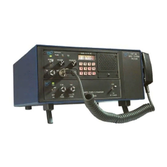
SECTION 1 GENERAL DESCRIPTION INTRODUCTION The VHF/AM Portable Transceiver System P/N 910600-1, manufactured by Technisonic Industries Limited, is a portable, microprocessor controlled, simplex transceiver complete with battery, antenna and microphone operating over the frequency range of 117.975 MHz to 138.000 MHz. The Portable base station system is intended for temporary or backup base station operation in an airport environment. - Page 6 Figure 1-1 TPS-250 Portable Transceiver - General View (Closed & Open View)
-
Page 7: Transceiver Front Cover Assembly
Figure 1-2 Transceiver Front Cover Assembly... -
Page 8: Microphone P/N 861902-1
1.2.2 Transceiver Model TiL-91-DE P/N 901006-2 (continued) To improve the rejection of interfering signals, dual conversion receiver technology has been incorporated on the Transmitter/Receiver (Module A1) board used in Model 91-DE Transceiver. The second IF is 455kHz using a ceramic filter, which is immune to high energy ringing. The dual conversion module also has a second local oscillator, second mixer and ceramic filter. -
Page 9: Scan, Search, And Toggle Modes
Transmission will occur on the channel frequency displayed on the Liquid Crystal Display (LCD). Frequency is determined by keypad entry of the operating frequency or by recalling a stored channel. RECEIVE MODE - When the PTT switch on the microphone is released, the transceiver operates in the receive mode. -
Page 10: Ac/Dc And Battery Operation
RECORD OPERATION - An independent 600 ohm audio output provides combined transmit and receive audio signals for recording of communication. An Internal jumper can be set to provide a floating output or ground referenced output. 1.3.4 AC/DC and Battery Operation The unit can be operated by external 120 VAC, external 28 VDC, or internal battery power. -
Page 11: Portable System Leading Particulars
TABLE 1-1 PORTABLE SYSTEM LEADING PARTICULARS GENERAL: Power Requirements: AC Input Voltage/Current ..... . . 100 to 132 VAC @ 1.5 Amp DC Input Voltage/Current . -
Page 12: Battery Operation
TABLE 1-1 PORTABLE SYSTEM LEADING PARTICULARS (Continued) RECEIVER (Continued): Unwanted Radiation ......Less than 80 µvolts into 50 S Hum &... -
Page 13: Preparation For Use And Storage
SECTION 2 PREPARATION FOR USE AND STORAGE INTRODUCTION This section provides the information required for custom configuration of the system, removal and replacement of batteries, and storage. Custom system configuration includes customizing channel frequencies and remote control set up. Channels 0 to 9 can be configured for fixed frequency operation including transmit inhibit on preselected channels. - Page 14 Figure 2-1 Battery Installation and Removal...
-
Page 15: Battery Installation & Removal
BATTERY INSTALLATION & REMOVAL 2.2.1 Battery Removal Remove Cover Assembly as described in paragraph 2.1.1. Refer to Figure 2-2 for location of items indicated below. Disconnect (+) and (-) Terminal lugs (12) on Battery (13). Disconnect 3 Ribbon Cable Connectors (9) on Control Board (8). Disconnect External DC cable connection (10) on Control Board. - Page 16 Loop RF Cable (item 19) between Linear Amplifier (21) and Control Board Bracket. Reconnect to Transceiver. Secure D-type Connector (15) to rear of chassis with 2 screws, 2 lock washers, and 2 nuts (13). NOTE Screws are difficult to position in unit. Tilt entire unit and hold screws in position with tweezers or small needle nose pliers.
-
Page 17: Fixed Channel Frequency Set Up
FIXED CHANNEL FREQUENCY SET UP The following procedure fixes preselected channel frequencies and inhibits transmit on receive only channels. After completion of this procedure the operator will be able select stored channels only for receive or transmit. Keypad entry of frequencies is disabled. 2.3.1 System Configuration Configure channel frequencies as desired (Refer to Section 3.4.5). -
Page 18: Fixed Channel Jumper Locations
Figure 2-2 Fixed Channel Jumper Locations... -
Page 19: Transceiver Replacement
Position Transceiver Cover (3) on Chassis (4). Ensure that cover holes are aligned with threaded inserts. Position 12 flathead screws (1) and 3 Panhead screws (2) through cover (3) holes into chassis (4) threaded inserts. Tighten screws with fingers. Tighten screws securing Transceiver Cover (3) to Chassis (4). 2.3.4 Transceiver Replacement Position Transceiver (20) in Case Assembly. -
Page 20: Remote Operation - Jumper Locations
Figure 2-3 Remote Operation - Jumper Locations... -
Page 21: Remote Operation Set Up
REMOTE OPERATION SET UP The Procedures listed below enable the user to custom configure the unit for external remote control hardware. Refer to Table 2-1 for connector pin details on Remote Control D Connector located at rear of Case Assembly and Table 2-2 for Jumper Functions. The Record audio output and Remote audio line level is factory set for -8 dBm. -
Page 22: Loudspeaker, Headphone Installation
TABLE 2-1 REMOTE CONTROL CONNECTOR FUNCTIONS PIN NO FUNCTION Remote TX Audio High Remote Recorder Audio High Remote Rx Audio High +24 Vdc Remote Rx Audio Low Remote Tx Audio Low Single Line Keying Remote Recorder Audio Low Ground TABLE 2-2 REMOTE CONTROL JUMPER FUNCTIONS JUMPER LOCATION... -
Page 23: Headset
2.5.2 Headset Headset impedance should be 150 to 600 ohms. The headset cable must terminate in a 1/4 in. 3-pole telephone plug (male), to mate with the SPEAKER/PHONE jack located on the front panel of the transceiver. The internal loudspeaker is automatically disconnected. Connect the headset as indicated below for receiver audio with or without transmit audio. -
Page 24: Operating Instructions
SECTION 3 OPERATING INSTRUCTIONS INTRODUCTION This section includes a functional description of each switch, control, indicator and connector located on the front and rear panels of the portable transceiver, including the PRESS-TO-TALK switch located on the microphone. Operating instructions for transmit/receive and the special functions are also included. - Page 25 Figure 3-2 Transceiver Front and Rear Panel Layout...
- Page 26 TABLE 3-1 OPERATORS SWITCHES, CONTROLS AND INDICATORS SWITCHES CONTROLS & FUNCTIONAL DESCRIPTION INDICATORS POWER A toggle switch applies the 27.5 volts nominal power supply to the ON/OFF transceiver. The transceiver is switched to ON in the toggle UP position SWITCH the transceiver is switched OFF in the toggle DOWN position.
- Page 27 TABLE 3-1 OPERATORS SWITCHES, CONTROLS AND INDICATORS (Continued) SWITCHES CONTROLS & FUNCTIONAL DESCRIPTION INDICATORS LIQUID A 5½ digit Liquid Crystal Display (LCD) displays the FREQUENCY/ CRYSTAL CHANNEL that the transceiver is currently operating on. IN SCAN mode DISPLAY it displays the current frequency scanned if RF signal is present. LOUDSPEAKER An 8-ohm internal speaker reproduces the receiver audio output.
- Page 28 TABLE 3-1 OPERATORS SWITCHES, CONTROLS AND INDICATORS (Continued) SWITCHES CONTROLS & FUNCTIONAL DESCRIPTION INDICATORS BAT TEST Single pole pushbutton switch provides for manual battery charge level test. Results are indicated by the Batt Low LED indicator or BATT charged LED indicator. BAT LOW LED A RED LED Indicates that battery charge is less than 21.6 Vdc and that INDICATOR...
-
Page 29: General Operating Instructions
GENERAL OPERATING INSTRUCTIONS 3.3.1 Preparation for Use To prepare the transceiver for use (Refer to Figures 1-2, 3-1 and Table 3-1). Location for Transmit/Receive Operation. The VHF frequency band is essentially line of site communication. When selecting a location there should be no obstacles between the communicating radio sites. Objects greater than two metres will reflect The RF signal and foliage greatly attenuates signal strength. -
Page 30: Transmitter Operation
Select AC Power, External DC Power, or Battery Operation. Refer to Paragraphs 3.5 to 3.7). Remove the microphone from front access panel, and ensure that the microphone connector is connected to the MIC/PTT connector of the transceiver. Set the SQUELCH control in the fully counter-clockwise (CCW) position. Set the VOLUME control in the 12 o'clock centre position. -
Page 31: Receiver Operation
Hold the microphone in one hand, with the upper edge of the microphone as close as Possible to the upper lip. NOTE This technique activates the noise cancelling feature of the microphone. The microphone is most effective when sound is ½ inch (12.7 mm) or more away from the microphone. -
Page 32: Switching Off
Recommended procedure: The squelch taper on a dual conversion receiver looks as follows: Squelch knob position Squelch setting 12 o’clock 0.5uV 3 o’clock 1.2uV 3:30 position 2.5uV 4 o’clock Fully clockwise It is recommended that the squelch be set to at least 2.5uV (3:30 knob position) at busy airport locations. -
Page 33: Front Panel Keypad Operation
FRONT PANEL KEYPAD OPERATION All frequencies within the range of 117.975 MHz to 138.000 MHz can be stored on channels 0 to 9 in 25 KHz steps. Channels and feature settings are stored in non-volatile memory. Removal of external power source or batteries will not erase stored channels, key "Beep" set up, Keypad and LCD display lighting set up, 90 second Tx time-out set up or Tx Inhibit selections. -
Page 34: Keypad "Beeps
3.4.1 Keypad "Beeps" Audible "Beeps" are generated when a key is pressed (default condition). Tones can be enabled/disabled by toggling the "E","8" keys. +), +), Press to disable Key "Beeps". .)- .)- +), +), Press to enable Key "Beeps". .)- .)- 3.4.2 Keypad and LCD Display Lighting Three Display and keypad lighting modes are available to the operator. -
Page 35: Storing A Frequency To A Channel
NOTE Entry of 117 MHz fills 975 in remaining digits. Entry of 138 Mhz fills 000 in remaining digits. 4th Digit - Can be any digit. 5th + 6th Digits are paired. Entry of 5th digit 0 results in 00 displayed. Entry of 2 results in 25. -
Page 36: Recalling A Stored Channel
+), +), +), +), +), +), +), Press .)- .)- .)- .)- .)- .)- .)- Frequency 119.750 MHz is stored as channel 1. +), +), +), +), +), Press .)- .)- .)- .)- .)- 138.000 MHz as channel 2. 3.4.6 Recalling a Stored Channel To recall the permanently stored emergency channel 121.500 MHz press "E","0". -
Page 37: Toggling Between Two Channels
3.4.8 Toggling Between Two Channels +), +), Press to recall previous channel. .)- .)- Example: Recall Channel 0 as described in para 3.4.3 117.975 will be displayed. Recall Channel 2 138.000 will be displayed. +), +), Press .)- .)- 117.975 will be displayed. +), +), Press .)- .)-... -
Page 38: Ac Operation
NOTE PTT is inhibited during SCAN mode. Pressing PTT once exits SCAN mode. Pressing PTT twice is required to Key the Transmitter. +), +), Press to enter SCAN mode. .)- .)- Press PTT to Lock on SCANned Frequency or Press to exit SCAN. - Page 39 BATTERY OPERATION Set Ext DC/INT AC/DC switch to INT AC/DC. Set BATTERY switch to ON. Press BAT TEST switch. Battery CHG'D indicator shall light. If BAT LOW indicator lights, charge unit before using in Battery Mode. 3.7.1 Battery Charging Completely discharged batteries will require 6 Hrs to charge to 95% capacity or 8 Hrs to charge to 100% capacity.
Need help?
Do you have a question about the TiL-91-DE/S and is the answer not in the manual?
Questions and answers