Camus Hydronics DynaMax DMH081 Installation, Operation And Service Manual
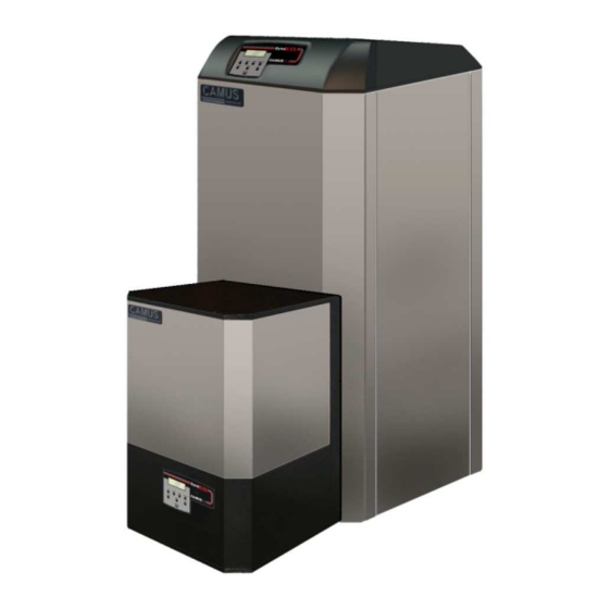
Dynamax series gas fired wall hung & floor mount residential commercial stainless steel boilers
Hide thumbs
Also See for DynaMax DMH081:
- Installation, operation and service manual (82 pages) ,
- Installation, operation and service manual (76 pages)
Table of Contents
Advertisement
INSTALLATION OPERATION
AND SERVICE MANUAL
GAS FIRED WALL HUNG & FLOOR MOUNT RESIDENTIAL
COMBINATION HEATING/HOT WATER SUPPLY
WARNING:
If the information in these instructions is not followed
exactly, a fire or explosion may result causing property
damage, personal injury or death
Do not store or use gasoline or other flammable
vapours and liquids in the vicinity of this or any
other appliance.
WHAT TO DO IF YOU SMELL GAS
Do not try to light any appliance,
o
Do not touch any electrical switch; do not
o
use any phone in your building,
Immediately call your gas supplier from a
o
neighbour's phone. Follow the gas
supplier's instructions,
If you cannot reach your gas supplier, call
o
the fire department.
Qualified installer, service agency or the
gas supplier must perform installation and
service.
To the Installer: After installation, these instructions
must be given to the end user or left on or near the
appliance.
To the End User: This booklet contains important
information about this appliance. Retain for future
reference.
CAMUS
6226 Netherhart Road, Mississauga, Ontario, L5T 1B7
COMMERCIAL STAINLESS STEEL BOILERS
DynaMax SERIES
HYDRONIC HEATING
Models; DMH081, 101, 151, 201, 251,
211, 261, 291, 391, 501, 601, 701, 801
HOT WATER SUPPLY
Models; DMW082 ,102, 152, 202, 252,
212, 262, 292, 392, 502, 602, 702, 802
Models; DMC083, 103, 153, 203, 253,
213, 263, 293, 393, 503, 603, 703, 803
HYDRONICS
LTD.
99-0056
Rev. 3.2
Advertisement
Table of Contents

Related Manuals for Camus Hydronics DynaMax DMH081


Summary of Contents for Camus Hydronics DynaMax DMH081
- Page 1 GAS FIRED WALL HUNG & FLOOR MOUNT RESIDENTIAL COMMERCIAL STAINLESS STEEL BOILERS DynaMax SERIES HYDRONIC HEATING Models; DMH081, 101, 151, 201, 251, 211, 261, 291, 391, 501, 601, 701, 801 HOT WATER SUPPLY Models; DMW082 ,102, 152, 202, 252, 212, 262, 292, 392, 502, 602, 702, 802 COMBINATION HEATING/HOT WATER SUPPLY Models;...
-
Page 3: Table Of Contents
Contents PART 1 GENERAL INFORMATION ............................1 INTRODUCTION................................1 SPECIAL INSTRUCTIONS TO OWNER ..........................1 CHECKING EQUIPMENT ............................... 1 DISPLAY UNIT ................................1 SEQUENCE OF OPERATION ............................1 1.5.1 Heat Transfer Process ..............................1 1.5.2 End of Sequence................................2 INSTALLATION CODES ..............................2 WARRANTY .................................. - Page 4 5.4.1 Manual Reset Codes ..............................20 5.4.2 Automatic Reset Codes ............................. 20 PART 6 CONTROL PANEL ............................... 21 DYNAMAX CONTROLLER ............................21 SETTING THE DYNAMAX CONTROLLER ........................21 CENTRAL HEATING MODES ............................21 DOMESTIC HOT WATER MODES ..........................22 PART 7 COMPONENTS ................................
- Page 5 11.12 FREEZE PROTECTION FOR INDOOR & OUTDOOR INSTALLATIONS ................57 11.13 FREEZE PROTECTION FOR A HEATING BOILER SYSTEM (Optional) ................58 PART 12 INSTALLATIONS ................................. 58 12.1 CHECKING THE INSTALLATION ........................... 58 12.2 CHECKING THE CONSTRUCTION ..........................58 12.3 HEATING BOILER INSTALLATIONS ..........................58 12.4 INSPECT &...
-
Page 6: Part 1 General Information
DynaMax Controller will allow the performed only by a qualified installer/technician that is gas valve to remain open. The burner is now firing at trained by Camus Hydronics. The serviceman must utilize a starting input rate. combustion analyzer with CO... -
Page 7: End Of Sequence
1.5.2 End of Sequence carefully followed in all cases. Authorities having jurisdiction shall be consulted before installations are made. In the Setpoint temperature is satisfied. absence of such requirements, the installation shall Power to the gas valve is turned off. conform to the latest edition or current as amended of the Combustion Air Fan ramps to a stop over the factory National Fuel Gas Code, ANSI Z223.1 and/or CAN/CGA-... -
Page 8: Boiler/Furnace Room Operating Condition
deficiency, which could cause an unsafe condition. Confirm proper operation of all safety devices • Check for gas leaks and proper vent operation. Insofar as is practical, close all building doors and windows and all doors between the spaces in which the appliances remaining connected to the common venting system are located and other NOTE... -
Page 9: Clearance From Combustible Material
• Figure 2: Floor Mount Clearance from Combustibles The appliance designed for indoor installation (Indoor Models) must be installed indoors where it is protected from exposure to wind, rain and weather. • The appliance designed for outdoor installation (Outdoor Models) must be installed outdoors. Always consider the use of a shelter such as a garden shed in lieu of direct exposure of the appliance to the elements. - Page 10 Table 2: DynaMax Wall Hung Service Clearances Service Clearance, Inches (cm) Model Front Right Side Left Side Rear 24” (61cm) 3” (8 cm) 4” (10 cm) 4” (10 cm) 0” (0 cm) 24” (61cm) 3” (8 cm) 4” (10 cm) 4”...
- Page 11 Table 4: DynaMax Floor Mount Service Clearances Service Clearance, Inches (cm) Model Front Right Side Left Side Rear 12” (31cm) 24” (61cm) 0” (0cm) 12” (31cm) 14” (36 cm) 12” (31cm) 24” (61cm) 0” (0cm) 12” (31cm) 14” (36 cm) 12”...
- Page 12 Figure 5: DynaMax Wall Hung Service Clearances Figure 6: DynaMax Floor Mount Service Clearances...
-
Page 13: Part 2 Air Inlet And Venting
are in compliance with the instructions provided and PART 2 AIR INLET AND VENTING satisfy requirements of all applicable codes. NOTE It is extremely important to follow these venting All vent pipes must be properly assembled and supported, instructions carefully. Failure to do so can cause severe and the exhaust must be pitched a minimum of 1/4 inch per personal injury, death or substantial property damage. -
Page 14: Category Ii Venting
Table 6: Maximum Flue Temperature for Various Vent Materials * Consult factory for recommendations applicable to venting combinations not shown above. Vent Material Maximum Flue Temperature [ CATEGORY II VENTING A category II appliance may be combined into a common negative pressure venting system designed to ASHRAE CPVC requirements using a proven vent sizing program. -
Page 15: Vent Termination And Air Inlet Clearances
Vent outlet MUST NOT terminate below a forced air Air inlet point for multiple boiler air inlets must be provided with an exterior opening which has a free area equal to or inlet at any distance. greater than the total area of all air inlet pipes connected to Vent cannot terminate below grade. -
Page 16: Sidewall Concentric Vent/Air
Location of a Sidewall Air Inlet Cap CAUTION Total length of piping for air inlet must not exceed Do not operate appliance with the rain cap removed as this the limits stated in Table 7. may result in the recirculation of flue products. Water may Point of termination for the sidewall air inlet cap also flow into the combustion air pipe and into the burner must be located a minimum of 12 inches (0.30m) - Page 17 Location of a Vertical Air Inlet Opening be expected. Adjacent brick or masonry surfaces The total length of piping for inlet air must not should be protected with a rust resistant sheet metal exceed the limits given in Table 8. plate.
-
Page 18: Part 3 Gas Connection
The appliance and its individual gas shut-off valve must be PART 3 GAS CONNECTION disconnected from the supply piping when pressure testing the gas supply piping at pressures above ½ PSI Verify that the appliance is supplied with the type of gas specified on the rating plate. -
Page 19: High And Low Gas Pressure Switches (Optional)
Figure 16: DynaMax 500 – 800 1:1 Air/Gas Ratio Control IMPORTANT Valve Upon completion of initial installation or following any repair work on the gas system, leak test all gas connections with a soap solution while the main burner is firing. Immediately Lift top cover to access high fire repair any leak found in the gas train or related components. -
Page 20: Part 4 Water Connection
Regulated Gas Supply Pressures for DynaMax Boilers & PART 4 WATER CONNECTION Water Heaters • Check all applicable local heating, plumbing and A stable gas supply pressure is important to avoid rough building safety codes before proceeding. starts with machines like the DynaMax which use a 1 to 1 •... -
Page 21: Warning Regarding Chilled Water Systems
WARNING REGARDING CHILLED WATER HEAT EXCHANGER SYSTEMS This appliance uses precision formed stainless steel tubing to maximize the heat transfer process and achieve 97% When an appliance is connected to an air conditioning steady-state efficiency. This heat exchanger is designed to system where the same water is used for heating and withstand 160 PSIG working pressure. - Page 22 Table 11: Flow and Pressure Drop at a Given Table 12: Flow and Pressure Drop at a Given Temperature Rise (Hydronic Heating) Temperature Rise (DHW) 30 ° F (16.7 °C) 35 ° F (19.4 ° C) 20 °F (11.1 ° C) Input, Temp Rise Temp Rise...
-
Page 23: Flow Proving Device (Wall Mount Models And Combination Models Only)
CAUTION FLOW PROVING DEVICE (wall mount Remove jumper when connecting to 24 VAC circuit. models and combination models only) Figure 20: Low Water Cut Off Electrical Figure 19: Flow Proving Device Connections (Watts) WARNING: Be sure to remove the jumper between H and P1 From Flow Switch... -
Page 24: Part 5 Electrical & Controls
HIGH LIMIT PART 5 ELECTRICAL & CONTROLS A manual reset fail-safe high limit aqua-stat control is inside the appliance and the control bulb is installed in a dry well in the heat exchanger outlet. The setting of this control limits maximum discharge water temperature to 210 F (CPVC, IT IS EXTREMELY IMPORTANT THAT THIS UNIT BE... -
Page 25: Error Table
and then “ON” or cycling the thermostat will not reset a hard To eliminate the hard lockout error, lockout condition. Wait five seconds after turning on the main Wait until the boiler has completed its post-purge power before pushing the RESET button when the DynaMax cycle, if applicable Controller is in a manual reset condition. -
Page 26: Part 6 Control Panel
Mode 1: Central Heating with Outdoor Reset and Thermostat PART 6 CONTROL PANEL Control DYNAMAX CONTROLLER This mode will only function when an outdoor sensor is connected. The set point is calculated depending on the The appliance is provided with an operator interface panel at outdoor temperature and the burner will react on the room the front. -
Page 27: Domestic Hot Water Modes
Burner Stop: Mode 2: Central Heating with Outdoor Reset DHW Temp > DHW Setpoint + DHW store supply extra + This mode will only function when an outdoor sensor is DHW supp hyst up connected. The set point is calculated depending on the outdoor temperature. -
Page 28: Part 7 Components
7.3 COMBUSTION AIR FAN PART 7 COMPONENTS DynaMax uses a modulating air fan to provide combustible 7.1 DIRECT SPARK IGNITER air/gas mix to the burner and push the products of combustion through the heat exchanger and venting system. The direct spark igniter is inserted directly through the The fan assembly consists of a sealed housing and fan combustion chamber front door and held in place by two wheel constructed from spark resistant cast aluminum. -
Page 29: Part 8 Labvision Software
PART 8 LABVISION SOFTWARE Press [Browse] and locate the D2XX file on your computer and press [Next>] NOTE LabVision software is available on request from the factory and is not shipped with the boiler/ water heater. LabVision is compatible with Windows XP (32-bit, 64-bit) / Windows 7 (32-bit, 64-bit) operating systems. -
Page 30: Adjusting Fan Speeds
• Go to Options > Communication > Preferences NOTE • Do not make any other parameter or setting changes other A Preferences screen will pop up • than those stated in the manual as they will have a Under the Project Tab in the Protocol box select the detrimental effect to the DynaMax. -
Page 31: Labvision Central Heating
Table 18: Appliance Type Designations The CH demand switches between on/off depending on whether or not there is a demand for central heating. The other parameters are designed for internal control purposes. Appliance DynaMax Appliance Figure 35: Central Heating Input Screen Type Model Type... -
Page 32: Central Heating Mode = 1, 2, 3 Installer Level
The Anti_Cycle_Period is designed to prevent the boiler from LABVISION DOMESTIC HOT WATER short-cycling. The preset time must be satisfied before the Use the pull down menu and select DHW Mode 4 to adjust boiler will start up. parameters. Before the parameters can be adjusted the blue 8.5.2 Central Heating Mode = 1, 2, 3 Installer Level status bar must track left-to-right and back again. -
Page 33: Dhw Mode 4, Installer Level
The following parameters can be adjusted: Figure 41: DHW Mode 4 Screen Table 22: DHW Mode 1, 2 Parameters Parameter Parameter Description To provide a target set point for the DHW_Setpoint storage tank. (Default: 120 To detect the start of a storage DHW store hyst up tank demand. -
Page 34: Labvision Cascade
DHW Priority LABVISION CASCADE When both a CH demand and DHW demand exist When connected in a cascade setup the Master boiler can simultaneously, DHW will always have priority. When DHW control up to 7 slave boilers (ie. a total of 8 boilers) from the demand ends the boiler will check the Outlet Temperature control panel of the Master Boiler. -
Page 35: Data Logging
Staging Operation DATA LOGGING The control supports a function to rotate the boilers on a LabVision software also comes equipped with data logging timely basis. With parameter CC_STAGE_TIME the time can capability which has the ability to track return/supply, DHW be set after which the start and stop sequence of the temperatures, actual and target fan speed, state and status cascade boilers changes. -
Page 36: Procedure For Viewing Log Files In Microsoft® Excel
feature disabled the log file will be dependent on time as 8.8.2 Analysis of Microsoft® Excel Log File opposed to memory size. The log file parameters are divided into columns with a Figure 49: Unlimited Log File Size reference to the time of data collection on each row. The Status and State parameters are identified by numbers and these can be translated into a description, listed below. -
Page 37: Error History
Error History Table 28: Temperature Conversion LabVision has the ability to record past blocking (E) and lockout (A) errors. To access this feature use the pull down Temperature Quick Reference menu and select History. Figure 50: Error History The blocking and lockout errors are separated into their own respective rows and are identified by their respective error codes. -
Page 38: Dynamax Control Panel
PART 9 DYNAMAX CONTROL PANEL ENTER • • Press to ENTER to Press to enter Main MENU confirm selection or Menu. This provides to confirm a access to System parameter change Monitor, Settings, Programs and Errors RESET NEXT DOWN • Press to change boiler parameter •... -
Page 39: Introduction To The Dynamax Control Panel
Figure 54: DynaMax Home Screen INTRODUCTION TO THE DYNAMAX CONTROL PANEL For times when a notebook computer is not available, a service technician will still be able to perform all the functions described in LabVision, except for the logging aspect. The menu structure for the DynaMax Control Panel was The display panel then defaults to the next screen which designed to be intuitive and easy to use for a first time user. -
Page 40: Menu Screen
MENU SCREEN From TEMPERATURE AND STATUS display; Press [MENU] button. Display Display Description Readout Monitor Central Heating and DHW System settings, if equipped. System Monitor will be open to all levels of access. Monitor Changes to Languages, Date and Time, and Units of measurement. The Display default setting is English, Fahrenheit Options... -
Page 41: System Monitor Display
SYSTEM MONITOR DISPLAY From MENU display; 1) Use [NEXT] to select ‘System Monitor’ 2) Press [ENTER] Display Display Readout Description Boiler is designated as a Master MASTER Active boiler in the cascade setup Program Boiler is designated as a Slave boiler SLAVE in the cascade setup Pump is active... -
Page 42: Display Options Display
DISPLAY OPTIONS DISPLAY From MENU display; Use [PREVIOUS]/[NEXT] button to select ‘Display Options’. Press ENTER Display Display Readout Description Allows the control to be set to Language English (default), French or Spanish Allows the Date and Time to be Date and Time changed Allows the control to be set to Units... -
Page 43: Central Heating Display
CENTRAL HEATING DISPLAY Use [PREVIOUS]/[NEXT] button to select ‘Appliance Settings’. Press ENTER Display Display Readout Description Enters Central Heating branch of Central Heating display Allows adjustment of Setpoint. The Setpoint Setpoint is controlled to the boiler outlet sensor. (Default: 160 Use [NEXT] to enter INSTALLER ACCESS display Use [UP/DOWN] to enter... -
Page 44: 9.6 Domestic Hot Water Display
Display Display Readout Description Temperature for night time usage T_night_reduction This parameter is only engaged (Mode 2,3) when the external clock is satisfied. (Default: 18 When the outdoor temperature is below the preset Weather_setpoint a CH demand is created. Therefore, Weather_setpoint the CH demand is not dependent on (Mode 2) - Page 45 Display Display Readout Description DHW_Store_Hyst_Up Used to end a call for heat (Mode 1) (Default: 9 DHW_Store_Hyst_Down Used to start a call for heat (Mode 1) (Default: 4 Increases the target outlet DHW_Store_Supply_Extra temperature (Mode 1) (Default: 20 Temperature above set point to stop DHW_Supp_Hyst_Up burner for DHW.
-
Page 46: Cascade Control
9.7 CASCADE CONTROL Use [PREVIOUS]/[NEXT] button to select ‘Appliance Settings’. Press ENTER Display Display Readout Description Cascade Control Enters Cascade branch of display Use [UP]/[DOWN] to select the option of a ‘MASTER Boiler’ or ‘SLAVE Boiler’. Press [ENTER] to confirm. If ‘SLAVE Boiler’... -
Page 47: Boiler Control
BOILER CONTROL Use [PREVIOUS]/[NEXT] button to select ‘Boiler Control’. Press ENTER Display Display Readout Description Enters Boiler Control branch of Boiler Control display Select the appliance model Appliance Type Selection parameters associated with each model Adjust the ignition fan speed. Ignition Fan Speed (Default: 3000 RPM) Select the vent material which is... -
Page 48: Part 10 Troubleshooting
PART 10 TROUBLESHOOTING Table 29: Troubleshooting Table COMPONENT FAILURE MODE ANALYSIS • Two wires interchanged • No effect on safety Incoming Power • Live and Neutral wires are interchanged. • The 24Volts and 120 Volts • Transformer immediately burns out, replace Transformer wired are interchanged transformer... - Page 49 SYMPTOM FAILURE MODE ANALYSIS • The boiler has failed to ignite • Verify that all air has been purged from gas line the burner after 3 unsuccessful • Inspect spark electrode and related wiring for attempts damage and connection errors •...
- Page 50 SYMPTOM FAILURE MODE ANALYSIS • Supply Gas Issue • Refer to Part 3 Gas Connection in this manual. • Natural Gas Pressure should read between 3” w.c. and 14” w.c. • L.P. Gas Pressure should be at 11” w.c. • Air/Gas Mixture Issue •...
- Page 51 SYMPTOM FAILURE MODE ANALYSIS • Stack temperature has • Measure the resistance of the flue sensor at room exceeded the limit set on the temperature, it should be approximately 10kΩ. Flue Gas Error boiler. • PVC: 149 • CPVC: 194 •...
- Page 52 Ignition Error displayed on screen An ignition error occurs when 3 consecutive attempts at lighting the burner have failed. This is a manual reset error where the technician must press RESET to clear the error. Check ignition speed is between Adjust ignition speed 2500 to 3000 RPM using to 3000 RPM...
- Page 53 Fan Error displayed on screen A fan error is displayed when the difference between the target and actual fan speed is greater than 300 RPM apart for over a minute. This is a manual reset error where the technician must press RESET to clear the error. Replace ignition Check software version on module (848-MN) and...
- Page 54 Blocked Flue Error displayed on screen This error can indicate a blocked flue or blocked intake condition, low gas pressure switch tripped (optional) or high gas pressure switch tripped (optional). To identify the safety that is open use the continuity setting on your multimeter and go across the contacts of the switches.
- Page 55 Flow Switch not closed displayed on screen The flow switch is not closed or the low water cutoff (LWCO, optional) was tripped. This is an automatic reset error and as soon as flow is proven this error resolves itself. To identify the safety that is open use the continuity setting on your multimeter and go across the contacts of the switches.
- Page 56 Flue Gas Error displayed on screen A flue gas error occurs when the stack temperature has exceeded the maximum limit allowed by the vent material. This is an automatic reset error, when the stack temperature drops 20 F below the limit allowed the boiler is allowed to restart and an ignition attempt is made if the call for heat is not yet satisfied.
- Page 57 Flame appears and disappears within 4 seconds of ignition This type of failure indicates a flame rectification signal issue through the flame rod. Fasten flame sensor plug securely to Is Flame sensor plug secure? flame sensor wire and check for corrosion deposits at wire terminals Replace sensor wire since corrosion Check continuity of flame...
-
Page 58: Setting The Correct Combustion
10.1 SETTING THE CORRECT COMBUSTION To adjust the high-fire setting Use the DynaMax Control Panel Switch the main power off to the boiler by placing the toggle switch in the ‘OFF’ position Press the [MENU] button > select Appliance Settings and press [ENTER] >... - Page 59 DM 299 – 399 DM 500 – 800 Figure 57: DM 299 – 399 Gas Valve Figure 58: DM 500 - 800 Gas Valve Low-fire air gas ratio adjustment Lift top cover to access high fire (use Torx 40 for adjustment, air/gas ratio adjustment (use 3mm clockwise increases CO allen key for adjustment, counter-...
-
Page 60: Part 11 Maintenance
CAUTION It is important that all gas appliances be serviced by a qualified technician trained by Camus Hydronics. It is in your own interest and that of safety to ensure that all local codes, and all the “NOTES” and “WARNINGS” in this manual are complied with. -
Page 61: Condensate Treatment
NOTE 11.5 IGNITER AND FLAME SENSOR ELECTRODES All gaskets on disassembled components must be replaced The direct spark igniter is to be checked at every service with new gaskets/sealant on re-assembly, if required. Gasket interval. Clean the direct spark igniter as required to maintain kits are available from the factory peak ignition efficiency. -
Page 62: Removal Of Combustion Chamber Lining
• NIOSH approved respirators, Remove the direct spark igniter and the flame manufacturers, and phone numbers are sensor. • also listed on this website. Remove the T-25 screws holding the front burner Wear long-sleeved, loose fitting clothing, flange in place to gain access to the burner. •... -
Page 63: Freeze Protection For A Heating Boiler System (Optional)
provide adequate freeze protection. PART 12 INSTALLATIONS • Freeze protection for the appliance using an indirect coil can be provided by using hydronic system antifreeze. WARNING Follow the manufacturer’s instructions. DO NOT use Before starting the boiler, smell near the floor and around the undiluted or automotive type antifreeze. -
Page 64: Inspect & Recharge Condensate Collection/Neutralizing Reservoir
Placing the Boiler in Operation Pipe supports could allow the pipe to slide resulting in noise transmitted into the system. Padding is recommended. The Pre-Start Check List boiler pressure relief valve must be piped to a suitable floor Review the location of the boiler, clearances drain. -
Page 65: Domestic Hot Water With Storage Tank
Boiler Operation 12.10 TEMPERATURE RISE AT FULL FIRING RATE Appliance should begin the start-up process for the sequence of operation. The pump must run continuously when the burner is The boiler will fire at approximately 50% of firing. rated input on initial start-up and adjust input With the pump running and the burner in the off cycle, as required to meet system demand. -
Page 66: Setting The Correct Combustion
Table 32: Temperature Rise across Heat Exchanger 12.11 SETTING THE CORRECT COMBUSTION (Hydronic Heating) Refer to Section 10.1 Setting the Correct Combustion. TEMPERATURE RISE ACROSS HEAT EXCHANGER 12.12 CASCADE SETUP F (19.4 MODEL F (16.7 The following components are needed for a Cascade setup [BTU/hr] DynaMax Ignition Control Board (848-MN) USGPM... - Page 67 Figure 62: Text Display Switch Setup Figure 63: Text Display Detail Wiring Setup Refer to Figure 63 for a pictorial description of how to connect the Cascade system together. Master Boiler The following needs to be done to the Master Text Display: Connect the “To 848MN control”...
-
Page 68: Interface Module (If Equipped)
Slave Boiler Figure 65: Text Display Switch Setup Turn on the DynaMax Slave Boiler and wait until the Date and Time to appear. 11) Press [MENU] 12) Select “Appliance Settings” using the [NEXT] button and press [ENTER]. 13) Select “Cascade Control” using the [NEXT] button and press [ENTER]. - Page 69 Table 34: Modbus Configuration Table 36: Ignition Module Status Modbus Configuration MN STATUS Modbus RTU Protocol STATUS State Name Description 0x01 (settable with LabVision) Default slave address Dec. Standby (Waiting for Supported Modbus Read holding registers (0x03) 0x00 STANDBY demand) commands Write single holding register 0x0E...
- Page 70 Table 38: Manual Reset Error Table 39: Automatic Reset Errors Automatic Reset Manual Reset Errors Decimal Description Decimal Description Errors E2PROM_READ_ERROR No communication with E2Prom REFHI_TOO_LO_ERR Three unsuccessful ignition attempts in Internal hardware error IGNIT_ERROR a row Problems with Gas Valve Relay = REFHI_TOO_HI_ERRO GV_RELAY_ERROR Internal Hardware Error...
-
Page 71: Write Functionality
12.14 Write Functionality 12.14.2 Write DHW Setpoint The DynaMax Ignition module may be only reset when it is in Issue a Modbus write single holding register error. Only manual reset errors can be reset by writing command writing 0x001 to the Reset & R/W Control 0x4000 to the Reset &... -
Page 72: Alarm Output (If Equipped)
12.15 Alarm Output (if equipped) Table 42: Analog Input Selection This is a feature that is offered on the 848IF. An alarm output ANLG_IN_MODE Configuration is available to signal was sensed in the connected heating Mode Name Description system. Once an alarm is signalled by the alarm output it Analog Input not Enabled can be reset by means of the External Reset Input. -
Page 73: Ignition Cycle
12.19 IGNITION CYCLE The ignition cycle is shown in the table below. The values are the default factory settings. Table 44: DynaMax Ignition Cycle Post State Standby Pre Purge Safety ON Safety OFF Ignit_0 Ignit_1 Burn Purge_0 5s after fan Limited to 24 speed is Min. -
Page 74: Part 13 Piping Diagrams
PART 13 PIPING DIAGRAMS Figure 69: Single Boiler Hydronic Heating Zoned Piping Arrangement This piping arrangement is designed for: Central Heating Mode: 0, 1, 2, or 3 DHW Mode: 0 Boiler Address: 100 Pressure Reducing Valve Pressure Gauge Expansion Tank Zone Circulator Ball Valve... - Page 75 Figure 70: Single Combination Boiler Zoned Piping Arrangement Central Heating Mode: 0, 1, 2, or 3 DHW Mode: 4 Boiler Address: Boiler Address = 100 Pressure Reducing Valve Pressure Gauge Expansion Tank Zone Circulator Ball Valve Flow Check Separator Valve DynaMax Boiler Temperature / Pressure...
- Page 76 Figure 71: Single Boiler Hydronic Heating & Indirect Storage Tank Zoned Piping Arrangement Central Heating Mode: 0, 1, 2, or 3 DHW Mode: 1, or 2 Boiler Address: Boiler Address = 100 Pressure Reducing Valve Pressure Gauge Expansion Tank Zone Circulator Flow Check Separator...
- Page 77 Figure 73: Single Boiler Hydronic Heating & Direct Storage Tank Zoned Piping Arrangement Central Heating Mode: 0 DHW Mode: 1 or 2 Boiler Address: Boiler Address = 100 Cold Water In Water Out Anti-Scald Mixing Valve Cold Water In Sensor Union Direct DHW Tank...
- Page 78 Figure 74: Multiple Boiler Hydronic Heating Zoned Piping Arrangement Central Heating Mode: 0, 1, 2, 3 DHW Mode: 0 Boiler Address: Master Boiler Address = Master Boiler 1 (M1) Slave Boiler Address = Slave Boiler 2 (S2) Pressure Reducing Valve Pressure Gauge Expansion Tank...
-
Page 79: Part 14 Exploded View & Parts List
PART 14 EXPLODED VIEW & PARTS LIST DYNAMAX WALL HUNG... - Page 80 DYNAMAX FLOOR MOUNT...
- Page 81 DynaMax Models Name of Part Part ID 4 + 1 Wall 5 + 2 Wall 8 + 4 Wall 8 + 4 Floor Heat Exchanger 10 + 6 Floor 15 + 8 Floor 18 + 10 Floor 21 +11 Floor 24 + 12 Floor 80,000 BTU 100,000 BTU...
- Page 82 DynaMax Models Name of Part Part ID 110223-305 110223-307 Hydronic PL30 Heating/ Combination PL36 Pump DHW Pump E12B E33B 127091.1.1 GM20-70-011-01 Mixing Chamber GM20-70-020-02 14-5540 Air Pressure 8021205256 Switch VC4011ZZ02/E 3-Way Valve Actuator FSLF24 VCZMR6100/E VCZND6100/U 3-Way Valve Body VBN3EM3POX VBN3FP3POX TCL 110A (CPVC, AL29-...
- Page 83 DynaMax Models Name of Part Part ID 14-5415 Electrical Conduit Plate 14-5415-250 Electrical Strip 14-5416 Plate Plastic Bezel 15-6001-A Bracket for 14-5419 Neutralizer Box Air Inlet/ Vent FSA-HEX03 Adapter Plate Heat LB31-20X Exchanger (Combination LB31-40X Models ONLY) 14-5501-20-25 DynaMax Floor Front Panel 14-5501 14-5502...
- Page 84 DynaMax Models Name of Part Part ID 14-5518-20-25 Floor Bracket Left 14-5518 14-5520-20-25 Floor Rear Bracket 14-5520 Top Cover 14-5521 Assembly DASHBOARD Dashboard Bracket for 14-5525 Neutralizer Box Rubber Bushing 33-0101 Condensate Pan 14-5417 Brace 14-5421 Cover Plate 14-5421-250 Standoff 14-5423 Electrical Strip 14-5420...
- Page 85 DynaMax Models Name of Part Part ID 40VA HCT- Transformer 01E0BB06 Supply/Return NTC- Sensor SENSOR-002 NTC- Flue Sensor SENSOR-003 NTC- Outdoor Sensor SENSOR-004 CABLE Sensor Wire HARNESS NTC- DHW Sensor SENSOR-001 45900400-132/B Gas Valve Elbow 45900400-144/B 45900441-015B Gas Valve Wire Harness 45900429-007B 10-407-05...
- Page 86 DynaMax Models Name of Part Part ID Plastic to 300566 Stainless Steel 300611 Vent Adapter Stainless to FS0604PVCR Plastic Vent 300537 Adapter 1056-22 1056-33 Rubber Air Sleeve 1056-44 1056-55 GM10-25-074-09 Burner Gasket GM10-35-078-03 33-0036 33-0037 Fan Gasket/ Mixing Chamber 33-0038 Gasket 33-0043 33-0057...
-
Page 87: Part 15 Electrical Diagrams
PART 15 ELECTRICAL DIAGRAMS 15.1 DM 80- 250 INTERNAL WIRING DIAGRAM (WALL HUNG MODELS) -
Page 88: Dm 210-299 Internal Wiring Diagram (Floor Mount Models)
15.2 DM 210-299 INTERNAL WIRING DIAGRAM (FLOOR MOUNT MODELS) -
Page 89: 848If Interface Module Wiring Schematic
15.3 848IF Interface Module Wiring Schematic... -
Page 90: Field Wiring
15.4 FIELD WIRING All wires being placed into the terminal block should be horizontal for at least an inch to ensure sufficient electrical conductivity. 15.4.1 System Sensor The temperature of the primary return can be controlled by installing a system sensor. The system sensor must be used in all Cascade modes, and must be enabled through the DynaMax controller or through LabVision. -
Page 91: Detailed Connector Description
DETAILED CONNECTOR DESCRIPTION 15.5 Pin # Connector Connector Description Connector Connector Description Provides 120VAC to the Various Sensors DynaMax Controller Room Thermostat, 24VAC Earth/ Ground Control Panel, + 120VAC Neutral Supply/Outlet Sensor 120VAC Live Return/Inlet Sensor 3-Way Diverter Valve DHW Sensor/ Tank Stat DHW 120VAC Live Flue/Stack Sensor CH 120VAC Live... - Page 92 CONDENSING BOILER LIMITED WARRANTY Camus Hydronics Limited (“Camus”) extends the following Camus' records, whichever comes first. Camus will furnish a LIMITED WARRANTY to the owner of this appliance, provided replacement or repair that part. Replacement parts will be shipped that the product has been installed and operated in accordance f.o.b.
- Page 93 CAMUS Hydronics is a CAMUS manufacturer CERTIFIED! Seal replacement parts for assures that most copper finned Reliability, Efficiency & serviceability are built water heaters into every heating single unit! boilers as well more as a information supplier specialty innovative HVAC products.
Need help?
Do you have a question about the DynaMax DMH081 and is the answer not in the manual?
Questions and answers